1
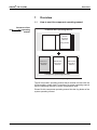
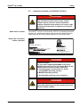
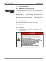
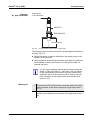
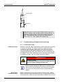
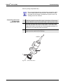
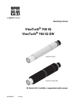
OPERATING MANUAL ba76040e04 ViSolid 700 IQ ViSolid 700 IQ H ViSolid 700 IQ SW ViSolid® 700 IQ ® ViSolid 700 IQ SW ® ViSolid 700 IQ H IQ SENSORNET TOTAL SUSPENDED SOLIDS SENSOR 05/2014 ViSolid® 700 IQ (SW) For the most recent version of the manual, please visit www.ysi.com. Contact Copyright YSI 1725 Brannum Lane Yellow Springs, OH 45387 USA Tel: +1 937-767-7241 800-765-4974 Email: [email protected] Internet: www.ysi.com © 2014 Xylem Inc. ba76040e04 05/2014 ViSolid® 700 IQ (SW) Contents ViSolid® 700 IQ (SW) - Contents 1 Overview . . . . . . . . . . . . . . . . . . . . . . . . . . . . . 1-1 1.1 1.2 1.3 1.4 2 How to use this component operating manual . . . . 1-1 Structure of the ViSolid® 700 IQ (SW) total suspended solids sensor 1-2 Recommended fields of application . . . . . . . . . . . . 1-2 Features of the ViSolid® 700 IQ (SW) . . . . . . . . . . 1-3 Safety . . . . . . . . . . . . . . . . . . . . . . . . . . . . . . . 2-1 2.1 Safety information . . . . . . . . . . . . . . . . . . . . . . . . . 2-1 2.1.1 Hazard warnings in this operating manual . 2-1 2.1.2 Safety information on the product . . . . . . . 2-1 2.2 Safe operation . . . . . . . . . . . . . . . . . . . . . . . . . . . . 2-2 2.2.1 Authorized use . . . . . . . . . . . . . . . . . . . . . . 2-2 2.2.2 Requirements for safe operation . . . . . . . . 2-2 2.2.3 Unauthorized use . . . . . . . . . . . . . . . . . . . . 2-2 2.3 Hazardous location use (ViSolid® 700 IQ H) . . . . . 2-3 3 Commissioning . . . . . . . . . . . . . . . . . . . . . . . 3-1 3.1 IQ SENSORNET system requirements . . . . . . . . . . . 3-1 3.2 Scope of delivery . . . . . . . . . . . . . . . . . . . . . . . . . . 3-1 3.3 Installation . . . . . . . . . . . . . . . . . . . . . . . . . . . . . . . 3-1 3.3.1 Safety guidelines for installation in a hazardous location (H-models only) . . . . . . . . . . . . . . . . . . . . . 3-1 3.3.2 General information . . . . . . . . . . . . . . . . . . 3-2 3.3.3 Flow direction . . . . . . . . . . . . . . . . . . . . . . . 3-3 3.3.4 Sensor angle . . . . . . . . . . . . . . . . . . . . . . . 3-3 3.3.5 Sensor orientation . . . . . . . . . . . . . . . . . . . 3-4 3.3.6 Distances from the ground and wall . . . . . . 3-5 3.4 Installation examples . . . . . . . . . . . . . . . . . . . . . . . 3-6 3.4.1 Measurement in an open pool or channel . 3-6 3.4.2 Measurement in pipelines . . . . . . . . . . . . . 3-8 3.5 Commissioning / Readiness for measuring . . . . . 3-10 3.5.1 Connect the sensor . . . . . . . . . . . . . . . . . 3-10 3.5.2 Selecting the Measuring mode . . . . . . . . . 3-12 3.5.3 Setting tableViSolid® 700 IQ (SW) . . . . . . 3-13 4 Measuring . . . . . . . . . . . . . . . . . . . . . . . . . . . . 4-1 4.1 Measuring operation . . . . . . . . . . . . . . . . . . . . . . . 4-1 4.2 Calibration for TSS measurement . . . . . . . . . . . . . 4-2 4.2.1 General information . . . . . . . . . . . . . . . . . . 4-2 ba76040e04 05/2014 0-1 ViSolid® 700 IQ (SW) Contents 4.2.2 4.2.3 4.2.4 5 Default calibration . . . . . . . . . . . . . . . . . . . . 4-3 Correction factor . . . . . . . . . . . . . . . . . . . . . 4-5 User calibration . . . . . . . . . . . . . . . . . . . . . . 4-7 Maintenance, cleaning, accessories . . . . . . .5-1 5.1 General information . . . . . . . . . . . . . . . . . . . . . . . . 5-1 5.2 Cleaning the sensor shaft and measurement windows 5-1 5.3 Accessories . . . . . . . . . . . . . . . . . . . . . . . . . . . . . . 5-3 6 What to do if ... . . . . . . . . . . . . . . . . . . . . . . . . .6-1 7 Technical data . . . . . . . . . . . . . . . . . . . . . . . . .7-1 7.1 7.2 7.3 7.4 Measuring characteristics . . . . . . . . . . . . . . . . . . . . 7-1 Application characteristics . . . . . . . . . . . . . . . . . . . 7-2 General data . . . . . . . . . . . . . . . . . . . . . . . . . . . . . . 7-3 Instrument safety . . . . . . . . . . . . . . . . . . . . . . . . . . 7-4 7.4.1 General instrument safety . . . . . . . . . . . . . 7-4 7.4.2 Hazardous location ratings (H models) . . . 7-4 7.5 Electrical data . . . . . . . . . . . . . . . . . . . . . . . . . . . . . 7-5 8 Indexes . . . . . . . . . . . . . . . . . . . . . . . . . . . . . . .8-1 8.1 Explanation of the messages . . . . . . . . . . . . . . . . . 8-1 8.1.1 Error messages . . . . . . . . . . . . . . . . . . . . . 8-1 8.1.2 Info messages . . . . . . . . . . . . . . . . . . . . . . 8-2 8.2 Status info . . . . . . . . . . . . . . . . . . . . . . . . . . . . . . . 8-3 9 Contact Information . . . . . . . . . . . . . . . . . . . . .9-1 9.1 Ordering & Technical Support . . . . . . . . . . . . . . . . 9-1 9.2 Service Information . . . . . . . . . . . . . . . . . . . . . . . . 9-1 10 Appendix . . . . . . . . . . . . . . . . . . . . . . . . . . . .10-1 10.1 Check calibration values . . . . . . . . . . . . . . . . . . . 10-1 0-2 ba76040e04 05/2014 ViSolid® 700 IQ (SW) Overview 1 Overview 1.1 How to use this component operating manual Structure of the IQ SENSORNET operating manual IQ Sensor Net Operating Manual System Operating Manual (Ring Binder) IQ Sensor Operating Manual MIQ Module Operating Manual MIQ Terminal Operating Manual Component Operating Manuals Fig. 1-1 Structure of the IQ SENSORNET operating manual The IQ SENSORNET operating manual has a modular structure like the IQ SENSORNET system itself. It consists of a system operating manual and the operating manuals of all the components used. Please file this component operating manual into the ring binder of the system operating manual. ba76040e04 05/2014 1-1 ViSolid® 700 IQ (SW) Overview 1.2 Structure of the ViSolid® 700 IQ (SW) total suspended solids sensor 1 2 3 Fig. 1-2 1 Shaft 2 Connection head 3 Optical measurement window made of sapphire 1.3 ViSolid® 700 IQ ViSolid® 700 IQ SW ® Structure of the total suspended solids sensor (example: ViSolid 700 IQ) Recommended fields of application Stationary measurement of the total suspended solids in slurries and in water/wastewater applications. Stationary measurements in seawater and brackish water, aquaculture. The ViSolid® 700 IQ (SW) is particularly well suited for applications in polluted measuring media, e.g. in wastewater treatment plants, thanks to its robust construction and its efficient ultrasound cleaning system. It provides very high measurement accuracy with low maintenance costs. ViSolid® 700 IQ H 1-2 Stationary measurements in water/wastewater applications in Class I Division 2 hazardous locations. ba76040e04 05/2014 ViSolid® 700 IQ (SW) Overview 1.4 Features of the ViSolid® 700 IQ (SW) Total suspended solids measurement The measurement of the total suspended solids in aqueous media with the ViSolid® 700 IQ (SW) is carried out as a scattered light measurement. This records the suspended proportion of total suspended solids (TSS). Ultrasound cleaning system The ultrasound cleaning system ensures low maintenance and longterm reliable measurement operation. The ultrasound source integrated in the sensor excites the front face containing the measurement windows to oscillations in the ultrasound range. The resulting movement of the surface prevents the growth of pollution right from the start and, thus, ensures reliable measured values during continuous operation. AutoRange function Within the enormously large measuring range (0 - 40000 mg/l SiO2 and 0 - 40000 mg/l TSS depending on the measured material), the AutoRange function selects the optimum resolution for the respective measured value. SensCheck function This monitoring function that is integrated in the sensor is used to continually check the sensor function and to register any malfunctions caused by the measuring medium. The correct operation of the ultrasound cleaning system is also continuously monitored. ba76040e04 05/2014 1-3 Overview 1-4 ViSolid® 700 IQ (SW) ba76040e04 05/2014 ViSolid® 700 IQ (SW) Safety 2 Safety 2.1 Safety information 2.1.1 Hazard warnings in this operating manual The hazard warnings are defined for the following levels of danger: DANGER DANGER indicates an imminently hazardous situation which, if not avoided, will result in death or serious injury. WARNING WARNING indicates a potentially hazardous situation which, if not avoided, could result in death or serious injury. CAUTION CAUTION indicates a potentially hazardous situation which, if not avoided, may result in minor or moderate injury. NOTICE NOTICE is used to address practices not related to personal injury. 2.1.2 Safety information on the product Note all labels, information signs and safety symbols on the product. ba76040e04 05/2014 2-1 ViSolid® 700 IQ (SW) Safety 2.2 Safe operation 2.2.1 Authorized use The authorized use of the ViSolid® 700 IQ (SW) consists of its use as a total suspended solids sensor in the IQ SENSORNET. Please observe the technical specifications according to chapter 7 TECHNICAL DATA. Only operation according to the instructions given in this operating manual is considered to be authorized. Any other use is considered to be unauthorized. Unauthorized use invalidates any claims with regard to the guarantee. NOTICE The sensor warms up during operation in the air. Consequently, pollution can collect in the vicinity of the measurement window due to the evaporation of liquid. Therefore, avoid any lengthy operation in the air. 2.2.2 Requirements for safe operation Note the following points for safe operation: The product may only be operated according to the authorized use specified above. The product may only be supplied with power by the energy sources specified in this operating manual. The product may only be operated under the environmental conditions specified in this operating manual. The product or its components may only be opened if this is required for installation and maintenance work and described in the operating manual. 2.2.3 Unauthorized use The product must not be put into operation if: it is visibly damaged (e.g. after being transported) it was stored under adverse conditions for a lengthy period of time (storing conditions, see chapter 7 TECHNICAL DATA) 2-2 ba76040e04 05/2014 ViSolid® 700 IQ (SW) Safety 2.3 Hazardous location use (ViSolid® 700 IQ H) DANGER Explosion hazard. Only hazardous location rated sensor models ("Hazloc Sensor") must be used in hazardous locations. Read the name plate on the sensor shaft and verify that the sensor is rated for your specific application. Rated sensor models The ViSolid® 700 IQ H (YSI-Order No. 207012Y) is rated for hazardous location use. Hazardous location rated sensors are identified by the name plate with the rating details engraved on the sensor shaft: Name plate of a Hazloc sensor (example) ViSolid 700 IQ H ###### ###### ###### 28124 ######### ############### #################### ################# DANGER Explosion hazard. The associated apparatus MIQ/BB2 (YSI part no. 207002Y) has to be used for connection. Refer to the following documents for proper installation: Control drawing, YSI document no. 28124 (see MIQ/BB2 operating manual) MIQ/BB2 operating manual All applicable electrical code regulations. DANGER Explosion hazard. This product does not meet the requirements of the directive 94/9/EC (ATEX). ba76040e04 05/2014 2-3 Safety 2-4 ViSolid® 700 IQ (SW) ba76040e04 05/2014 ViSolid® 700 IQ (SW) Software statuses of the controller and terminal components Commissioning 3 Commissioning 3.1 IQ SENSORNET system requirements The operation of the ViSolid® 700 IQ (SW) requires the following software versions in the IQ SENSORNET: MIQ/MC2 Controller software: Version 3.42 or higher MIQ/TC 2020 XT Terminal software: DIQ/S 182 Controller software: Version 3.47 or higher ViSolid® 700 IQ (SW) Sensor software: 3.2 Version 3.42 or higher Version 2.50 or higher Scope of delivery Total suspended solids sensor, ViSolid® 700 IQ (SW) Operating manual 3.3 Installation 3.3.1 Safety guidelines for installation in a hazardous location (H-models only) DANGER Explosion hazard. Only hazardous location rated sensor models ("Hazloc Sensor") must be used in hazardous locations. Verify the rating on the product name plate on the sensor shaft. The associated apparatus MIQ/BB2 (YSI part no. 207002Y) has to be used for connection. Refer to the following documents for proper installation: Control drawing, YSI document no. 28124 (see MIQ/BB2 operating manual) MIQ/BB2 operating manual All applicable electrical code regulations. ba76040e04 05/2014 3-1 ViSolid® 700 IQ (SW) Commissioning 3.3.2 General information The measuring principle of the ViSolid® 700 IQ (SW) (scattered light measurement) places specific requirements on the measurement location and on the installation of the sensor. If there is a low level of total suspended solids (< 2000 mg/l SiO2 or < 1000 mg/l TSS), infrared light penetrates deep into the sample. Thus, the measuring environment can have a significant effect on the measured value displayed. Light that is reflected or scattered by the ground or wall can strike the detector in the sensor and, thus, simulate an increased level of total suspended solids. Scattered light can be kept away from the measurement windows to a great extent by favorable positioning of the sensor. Therefore, an optimum installation position is particularly important for the measurement of lower values of total suspended solids. Always maintain a distance of at least 10 cm from the ground and wall. The following factors affect the measurement of the TSS contents: Inclination of the sensor (see section 3.3.4) Sensor orientation around its longitudinal axis (see section 3.3.5) Distances from the ground and wall (see section 3.3.6) Light-colored, heavily light-scattering surfaces in the measuring vessel (e.g. vessel inner surfaces) or in the measuring environment. Unfavorable geometry of the measuring vessel or unfavorable positioning of the sensor in the measuring vessel. Spatial proximity of two optical sensors. Very bright ambient light at the measuring location, e.g. direct sunlight in the open channel 3-2 ba76040e04 05/2014 ViSolid® 700 IQ (SW) Commissioning 3.3.3 Flow direction Generally, in flowing media, the measurement window should be clearly pitched towards the flow (angle of incidence approx. 20 to 45 °). Exception: If there is a high proportion of foreign bodies with fibrous or flat profiles such as, e.g. hair, twines or foliage, it can be advantageous to tilt the sensor in the direction of flow so that the measurement window is turned away from the flow. 3.3.4 Sensor angle Marking Side view: 10 cm 0° Fig. 3-1 20 ° 45 ° Effect of the sensor angle on scattering and reflection from the ground and wall Scattering and reflection are lowest at a sensor angle of 45° and at a minimum distance of 10 cm to the ground and walls (see section 3.3.6). ba76040e04 05/2014 3-3 ViSolid® 700 IQ (SW) Commissioning 3.3.5 Sensor orientation The sensor has a marking (arrow symbol on the shaft or glue dot on connection head). The infrared beam emerges from the front of the sensor at a small angle in the direction opposite the marking. Marking in this direction Infrared beam ViSolid 700 IQ SW Fig. 3-2 Direction of the infrared beam relative to the marking The angle of incidence to the ground and walls can be affected by rotating the sensor around its longitudinal axis. The sensor should be turned so that as little light as possible that is scattered or reflected by the wall or ground strikes the measurement window again. 3-4 ba76040e04 05/2014 ViSolid® 700 IQ (SW) Commissioning 3.3.6 Distances from the ground and wall If there is a low level of total suspended solids (< 2000 mg/ l SiO2 or < 1000 mg/l TSS), the effects of the measurement environment can simulate a higher content of total suspended solids. The effect of the measurement environment can be reduced by ensuring the optimum conditions (see section 3.3.2). The following graphic indicates the minimum distances of the measurement windows to the ground or wall, which must be observed. The effect of the distances on the measured value has been determined for various wall materials (aluminum, black plastic) in the case of a sensor placed vertically to the wall in drinking water or water with 1000 mg/l SiO2. Aluminium (in water with 1000 mg/l SiO2) Pretended additional amount of total suspended solids [1000 mg/l SiO2] Black plastic material 2.0 0,9 1.6 0,7 1.2 0,5 0.8 0,3 0.4 0,1 0 Aluminium (in drinking water each) x 0 4 8 12 16 20 24 28 32 36 40 Distance x [cm] Fig. 3-3 Effect of ground and wall distances on the measurement of TSS At low levels of total suspended solids, a minimum distance of at least 10 cm must be kept from the ground or wall. If an optimum installation is not possible due to the structural conditions at the measuring location (e.g. in narrow pipelines), the effects of the measurement environment can be compensated by user calibration (see section 4.2.4). ba76040e04 05/2014 3-5 ViSolid® 700 IQ (SW) Commissioning 3.4 Installation examples As a rule, the ViSolid® 700 IQ (SW) will measure interference-free when the distances and angles etc. specified are observed. However, interferences at the measuring location (see section 3.3.2) may require special adaptations of the installation. 3.4.1 Measurement in a pool Measurement in an open pool or channel The total suspended solids sensor can be suspended in the pool on a chain (e.g. with EH/F 170 swing mounting assembly and EH/U 170 sensor holder). Make sure the sensor cannot bump against any walls or obstacles. Alternatively, the sensor can be immersed in the sample using a pendulum mounting assembly, e.g. EH/P 170 pendulum mounting assembly, (please note the minimum immersion depth). 3-6 ba76040e04 05/2014 ViSolid® 700 IQ (SW) Measurement in a channel Commissioning In an open channel, the sensor can be immersed in the sample using a wall mounting assembly, e.g. EH/W 170 wall mounting assembly, (please note the minimum immersion depth). Mount the sensor rigidly in the channel. At the same time, tilt the sensor approx. 45 ° against the direction of the flow. Marking in this direction 45 ° n io ct ire D of w flo Immersion depth min. 7 cm min. 10 cm min. 10 cm Gro min. 10 cm und Fig. 3-4 Total suspended solids sensor in an open channel with wall mounting assembly, EH/W 170 For exceptions to the direction of flow, see section 3.3.3 FLOW DIRECTION. ba76040e04 05/2014 3-7 ViSolid® 700 IQ (SW) Commissioning 3.4.2 Measurement in pipelines If there is a low level of total suspended solids (< 2000 mg/ l SiO2 or < 1000 mg/l TSS), the effects of the measurement environment can simulate a higher content of total suspended solids. The effect of the measurement environment can be reduced by ensuring the optimum conditions (see section 3.3.2). If an optimum installation is not possible due to the structural conditions at the measuring location (e.g. in narrow pipelines), the effects of the measurement environment can be compensated by user calibration (see section 4.2.4). If deposits occur on the pipe walls, the calibration should be repeated at regular intervals. Example: 45 ° pipe installation The pipe should be straight for a length of approx. 25 cm beyond the installation location. Angled or tapered pipes can cause interference effects in the case of low levels of total suspended solids. ADA-DF 9 Swivel nut Marking aid in this direction EBST 700-DU/N Direction of flow Infrared beam ca. 25 cm straight pipe Fig. 3-5 Total suspended solids sensor in the pipe with EBST 700-DU/N flow-thru adapter Fig. 3-5 shows the installation of the EBST 700-DU/N flow-thru adapter for installation in a pipeline (DN 50). The infrared beam points in the opposite direction to the direction of flow. The marking on the sensor points towards the pipeline (see Fig. 3-5). For exceptions to the direction of flow, see section 3.3.3 FLOW DIRECTION. 3-8 ba76040e04 05/2014 ViSolid® 700 IQ (SW) Example: 90 ° pipe installation Commissioning Marking aid in this direction ADA-DF 9 EBS 700-DU/N Infrared beam Fig. 3-6 Total suspended solids sensor in a pipe (90 °) The following points must be observed for a right-angled installation in the pipe (Fig. 3-6): Rotate the sensor so that the marking on the sensor points in the direction of the pipe axis Select a position where the pipe diameter is as large as possible as the installation location (see section 3.3.6 DISTANCES FROM THE GROUND AND WALL). In a 90° pipe installation with low levels of total suspended solids (< 2000 mg/l SiO2 or < 1000 mg/l TSS), the effects of the measurement environment can have a particularly significant effect on the measured value. Ensure the optimum conditions of the measurement environment (see section 3.3.2). Marking aid ba76040e04 05/2014 1 Connect the SACIQ (SW) sensor connection cable to the plug head connector of the sensor and screw it tight (see section 3.5.1). 2 Attach a marking aid (adhesive strips or similar) in the same position as the marking on the sensor to the plug head connector. 3-9 ViSolid® 700 IQ (SW) Commissioning Marking aid Marking Fig. 3-7 3 Connection cable Marking aid Install the sensor in the flow-thru adapter with the aid of the ADA-DF 9 adapter (see operating manual of the adapter). To ensure the correct position, loosen the coupling ring on the EBST 700-DU/N somewhat and align the marking aid as shown in Fig. 3-5. Then, tighten the coupling ring. 3.5 Commissioning / Readiness for measuring 3.5.1 Connect the sensor A sensor connection cable of the SACIQ or SACIQ SW type is required to connect the sensor. The cable is available in different lengths. Compared to the standard model SACIQ, the SACIQ SW sensor connection cable is optimized regarding its corrosion resistance in seawater and brackish water and adapted for use in conjunction with the ViSolid® 700 IQ SW. Information on this and other IQ SENSORNET accessories is given in the YSI catalog and on the Internet. DANGER Explosion hazard. For hazardous location use only the cable types listed in the control drawing must be used. How to connect the SACIQ (SW) sensor connection cable to the terminal strip of a MIQ module is described in chapter 3 INSTALLATION of the IQ SENSORNET system operating manual. Are the plug connections dry? 3 - 10 Before connecting the sensor and sensor connection cable, please make sure that the plug connections are dry. If moisture gets into the plug connections, first dry the plug connections (dab them dry or blow ba76040e04 05/2014 ViSolid® 700 IQ (SW) Commissioning them dry using compressed air). Do not suspend the sensor on the sensor connection cable. Use a sensor holder or an armature. Information on this and other IQ SENSORNET accessories is given in the YSI catalog and on the Internet. Connecting the sensor to the sensor connection cable 4 Take the protective caps off the plug connections of the sensor and the SACIQ sensor connection cable, and keep them safe. 5 Plug the socket of the SACIQ (SW) sensor connection cable onto the plug head connector of the sensor. At the same time, rotate the socket so that the pin in the plug head connector (1) clicks into one of the two holes in the jack. 6 Then screw the coupling ring (2) of the sensor connection cable onto the sensor up to the stop. SACIQ 2 1 Fig. 3-8 ba76040e04 05/2014 Connect the sensor 3 - 11 ViSolid® 700 IQ (SW) Commissioning 3.5.2 Selecting the Measuring mode Specify the following data in the Measuring mode setting Matrix type (1 or 2) Display (TSS or SiO2) Unit (mg/l or %) Determining the matrix type Measurement in mg/l TSS (total suspended solids) Measurement in mg/l SiO2 (silicon dioxide) Determine the matrix type for your application with the aid of the following table: Measuring medium: Matrix type 1 Outflow of preclarification X Activated slurry X Return slurry X Matrix type 2 Primary slurry X Sediment slurry X Concentrated slurry X Measuring medium: SiO2 content: 0 ... 25000 mg/l Matrix type 1 Matrix type 2 X X SiO2 content: 15000 ... 300000 mg/l If the matrix type for a measuring medium cannot be determined using this table, select matrix type 1 and then carry out a user calibration (see section 4.2.4). If the graph of the value pairs corresponds to one of the forms 1 to 3 (see section 4.2.4), matrix type 1 is suitable. If the graph of the value pairs corresponds to form 4, matrix type 2 must be selected. Factory settings 3 - 12 Measuring mode: Mtrx.type1:mg/l TSS Measuring range: AutoRange ba76040e04 05/2014 ViSolid® 700 IQ (SW) Commissioning 3.5.3 Setting tableViSolid® 700 IQ (SW) Setting Selection/values Explanation Measuring mode (see section 3.5.2) Mtrx.type1:mg/l TSS – Content of total suspended solids in mg/l Matrix type1:% TSS – Content of total suspended solids in % Mtrx.type2:mg/l TSS – Content of total suspended solids in mg/l Matrix type2:% TSS – Content of total suspended solids in % Mtrx.type1:mg/l SiO2 – Content of SiO2 in mg/l Matrix type1:% SiO2 – Content of SiO2 in % Mtrx.type2:mg/l SiO2 – Content of SiO2 in mg/l Matrix type2:% SiO2 – Content of SiO2 in % Signal averaging 1 ... 600 secs Response time of the signal filter. Depending on the sample matrix, the measured values may oscillate more or less (e.g. due to foreign bodies or air bubbles). The signal filter reduces the limits of variation of the measured value. The signal filter is characterized by the signal averaging time. This is the time after which 90 % of a signal change is displayed. Ultrasonic cleaning On / On Off / On Pulse / On On / Off Off / Off Pulse / Off Switches on or off the ultrasound cleaning and SenseCheck functions (Pulse = pulse operation). Save and quit The system confirms the saving of the settings and the display switches to the next higher level. Quit The display switches to the next higher level without saving the new settings. TSS measuring mode: Calibration data TSS measuring mode: Correction factor ba76040e04 05/2014 Default calibration The factory calibration data for TSS are used (see section 4.2.2). User calibration User entered calibration data are used (see section 4.2.4). 0.50 ... 2.00 The Correction factor setting enables a simple calibration (see section 4.2.3). 3 - 13 ViSolid® 700 IQ (SW) Commissioning Setting Selection/values Explanation TSS measuring mode: Menu selection: User calibration Basic settings Selection between the use of the basic settings and the entry of calibration value pairs. Value pairs 1..3 Value pairs 4..6 Value pairs 7..8 For the selection of the value pairs, fields open for the entry of the values TSS value 1 to TSS value 8. and the individual values SiO2 value 1 to SiO2 value 8. Starting with TSS value 1, determine and enter the content of total suspended solids in mg/l TSS, and, in the case of SiO2 value 1, enter the related measured SiO2 value. The input precision is 1 mg/l in each case. Note: The values must be entered in descending order. If this sequence is not kept to, a calibration error is displayed after leaving the menu. All the entered values become invalid. TSS measuring mode: Measuring ranges 0 ... 400.0 mg/l 0 ... 4000 mg/l 0 ... 25000 mg/l 0 ... 400.0 ppm The setting AutoRange = automatic changeover of the measuring range can be selected in all measuring modes. Measuring range for the measuring mode Mtrx.type1:mg/l TSS 0 ... 4000 ppm Measuring ranges for the Matrix type1:% TSS measuring mode 0 ... 2.500 % 0 ... 4000 mg/l 0 ... 40000 mg/l 0 ... 4000 ppm 0 ... 4.000 % Measuring ranges for the Mtrx.type2:mg/l TSS measuring mode Measuring ranges for the Matrix type2:% TSS measuring mode 0 ... 40.00 % 0 ... 100.0 % 3 - 14 ba76040e04 05/2014 ViSolid® 700 IQ (SW) Commissioning Setting Selection/values Explanation Measuring mode SiO2: Measuring ranges 0 ... 400.0 mg/l Measuring ranges for the Mtrx.type1:mg/l SiO2 measuring mode 0 ... 4000 mg/l 0 ... 25000 mg/l 0 ... 400.0 ppm The setting AutoRange = automatic changeover of the measuring range can be selected in all measuring modes. 0 ... 4000 ppm Measuring ranges for the Matrix type1:% SiO2 measuring mode 0 ... 2.500 % 0 ... 4000 mg/l 0 ... 40000 mg/l 0 ... 4000 ppm 0 ... 4.000 % Measuring ranges for the Mtrx.type2:mg/l SiO2 measuring mode Measuring ranges for the Matrix type2:% SiO2 measuring mode 0 ... 30.00 % Carrying out settings ba76040e04 05/2014 Switch to the main settings menu from the measured value display with <S>. Then navigate to the setting menu (setting table) of the sensor. The exact procedure is described in the relevant IQ SENSORNET system operating manual. 3 - 15 Commissioning 3 - 16 ViSolid® 700 IQ (SW) ba76040e04 05/2014 ViSolid® 700 IQ (SW) Measuring 4 Measuring The ViSolid® 700 IQ (SW) measures the light scattered and reflected by the total suspended solids in the measuring medium. The level of total suspended solids that corresponds to the amount of light measured is displayed. As different suspended solids scatter and reflect light in different ways, the display of a suspended solid contents in mg/l must be referred to a standard. A factory calibration to SiO2 is stored in the sensor. 4.1 Measuring operation 1 Immerse the sensor in the measuring medium. 2 Read the measured value on the terminal of the IQ SENSOR NET system. Large temperature differences between the sensor and measuring medium can falsify the measurement result. Thus, as a precaution during commissioning, wait for 15 minutes before using the measured value. The allowed temperature of the measuring medium is 0 ... 60 °C. The ultrasound cleaning system automatically switches off if the temperature of the measuring medium increases to more than 60 °C. When the temperature drops below 60 °C, it switches itself on again. Switching off at temperatures above 60 °C prevents any overheating, for example if the minimum immersion depth of the sensor is not maintained. ba76040e04 05/2014 4-1 ViSolid® 700 IQ (SW) Measuring Why calibrate? 4.2 Calibration for TSS measurement 4.2.1 General information The following factors can change with time and affect the measurement results: the optical characteristics, e.g. color and particle size, and the density of the measuring medium (e.g. dependent on the season) the conditions at the measuring location (e.g. due to growing deposits on the ground and walls) The effect of the measurement environment can be reduced by ensuring the optimum conditions (see section 3.3.2) and can be compensated by a user calibration (see section 4.2.4). When to calibrate? A new calibration is required if there is any change of the characteristics of the measuring medium or any change of the environment at the measuring location. Calibration data that are entered are stored in the controller and, thus, assigned to the measuring location (and not the sensor). Thus, if the sensor is replaced, no new calibration is required. How is a calibration carried out? The actual level of total suspended solids of your measuring medium is determined by a reference measurement (e.g. gravimetric according to DIN 38414). If the reference measurements do not deviate from the optically determined level of total dissolved solids of the ViSolid® 700 IQ (SW), the sensor is already optimally adapted to the measuring situation. If the reference measurements deviate from the optically determined level of total dissolved solids of the ViSolid® 700 IQ (SW), a calibration is required. The following calibration options are available: Calibration by adapting the Correction factor setting if the values displayed with Default calibration deviate from the actual values by a specific factor Performance of a User calibration if the values displayed with Default calibration and Correction factor no longer agree with the actual values 4-2 ba76040e04 05/2014 ViSolid® 700 IQ (SW) Measuring 4.2.2 Default calibration Default calibration for matrix type 1 The factory calibration curve for matrix type 1 was determined by measurements of typical activated and return slurries and can be used for similar applications after adaptation of the Correction factor setting (see section 4.2.3). Below the smallest value, the calibration curves are extended to the zero point and, above the largest value, they are extended to the end of the measuring range. Value pairs 1 7.16 TS [1000 mg/l] SiO2 value [1000 mg/l] SiO2 25 0,9 20 0,7 15 0,5 10 0,3 5 0,1 0 Fig. 4-1 05/2014 3 4 5 6 7 8 9 10 17.57 15.55 11.62 8.80 6.21 4.42 3.39 2.40 0.77 0.25 Total suspended solids [1000 mg/l] TSS ba76040e04 2 0 7.05 1 6.52 5.85 4.86 3.91 3.22 2.60 1.37 0.61 2 3 4 6 7 5 SiO2 [1000 mg/l ] 8 9 10 Default calibration for matrix type 1 4-3 ViSolid® 700 IQ (SW) Measuring Default calibration for matrix type 2 The factory calibration curve for matrix type 2 was determined by measurements of typical decaying slurries and can be used for similar applications after adaptation of the Correction factor setting (see section 4.2.3). Value pairs 1 2 3 4 5 6 7 8 9 10 100 59.40 32.00 20.70 14.90 9.97 5.26 2.37 1.48 0.41 SiO2 value [1000 mg/l] SiO2 7.62 TSS [1000 mg/l] Total suspended solids [1000 mg/l] TSS 100 0,9 90 0,7 80 0,5 70 0,3 60 0,1 50 0,9 40 0,7 35 0,5 20 0,3 10 0,1 0 Fig. 4-2 Influences 7.16 0 1 6.26 2 5.60 3 5.00 4.28 3.19 1.73 1.13 0.32 4 6 7 5 SiO2 [1000 mg/l ] 8 9 10 Default calibration for matrix type 2 If there is a low level of total suspended solids (< 2000 mg/l SiO2 or < 1000 mg/l TSS), the effects of the measurement environment can simulate a higher content of total suspended solids. The effect of the measurement environment is minimized by exactly observing the installation position (see section 3.3.2). If an optimum installation is not possible due to the structural conditions at the measuring location (e. g. in narrow pipelines), interference effects can be compensated by a User calibration (see section 4.2.4). 4-4 ba76040e04 05/2014 ViSolid® 700 IQ (SW) Measuring 4.2.3 Correction factor The setting of the Correction factor provides a simple option for adapting the calibration to the current conditions. With the Correction factor setting you correct the measured value and have it indicated on the display. A change of the Correction factor setting is practical if the measured values of the ViSolid® 700 IQ (SW) are generally too high or too low in comparison to reference measurements by a specific factor. Correction factor 1.00 Correction factor 0.50 TSS [1000 mg/l] 0,9 0,7 0,5 0,3 0,1 SiO2 [1000 mg/l ] Fig. 4-3 Effect of the Correction factor on the displayed measured value The Correction factor is calculated using the following formula: FN = FA * SR/SV ba76040e04 05/2014 Variable Explanations FN Correction factor, to be recalculated FA Correction factor, currently set in the Calibration data menu SR TSS value, newly determined from reference measurement SV TSS value, newly determined from measurement with ViSolid® 700 IQ (SW) 4-5 ViSolid® 700 IQ (SW) Measuring Determining the Correction factor 1 Bring the sensor into the measuring position. 2 In the setting table of the TSS sensor, note down the currently set Correction factor as the value for FA. 3 Switch to the measured value display with <M>. 4 When the measured value is stable, read the TSS value, convert it into the unit (mg/l) if necessary, and note it down as the value for Sv. 5 Take a sample as close to the same time as the TSS measurement as possible and as close to the sensor as possible. 6 Determine the level of total suspended solids of the sample according to a reference procedure (e. g. gravimetric according DIN 38414), convert it into the unit (mg/l) if necessary, and note it down as the value for SR. 7 Calculate the Correction factor. FN = FA * SR/SV Setting the Correction factor 8 Set the new Correction factor in the Calibration data menu (see section 3.5.3). The Correction factor setting affects each TSS measuring mode and all calibration data. Also, if there is a change of the measuring mode or calibration data, the Correction factor is retained. Therefore, after every change of the settings in the Calibration data menu, check the Correction factor. 4-6 ba76040e04 05/2014 ViSolid® 700 IQ (SW) Measuring 4.2.4 User calibration The displayed values of total suspended solids are calculated with the aid of the stored calibration data. In the mg/l TSS measuring mode, the value mg/l SiO2 marked with "#" is displayed as the secondary measured value. Effect of the measurement environment on the graph of the value pairs TSS (laboratory) - SiO2 (ViSolid® 700 IQ (SW)) Graphs of the value pairs Explanations SiO2 [mg/l] The determination of the calibration value pairs is carried out by reference measurements according to an independent procedure. At the point of time of the calibration, the measuring medium should be in a state representative of the later measurement (type and amount of total suspended solids, coloration, etc.). The results from the calibration are manually entered in the setting table of the ViSolid® 700 IQ (SW). Form 1: The graph has a gradient > 0 at every point. A calibration is possible for the whole range. SiO2 [mg/l ] TSS [mg/l] SiO2 [mg/l ] TSS [mg/l] TSS [mg/l] SiO2 [mg/l] A TSS [mg/l] B ba76040e04 05/2014 Form 2: The graph has a gradient > 0 at every point. At very low levels of TSS, the effect of the measurement environment leads to slightly increased values of SiO2. A calibration is possible for the whole range. Form 3: The graph has a gradient < 0 in the range of smaller levels of TSS. The effect of the measurement environment leads to greatly increased values of SiO2 in the range of smaller TSS below the point (A). A calibration is only possible in the range TSS > A. Form 4: The graph has a gradient < 0 in the range of greater levels of total suspended solids. A calibration for matrix type 1 is only possible in the range of TSS < B. For measurements in the range of TSS > B, select matrix type 2. 4-7 ViSolid® 700 IQ (SW) Measuring A measurement of the total suspended solids will deliver ever more accurate measurement results the closer the composition of the measuring medium corresponds to the status at the time of the calibration. If there is a fundamental change of the characteristics of the sample, a new calibration may be necessary. Procedure of the calibration 1 Bring the sensor into the measuring position. 2 In the setting table of the TSS sensor, select the mg/l TSS measuring mode and the AutoRange measuring range (see section 3.5.3). 3 Switch to the measured value display with <M>. 4 When the measured value is stable, read the SiO2 value (marked with "#"), convert it into the unit (mg/l) if necessary, and note it down. 5 Take a sample as close to the same time as the SiO2 measurement as possible and as close to the sensor as possible. 6 Determine the level of total suspended solids of the sample according to a reference procedure (e.g. gravimetric according to DIN 38414) and note it down together with the measured value of SiO2 as the TSS/SiO2 value pair in mg/l. At least one value pair and a maximum of eight value pairs can be entered for a valid calibration. Keeping to the descending order of values is very important. Not keeping to the order will result in a calibration error. 7 For a multi-point calibration: Repeat the determination of the value pair for various concentrations of the sample. Samples of different concentrations of total suspended solids can be obtained from the sample taken by: diluting it with water depositing the total suspended solids and decanting off the remaining water Before measuring the samples, make sure that the total suspended solids are actually in suspension. 8 4-8 Sort the value pairs in descending order and, if necessary, enter them in a table and diagram (see chapter 10). ba76040e04 05/2014 ViSolid® 700 IQ (SW) Measuring Below the smallest value, the calibration curve is extended to the zero point and, above the largest value, it is extended to the end of the measuring range. 9 Check the form of the calibration curve. If the calibration curve corresponds to form 3, change the conditions at the measuring location and determine the calibration values again or do not carry out any measurements in the range below the turning point (A). 10 In measuring mode with matrix type 1: If individual calibration values lie outside the measuring range, change the conditions at the measuring location and determine the calibration values again or select measuring mode for matrix type 2 The entry of calibration values that exceed the measuring range leads to a calibration error. The size of the measuring range is dependent on the selected measuring mode (matrix type) (see section 3.5.3). Entering the Calibration data 11 Switch to the setting table of the TSS sensor. 12 Change to the Calibration data menu with <> and <OK>. 13 Select the User calibration menu item with <> and <OK>. 14 Select the Menu selection menu item with <> and <OK>. 15 Select the Value pairs 1..3 menu item with <> and <OK>. For examples of valid value pair data, see section 4.2.2. A maximum of 8 value pairs can be entered for the User calibration. 16 ba76040e04 05/2014 Select the TSS value 1 menu item with <> and <OK>. 4-9 ViSolid® 700 IQ (SW) Measuring 17 Enter the value for the contents of total suspended solids (TSS in mg/l) from the reference measurement with <> and <OK>. 18 Select the SiO2 value 1 menu item with <> and <OK>. 19 Enter the associated SiO2 value (SiO2 in mg/l) measured with the ViSolid® 700 IQ (SW) with <> and <OK>. 20 Repeat steps 13 - 18 until the required number of value pairs (between 1 and 8) has been entered. 21 Terminate the entry of the calibration data with Save and quit. To simplify the settings when entering the calibration data, standardized high resolutions of 1 mg/l are possible. However, it is not sensible to use these in all cases. The calibration data entered are evaluated by the system. The entry of the calibration value pairs can have the following results: Results after entry of Calibration data Possible displays Log book entries (meaning/actions) Measured value display Successful new valid calibration value pairs were entered for the sensor. "----" Calibration value pairs not accepted. Sensor blocked for measurement. – Enter the values again making sure that they are entered in descending order – Viewing the log book entry. Information on the contents and structure of the log book and how you can call it up is given in the LOG BOOK chapter of the IQ SENSORNET system operating manual. 4 - 10 ba76040e04 05/2014 ViSolid® 700 IQ (SW) Maintenance, cleaning, accessories 5 Maintenance, cleaning, accessories 5.1 General information WARNING Chemical or biological hazard. Contact with the sample can be harmful to the user. Depending on the type of sample, suitable protective measures must be taken (protective clothing, goggles, etc.). The ViSolid® 700 IQ (SW) sensor does not usually require any maintenance. The continuously running ultrasound system prevents the accumulation of pollution right from the start. If the sensor remains in the sample for any length of time when the system is not operating, we recommend to clean the shaft and measurement windows. 5.2 Cleaning the sensor shaft and measurement windows During normal operation (e.g. municipal wastewater), cleaning is recommended: if there is any pollution (according to visual check) if the sensor was not in operation for a lengthy period of time but was immersed in the measuring medium if the measured values are suspected of being incorrect (usually too low) if the SensCheck message appears in the log book (when using samples of matrix type 1) for regular cleaning (when using samples of matrix type 2) if there is any suspicion that the measurement window is polluted, e.g. by dried on dirt during operation in the open air Cleaning agents ba76040e04 05/2014 Contamination Cleaning agents Sludge and loosely adhering dirt or biological films Soft cloth or soft brush, warm tap water with detergent Salt and / or lime deposits Acetic acid (volume percentage = 20 %), soft cloth or soft sponge 5-1 ViSolid® 700 IQ (SW) Maintenance, cleaning, accessories CAUTION Acetic acid irritates the eyes and the skin. When handling acetic acid, always wear protective gloves and protective goggles. We do not recommend unscrewing the sensor from the sensor connection cable when cleaning the sensor shaft and measurement window. Otherwise, moisture and/or dirt can get into the plug connection where it can cause contact problems. If you need to disconnect the sensor from the sensor connection cable, please note the following points: Before disconnecting the sensor from the SACIQ (SW) sensor connection cable, remove any larger pieces of contamination from the sensor, particularly in the area of the plug connection (brush it off in a bucket of tap water, wash it off with a hose or wipe it off with a cloth). Unscrew the sensor from the SACIQ (SW) sensor connection cable. Always place a protective cap on the plug head of the sensor and on the SACIQ (SW) sensor connection cable so that no moisture or dirt can get into the contacting surfaces. It is included in the standard scope of delivery of the SACIQ SW sensor connection cable. In corrosive environments, close the socket of the sensor connection cable with the screwable SACIQ-Plug when it is dry in order to protect the electrical contacts from corrosion. The protective plug is available as an accessory (see section 5.3 ACCESSORIES). NOTICE The sensor warms up during operation in the air. Consequently, pollution can collect in the vicinity of the measurement window due to the evaporation of liquid. Therefore, avoid any lengthy operation in the air. Cleaning 5-2 1 Pull the sensor out of the sample. 2 Remove any coarse pollution from the sensor (by brushing it off in a bucket of tapwater, spraying it off with a hose or wiping with a cloth). 3 Clean the sensor shaft and the measurement window as described in the section CLEANING AGENTS. 4 Then, rinse it thoroughly with tap water. ba76040e04 05/2014 ViSolid® 700 IQ (SW) Maintenance, cleaning, accessories 5.3 Accessories Description Model Order no. Screwable plug for sensor connection cable SACIQ-Plug 480 065Y Information on other IQ SENSOR NET accessories is given in the YSI catalog and on the Internet. ba76040e04 05/2014 5-3 Maintenance, cleaning, accessories 5-4 ViSolid® 700 IQ (SW) ba76040e04 05/2014 ViSolid® 700 IQ (SW) What to do if ... 6 What to do if ... Mechanical damage to the sensor Cause Display always shows "0" Cause Remedy – First calibration value pair incomplete – Enter the TSS value for the first calibration value pair TSS display does not correspond to the TSS value according to the laboratory determination Cause Remedy – Correction factor incorrectly set – Set up the correction factor again: Correction factor = TSS value (laboratory) / TSS value (display) Display of OFL Cause Remedy – Measuring range exceeded – See log book – First calibration value pair incomplete – Enter the SiO2 value for the first calibration value pair – Two identical SiO2 values entered one after the other – Enter the value pairs in descending order Cause Remedy – Measured value invalid – See log book – Incorrect calibration value entered – Correct the calibration values and enter them again Display of main parameter TSS: "----" Secondary parameter SiO2: "OFL" Cause Remedy – The optical measuring range for SiO2 is exceeded. The display of a valid TSS measured value is not possible. – See log book (message code EA6243, see section 8.1.1) Measured value fluctuating heavily Cause Remedy – There are bubbles of gas in the medium in front of the measurement windows – Check the installation position of the sensor (see section 3.3 and section 3.4) Display of "----" ba76040e04 05/2014 Remedy – Return the sensor 6-1 ViSolid® 700 IQ (SW) What to do if ... Cause Remedy – Signal averaging time too short for low values of total suspended solids – Increase signal averaging time – Inhomogeneous measuring medium Measured values too low Cause Remedy – Measurement window dirty – Clean the measurement window (see section 5.2) Measured values too high Cause Remedy – There are bubbles of gas in the medium in front of the measurement windows – Check the installation position of the sensor (see section 3.3 and section 3.4) – Light scattering on the walls – Check the installation position of the sensor (see section 3.3 and section 3.4) – If necessary, compensate for any effects that cannot be cleared by calibration – Measurement window dirty 6-2 – Clean the measurement window (see section 5.2) ba76040e04 05/2014 ViSolid® 700 IQ (SW) Measuring principle Technical data 7 Technical data 7.1 Measuring characteristics Procedure for measuring scattered light. Measurement in following units: mg/l TSS (total suspended solids) % TSS (total suspended solids) mg/l SiO2 % SiO2 Measuring ranges and resolutions ba76040e04 05/2014 Measured parameter Measuring ranges Resolution mg/l TSS 0 ... 400.0 mg/l 0 ... 4000 mg/l 0 ... 25000 mg/l 0 ... 40000 mg/l 0.1 mg/l 1 mg/l 1 mg/l 1 mg/l % TSS 0 ... 400.0 ppm 0 ... 4000 ppm 0 ... 2.500 % 0 ... 4.000 % 0 ... 40.00 % 0 ... 100.0 % 0.1 ppm 1 ppm 0.001 % 0.001 % 0.01% 0.1% mg/l SiO2 0 ... 400.0 mg/l 0 ... 4000 mg/l 0 ... 25000 mg/l 0 ... 40000 mg/l 0.1 mg/l 1 mg/l 1 mg/l 1 mg/l % SiO2 0 ... 400.0 ppm 0 ... 4000 ppm 0 ... 2.500 % 0 ... 4.000 % 0 ... 30.00 % 0.1 ppm 1 ppm 0.001 % 0.001 % 0.01 % 7-1 ViSolid® 700 IQ (SW) Technical data 7.2 Allowed temperature range Allowed pH range of the measuring medium Pressure resistance Application characteristics Measuring medium 0 °C ... + 60 °C (32 ... 140 °F) Storage/transport - 5 °C ... + 65 °C (23 ... 149 °F) 4 ... 12 Sensor with connected SACIQ (SW) sensor connection cable: Max. allowed overpressure 106 Pa (10 bar) Max. allowed underpressure temporarily 5 x 10⁴ Pa (0,5 bar) The sensor fulfills all requirements according to article 3(3) of the directive 97/23/EC ("pressure equipment directive"). Type of protection Sensor with connected SACIQ (SW) sensor connection cable: IP 68, 10 bar (106 Pa) Depth of immersion Operating position Fields of application 7-2 min. 10 cm; max. 100 m depth see section 3.3 INSTALLATION Water and wastewater monitoring ba76040e04 05/2014 ViSolid® 700 IQ (SW) Technical data 7.3 Dimensions (in mm) General data ViSolid 700 IQ (H): 365 40.0 Socket SACIQ... ViSolid 700 IQ SW: 365 32 40.0 Weight (without sensor connection cable) Connection technique Material 204 Socket SACIQ... 59.5 ViSolid® 700 IQ (H) approx. 990 g approx. 1420 g VisoTurb® 700 IQ SW Connection using SACIQ (SW) sensor connection cable Shaft: – ViSolid® 700 IQ (H) – ViSolid® 700 IQ SW Sensor head: – ViSolid® 700 IQ (H) – ViSolid® 700 IQ SW V4A stainless steel 1.4571 * POM V4A stainless steel 1.4571 * Titanium Measurement window Sapphire Plug head connector housing POM Plug, 3-pole ETFE (blue) Tefzel® * Stainless steel can be susceptible to corrosion at chloride concentrations of ≥ 500 mg/l and more. We recommend to use SW sensors for applications in such test solutions. Material ba76040e04 05/2014 Shaft V4A stainless steel 1.4571 * 7-3 ViSolid® 700 IQ (SW) Technical data Measurement window Sapphire Plug head connector housing POM Plug, 3-pole ETFE (blue) Tefzel® * Stainless steel can be susceptible to corrosion at chloride concentrations of ≥ 500 mg/l and more. Cleaning system Automatic sensor monitoring (SensCheck function) Ultrasound principle Identification of any measurement fault (in matrix type 1) Identification of any failure of the cleaning system 7.4 Instrument safety 7.4.1 General instrument safety Applicable norms – UL 61010-1 – CAN/CSA C22.2 # 61010.1 7.4.2 Applicable directives and standards Hazardous location ratings (H models) In addition to the standards listed in chapter 7.4.1, the ViSolid® 700 IQ H conforms to the following directives and standards: ANSI/ISA-12.12.01 CAN/CSA C22.2 # 213 The ViSolid® 700 IQ H is a non-incendive electrical equipment for use in Class I Division 2 hazardous locations. Hazardous location rating 7-4 ViSolid® 700 IQ H Class I Division 2 Group D T6 Class I Zone 2 Group IIA T6 Associated apparatus MIQ/BB2, YSI part no. 207002Y Control Drawing YSI document no. 28124 ba76040e04 05/2014 ViSolid® 700 IQ (SW) Technical data 7.5 ba76040e04 05/2014 Electrical data Rated voltage (non-H models) 24 V DC via the IQ SENSORNET (for more details, see chapter TECHNICAL DATA of the IQ SENSORNET system operating manual) Voltage range (ViSolid® 700 IQ H) 14 V DC ... 24 V DC via the MIQ/BB2 barrier box (=associated apparatus) Power consumption 1.5 W Protective class III 7-5 Technical data 7-6 ViSolid® 700 IQ (SW) ba76040e04 05/2014 ViSolid® 700 IQ (SW) Indexes 8 Indexes 8.1 Explanation of the messages This chapter contains a list of all the message codes and related message texts that can occur in the log book of the IQ SENSORNET system for the ViSolid® 700 IQ (SW) sensor. Information on the contents and structure of the log book and the structure of the message code is given in the LOG BOOK chapter of the IQ SENSORNET system operating manual. All message codes of the ViSolid® 700 IQ (SW) end with the number "342". 8.1.1 Error messages Message code Message text EA2342 Sensor temperature too high! * Check process and application EA3342 Sensor temperature too low! * Check process and application EA6342 Meas. range exceeded or undercut * Check process * Select other meas. range * Submerse sensor in sample * Select bubble-free spot for measurement * Remove any foreign matter from sensor * Avoid influence of large foreign matter * Clean sensor * Increase signal average time EA7342 Ultrasound cleaning system switched off * Check sample temperature * Submerse sensor in sample ba76040e04 05/2014 8-1 ViSolid® 700 IQ (SW) Indexes Message code Message text EC2342 User calibration error, check TSS/SiO2 pairs of variates * All TSS values within measuring range? (see operating manual) * At least one value pair entered? * All TSS and SiO2 values entered? * All TSS/SiO2 pairs in descending order? * Pair 1 = highest TSS and SiO2 value? EI1342 Operational voltage too low * Check installation and cable lengths, Follow installation instructions * Power unit(s) overloaded, add power unit(s) * Defective components, replace components EI2342 Operational voltage too low, no operation possible * Check installation and cable lengths, Follow installation instructions * Power unit(s) overloaded, add power unit(s) * Check terminal and module connections * Defective components, replace components ES1342 Component hardware defective * Contact service ESD342 SensCheck: Measurement interfered * Submerse sensor in sample * Select bubble-free spot for measurement * Remove any foreign matter from sensor * Avoid influence of large foreign matter * Clean sensor * Increase signal average time ESE342 SensCheck: Ultrasound cleaning system has failed * Return sensor for repair 8.1.2 Info messages Message code Message text IA1342 Ultrasound cleaning system switched on * Check sensor visually * Clean sensor if necessary 8-2 ba76040e04 05/2014 ViSolid® 700 IQ (SW) Indexes 8.2 Status info The status info is a piece of coded information about the current state of a sensor. Each sensor sends this status info to the controller. The status info of sensors consists of 32 bits, each of which can have the value 0 or 1. Status info, general structure 0 1 2 3 4 5 6 7 8 9 10 11 12 13 14 15 1 0 0 0 0 0 0 0 0 0 0 0 0 0 0 0 (general) 0 0 0 0 0 0 0 0 0 0 0 0 0 0 0 0 (internal) 16 17 18 19 20 21 22 23 24 25 26 27 28 29 30 31 The bits 0 - 15 are reserved for general information. The bits 16 - 21 are reserved for internal service information. You obtain the status info: via a manual query in the menu, Einstellungen/Setup/Service/List of all components (see system operating manual) via an automated query – of a superordinate process control (e. g. when connected to the Profibus) – of the IQ Data Server (see operating manual of the IQ SENSORNET software pack) The evaluation of the status info, e.g. in the case of an automated query, has to be made individually for each bit. ViSolid® 700 IQ (SW) Status info ba76040e04 05/2014 Status bit Explanation Bit 0 Component hardware defective Bit 1 SensCheck: Measurement interfered Bit 2 SensCheck: Ultrasound cleaning system has failed Bit 3-31 - 8-3 Indexes 8-4 ViSolid® 700 IQ (SW) ba76040e04 05/2014 ViSolid® 700 IQ (SW) Contact Information 9 Contact Information 9.1 Ordering & Technical Support Telephone: (800) 897-4151 (937) 767-7241 Monday through Friday, 8:00 AM to 5:00 PM ET Fax: (937) 767-1058 Email: [email protected] Mail: YSI Incorporated 1725 Brannum Lane Yellow Springs, OH 45387 USA Internet: www.ysi.com When placing an order please have the following information available: YSI account number (if available) Model number or brief description Quantity 9.2 Name and Phone Number Billing and shipping address Purchase Order or Credit Card Service Information YSI has authorized service centers throughout the United States and Internationally. For the nearest service center information, please visit www.ysi.com and click ‘Support’ or contact YSI Technical Support directly at 800-897-4151. When returning a product for service, include the Product Return form with cleaning certification. The form must be completely filled out for an YSI Service Center to accept the instrument for service. The Product Return form may be downloaded at www.ysi.com and clicking on the ‘Support‘ tab. ba76040e04 05/2014 9-1 Contact Information 9-2 ViSolid® 700 IQ (SW) ba76040e04 05/2014 ViSolid® 700 IQ (SW) Appendix 10 Appendix 10.1 Check calibration values By checking the value pairs, possible calibration errors can already be avoided before the entry of the calibration value pairs. Carry out a check using the EC2342 message text: * All TSS values within measuring range? (see operating manual) * At least one value pair entered? * All TSS and SiO2 values entered? * All TSS/SiO2 pairs in descending order? * Pair 1 = highest TSS and SiO2 value? Sequence Max. value Value pairs 1 -> 2 3 Min. values 4 5 6 7 8 Total suspended solids [mg/l] TSS TS [1000 mg/l] SiO2 value [mg/l] SiO2 10 0,9 8 0,7 6 0,5 4 0,3 2 0,1 0 0 2 4 6 8 10 12 14 16 18 20 SiO2 [1000 mg/l] For examples of valid value pair data, see section 4.2.2. The graph of the value pairs must not contain any turning point in the required measuring range (see section 4.2.4). ba76040e04 05/2014 10 - 1 Appendix 10 - 2 ViSolid® 700 IQ (SW) ba76040e04 05/2014 Xylem |'zīləm| 1) The tissue in plants that brings water upward from the roots; 2) a leading global water technology company. We're 12,500 people unified in a common purpose: creating innovative solutions to meet our world's water needs. Developing new technologies that will improve the way water is used, conserved, and re-used in the future is central to our work. We move, treat, analyze, and return water to the environment, and we help people use water efficiently, in their homes, buildings, factories and farms. In more than 150 countries, we have strong, long-standing relationships with customers who know us for our powerful combination of leading product brands and applications expertise, backed by a legacy of innovation. For more information on how Xylem can help you, go to www.xyleminc.com YSI 1725 Brannum Lane Yellow Springs, OH 45387 Tel: +1 937-767-7241; 800-765-4974 Fax: +1 937-767-1058 Email: [email protected] Web: www.ysi.com ©Xylem Inc