1
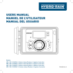
USER'S MANUAL PROGRAM RAIN DELAY RESET RUN TIME BUDGET F O F H OW TE N AUTO OF ST T I A RT M E SET DATE CL SE OC T K Models: HRC 100-C (96054) 4-Station Update all titles to Indoor/Outdoor Mount, Irrigation Controller HRC 100-C (96057) 6-Station Update all titles to Indoor/Outdoor Mount, Irrigation Controller HRC 100-C (96058) 9-Station Update all titles to Indoor/Outdoor Mount, Irrigation Controller HRC 100-C (96059) 12-Station Update all titles to Indoor/Outdoor Mount, Irrigation Controller PN 96054-24 rB 2 Congratulations on selecting your new Hydro-Rain irrigation controller! With Hydro-Rain’s exclusive Easy-Set Logic™, simple programming and setup are combined with the latest controller technology and versatility. Your HRC 100 C provides convenience and flexibility, letting you run a fully automatic, a semi-automatic, or a manual watering program for all your watering needs. Although this controller is so easy to program that you likely will not need instructions, we recommend that you read this manual fully before installation so that you understand all of the advanced features. Table of Contents Section 1: Get to know your HRC 100 C . . . . . . . . . . . . 4 Section 2: Installation . . . . . . . . . . . . . . . . . . . . . . . . . . . 5 Section 3: Programming with Easy-Set Logic™ . . . . . . 9 Section 4: Additional Features . . . . . . . . . . . . . . . . . . . 11 Section 5: Reference . . . . . . . . . . . . . . . . . . . . . . . . . . . 13 3 Section 1: Get to know your HRC 100 C A Lock and latch B Weather Resistant Cover C Dial D Digital Display E Battery Compartment F Swing Door panel A B PROGRAM E D RAIN DELAY RESET F F BUDGET O F H OW TE N OF RUN TIME 4 C ST T I A RT M E AUTO SET DATE CL SE OC T K Buttons Function ENTER MANUAL To confirm a new setting To water manually CLEAR To clear a setting PROGRAM To move to different programs: A, B, and C ARROW [ ] To skip to the next setting / watering station or move to other programs/settings ARROW [ ] To go back to the previous setting / watering station or move to other programs/settings RAIN DELAY To pause operation for 24-72 hours due to rain or other factors [+] To increase a numeric setting [–] To decrease a numeric setting and to select “Manual TEST ALL” programming (see instructions) Dial Position Function RUN Set Program is operating automatically SET CLOCK Set current time SET DATE Year, Month, and Day START TIME Set time to begin watering RUN TIME Set watering duration for each station HOW OFTEN Set frequency of watering days BUDGET Adjust overall watering as a percentage OFF Turn all stations/functions off Section 2: Installation Required Tools • Phillips Screwdriver • Wire Strippers Installation Steps 1. Select a Location 2. Mount the Controller 3. Connect Valve Wires to Controller 4. Connect Electrical Power 5. Activate Battery 5 1. Select a Location When choosing a location for your HRC 100 C, consider the following: • Choose location near a power source (if hard wiring) or electrical outlet when using the supplied power cord. • Ensure operating temperatures are not below 0° Celsius or above 70° Celsius. • Place it away from direct sunlight if possible. • Ensure at least 23 cm of space to the left of the sprinkler controller box for the door to swing open after installation. 2. Mount the Controller • Use the mounting template (included) to mark the mounting screw location on the wall. See Figure 1 • Install a No. 8 screw (included) into wall in the upper template location. Leave the screw head protruding 3 mm from wall. Use expanding anchors (included) in plaster or masonry, if necessary, for a secure hold. •S lip the HRC 100 C over protruding screw (using keyhole slot in back). See Figure 2 •D rive a No. 8 screw through one of the two pre-formed holes located in lower back cabinet. See Figure 2 • Locate the controller where there is easy access to sprinkler wire (from valves). If mounted in an outdoor location, shut the compartment door to keep the controller safe from weather damage. To lock: insert the key and turn clockwise to the locked position. MOUNTING TEMPLATE 106 mm proof no: 3 dimensions: flat: w: 9" Printers are responsible for meeting print production requirements. Any changes must be approved by the client and Fluid Studio. printed piece must meet designated specifications on this form. h: 7" Figure 1: Use Mounting Template (included) date: 10.05.07 des: SM spck: SM job no: 07WTM005259 finished: w 9" d: 0" h 7" colors Registration crop color non printing color non printing K PMS ???? PMS ???? client: Orbit sku: 57880 p 801 295 9820 f 801 951 5815 www.fluid-studio.net 1065 South 500 West Bountiful, Utah 84010 upc: ? ????? ????? ? file name: 07WTM005259 57880-04 rA.indd software: Illustrator CS2 additional instructions: · · PMS ???? © 2007 Fluid Studio. This work is the property of Fluid Studio, and cannot be used, reproduced or distributed in any way without their express permission. Keyhole Note: Sprinkler controllers are weather-resistant to UL-50 and ETL® Listings, but should not be placed in areas where continuous water could cause damage. 3 mm No. 8 Screw Pre-formed mounting holes 6 Wall Figure 2: Hang timer on screw using keyhole 3. Connect Valve Wires to Controller to the controller. To avoid electrical hazards, only one valve should be connected to each station. See Figure 4 • Strip 12 mm of the plastic insulation off the end of each valve wire at the controller. • Connect one wire from each valve (it doesn’t matter which wire) to a single “Common” sprinkler wire (usually white). • Connect the remaining wire from each valve to a separate colored sprinkler wire. See Figure 3 Important: The wire can be buried in the ground; however, for more protection wires can be pulled through PVC pipe and buried underground. Be careful to avoid burying the wires in locations where they could be damaged by digging or trenching in the future. Your controller is equipped with the simple “push-in” terminals for easy connection. Connect common wire to the common terminal. Connect remaining wires to corresponding terminal locations. Note: The maximum loading for each station/pump is 250mA, the maximum loading for the controller is 500mA. If the distance between the sprinkler controller and valves is under 210 m, use sprinkler wire or .5mm (20 gauge AWG) plastic jacketed thermostat wire to connect the sprinkler controller to the valves. If the distance is over 210 m, use 1.5mm (16 gauge AWG) wire. Only connect one valve to each terminal (station). Station 1 Common Wire Strip wire To Timer Wire Nut Push in Solenoid Valve Figure 3: Wiring Electric Valves Push tab upward to release wire Important: All wires should be joined together using good quality waterproof cable connectors. Wiring Electric Valves Each valve has two wires. One wire (it doesn’t matter which one) is to be connected as the common. The other valve wire is to be connected to the specific station wire that will control that valve. The common wires for all the valves can be connected together to one common wire going Figure 4 7 • Turn off the AC power at the AC circuit breaker and apply an appropriate safety lockout. Verify that the power has been turned off to the installation site using an AC voltmeter set for the correct measurement range. • Use power feed wire of 2.5 mm (14 gauge AWG) minimum with a temperature rating of 68° Celsius or higher. • Install the conduit and associated fittings. Connect the AC electrical power wiring to the source by following all the right codes and local standards. The wire can be buried in the ground; however, for more protection wires should be pulled through electrical conduit and buried underground. Be careful to avoid burying the wires in locations where they could be damaged by digging or trenching in the future. Caution: Do not connect the sprinkler controller to one phase of a three phase power system used by a pump or other electrical equipment. PROGRAM RAIN DELAY RESET OF F RUN • Take the cord (running from the controller to the junction box) from the junction box and cut it to length. Remove the outer insulation (from cord) to expose the three wires. • Connect the source wires to the wires extending from the sprinkler controller. • For USA: Take care to follow the correct color code. Connect the Green for Ground, Black for Live, and White for Neutral. Often the source ground may be bare copper conductor rather than green wire. • Make sure all connections are made with code-approved insulated connectors. ST T I A RT M E CL SE OC T K SET DATE • Connect the junction box to the controller using a 12 mm nipple (Junction box and nipple not included). [See Figure 5] Connect the source power conduit to the entrance of the junction box, following all the appropriate codes. BUDGET utdoor Locations—If a covered Ground Fault Interrupter (GFI) O outlet is available, insert the power cord into the 240V outlet. If no outlet is available, the controller must have the wiring permanently installed (*see Figure 5) This sprinkler controller has two holes at the bottom for wire access. Use a 12 mm Nipple to connect the sprinkler controller to a standard electrical junction box. Both connector and junction box must be UL Listed or equivalent or comply with IEC or EN standards or equivalent. O F H OW TE N Indoor Locations—Insert the power cord into an 240V electrical outlet. requirements of the National Electrical Code and other state and local codes. RUN TIME 4. Connect Electrical Power TEST CYCLE 13 mm Connector Junction Box 3 Wire Connectors • Be sure to place a weatherproof gasket and lid on the junction box. • Turn AC power on at the AC circuit breaker. Important: Installation Using Permanent Wiring The sprinkler controller has a built-in transformer that must be connected to an AC line voltage source. Check the back of the sprinkler controller box for power requirements. Local building and electrical codes usually require that an approved electrical conduit and electrical fittings be used to connect exterior wall-mounted equipment to AC power. Please check local codes. Any permanent connection should be made by a licensed electrical contractor in accordance with the 8 Figure 5: Using a Junction Box Note: For outdoor applications it is recommended that a qualified electrician complete the installation in accordance with electrical codes and regulations. When used outdoors this sprinkler controller is intended for use with a Ground Fault Interrupter (GFI) protected circuit. 5. Activate Battery One Lithium CR2032 battery (included) is required to retain the program in memory during power loss. Annual replacement is recommended. Remove the plastic strip to activate the pre-installed battery. (See page 12 for battery replacement) Tip: To increase or decrease more rapidly, hold down either the [+] or [-] buttons until the display goes into rapid advance mode. • Press the [ ] buttons to set a.m./p.m. • Turn dial to accept time 2. Set Date • Turn dial to [SET DATE] • Y/M/D will appear (blinking letter indicates selection) PROGRAM RAIN DELAY Remove plastic strip to activate battery ET ST TI AR M T E SET DATE RUN TIME C SE LO T C K AUTO FF O O HO FT W EN BUDGET Note: The battery alone will not operate the valves in your sprinkler system. The sprinkler controller has a built-in transformer that must be connected to an AC voltage source. Section 3: Programming with Easy-Set Logic™ • Press the [+/–] buttons to set the correct year, then press [ENTER] or [ ] • Press the [+/–] buttons to set the correct month, then press [ENTER] • Press the [+/–] buttons to set the correct date • Turn dial to accept date 3. Start time • Turn dial to [START TIME] • Press the [+/–] buttons to select time you’d like your watering to begin (Time will adjust in 15 minute increments) The display will show A note about multiple programs The HRC 100 C provides the flexibility of using 3 independent programs (A, B, C). A program is where you store all of your sprinkler settings. It consists of a group of stations set to specific start times and run times. Multiple programs allow you to run different valves on different days with different run times. While many applications only require one program (A), using multiple programs can be useful for drip areas, newly planted lawn, or rotary sprinkler stations. Using programs to group stations with similar water needs will maximize irrigation efficiency. Primary programming can be accomplished in just a few steps. Primary Programming Press the [RESET] to clear any previous factory programming Please note that [START TIME] is the time of day that your programmed watering starts. You can set up to 4 start times. All stations that have a programmed run time (how long) will run in sequence at these times Note: Start-Time Stacking When a start time is set before the previous program has completed, that start time will be “stacked” or delayed, and will start upon completion of the previous program. 1. Set Clock • Turn dial to [SET CLOCK] • Press the [+/–] buttons to set the current time of day 9 Example: Bill just planted new grass seed and wants to water three times per day. He sets START TIME 1 for 5 a.m., START TIME 2 for 12 p.m., and START TIME 3 for 5 p.m. He also sets HOW OFTEN to INT (interval) EVERY 1 DAYS (see section 3, HOW OFTEN). In AUTO mode the system will water 3 times per day. Once Bill’s sod is established he can CLEAR start times 2 and 3 and return to watering just once per day. 4. Run Time • Turn the dial to [RUN TIME] Days of the Week • Your dial should be set to [HOW OFTEN] - Display will show the current program (A, B, C) - Press the [ ] buttons to move from one day to another - Press [+] or [ENTER] to select a day for watering. A frame will appear around the selected days. •T o delete a previously entered day, press [-] or [CLEAR] Example: Monday, Wednesday, & Friday Intervals • Use the [ ] buttons to move to the INTERVAL option “INT” •P ress [+/–] buttons to select the number of days between watering Example: An interval of 1 will water every day; an interval of 3 will water every 3rd day, etc. STATION is the area that will be watered by each valve. On this screen the RUN TIME or duration for each station is set. • Press the [ ] to select a station and press the [+/–] buttons to enter the watering duration for that station • Press [ENTER] or the [ ] buttons to move to the next station/valve, and enter watering duration for each station 5. How Often • Turn the dial to [HOW OFTEN] - this screen allows you to set how often to water. Odd or Even Days • Use the [ ] buttons to move to the ODD or EVEN day watering - Press [+] or [ENTER] • Selecting a different option or pressing clear will erase the previous selection Example: Odd: 1st, 3rd, 5th, etc. Example: Even: 2nd, 4th, 6th, etc. There are 3 options provided: Turn the dial to [AUTO] and that’s it! You have programmed your controller! 1. Days of the week (Mon, Tues, Wed, etc.) Turn dial to [AUTO] to activate your program 2. Intervals (Every “X” number of days) 3. Odd or Even Days Note: If your program is lost, the factory installed fail-safe program will turn on each station every day for 10 minutes Note: Your prior programming will not be disturbed unless altered. Always be aware of the program you are in (A, B, C) when you are making changes. Reviewing and Changing Your Program If you want to review or change the start times, run times, or how often to water, simply follow the directions again for that option. After reviewing or changing a watering schedule, remember to turn the dial back to [AUTO] for automatic operation. 10 Section 4: Additional Features • To adjust press [+/–] buttons, press [ENTER] Rain Delay • If using multiple programs (A, B, C) Press the [PROGRAM] button to move to the desired program and make the needed adjustment [RAIN DELAY] allows you to delay your sprinkler controller from watering for a set period of time. Delay settings are 24, 48, and 72 hours. • Turn dial to [RUN] Example: Bill’s watering duration is set at 60 minutes however; it is the spring time so he wants to water half as long so he sets his budgeting to 50%, his controller will now water for 30 minutes. Manual Watering Your HRC 100 C has the ability to allow you to manually water without disturbing the preset program. • Press the [RAIN DELAY] button to automatically delay watering for 24 hours • Turn the dial to [AUTO] • If a longer Rain Delay is desired, press the [ ] buttons to increase or decrease the setting. • Press [ENTER] or wait 10 seconds and the selected rain delay will begin. • [CLEAR] button stops the rain delay and scheduled watering will resume. • At the end of the selected rain delay amount of time, automatic watering resumes. • While in rain delay mode, the controller display will switch between the actual time and the remaining hours of the delay, every 2 seconds Water Budgeting Water Budgeting is a simple way to adjust your watering duration to match seasonal watering needs. Water Budgeting works by increasing or decreasing watering duration for all stations in each program. Press the [PROGRAM] button to select the program you wish to budget. Adjustment range is from 10% to 200% by increments of 10%. The default value is 100%. The budgeting will remain on the adjusted range until you change it. To set budgeting: • Turn dial to [BUDGET] • Press the [MANUAL] button. Display will show ABC and ALL. After a few seconds or by pressing [ENTER] the controller will begin manual watering • All stations will water consecutively for their programmed duration Note: If the run times have not been set, the controller will not initiate manual watering and the screen will return to the current time. • To specify a specific program or stations, Press the [ ] buttons to select A, B, C. • Press [ENTER] to activate •T o select a specific station, continue pressing the [ ] buttons until desired station number appears • Press the [+/–] to enter the desired duration from 1 to 240 minutes • Wait 5 seconds and your station will begin • To stop Manual Watering press [CLEAR] • The controller will go back to your original automatic watering schedule 11 Example: To manually water on station 3 for five minutes, press the [MANUAL] button then press the [ ] buttons until you see station 3; using the [+/–] buttons, set duration to five minutes; press [ENTER]. Rain Sensor Bypass This HRC 100 C is equipped with a sensor override “on/ off” switch. This switch is for use during maintenance and repairs, so the sprinkler controller can be operated even if the rain sensor is in active mode. Note: After the [MANUAL] button has been pushed, if a selection is not made within 5 seconds all stations and programs will begin watering using the programmed RUN TIMES. If no RUN TIMES have been set, nothing will happen and the display will return to the time of day. Important: If the rain sensor switch is in the “on” position and no sensor is connected, the sprinkler controller will not operate. To resume the HRC 100 C operation place the switch TIMER in the off position 1 2 24VAC SENSOR COMMON PUMP OUT Manual “Test” Cycle The HRC 100 C is capable of running a “Manual Test Cycle” which will run all stations for as little time as 1 minute or as much as 240 minutes. This feature is very useful upon completion of system installation or service. To access this function, follow these instructions. • Turn the Dial to “Run”. • Press the “Manual/Enter” portion of the key pad and then press the “-” key located just above the words “TEST CYCLE” on the front lower right hand side of the controller (show an image). Note- if you do not press the “-” button prior to 5 seconds the manual test start up process will have to be repeated to activate the function. Figure 6: Connecting Wired (not RF wireless) Rain Sensor • When the function is done correctly the lcd screen will indicate ”MANUAL”, “STATION A” (for all stations), and the default cycle duration of each station (2 minutes). To increase or decrease test cycle station duration time, use the “+” button or to decrease use the “-” button. Pump Start & Master Valve This sprinkler controller allows a master valve or pump start relay to operate whenever a station is on. Note: If you are activating a pump from this controller, you must purchase a Pump Start Relay. From the pump start relay (or master valve); connect one wire to the “Pump” terminal and the other wire to the “Common” terminal. • Upon arrival at desired test cycle time, press “ENTER”. To abort test, press “CLEAR”. When the test cycle is complete the HRC 100 C will automatically return to your pre-set station durations and begin watering upon next scheduled watering cycle. Replacing the Battery Controller requires a CR2032 Lithium battery Connecting a Rain Sensor • The battery will maintain your program in case of an AC power loss • Connect the rain sensor wires to the wiring terminal ports (yellow in color) labeled “Sensor” Note: Refer to your rain sensor manual for specific wiring instructions. PROGRAM • Place the sensor on/off switch to the “on” position to begin operation (see Figure 6) To Remove RAIN DELAY RESET RUN TIME FF BUDGET O O HO FT W EN AUTO 12 ST TI AR M T E SET DATE C SE LO T C K Figure 7: Battery Compartment • Battery should last approximately one year • Open by sliding the battery tray out to the right • Insert one CR2032 battery into the compartment with the + side up • Slide back into place. A weak or missing battery can cause the time, date, and program to be erased after a power failure. If this happens, you will need to install a fully charged battery and reprogram the controller. Tip: Replace battery every year, to avoid loss of programming Note: A battery alone will not operate the valves in your sprinkling system. The sprinkler controller has a built-in transformer that must be connected to an AC line voltage source. Section 5: Reference TERM DEFINITION START TIME The time the program begins watering the first programmed station. VALVE Supplies water to a specific station or area. The opening and closing of the valve is accomplished through electrical current supplied by the sprinkler controller. MASTER VALVE Typically located at the main water source. Turns on and off water for the entire irrigation system when not in use. MULTIPLE START TIMES A controller feature that allows a program to be operated multiple times on the same watering day. OVERLAPPING PROGRAMS When a “Start Time” is set for a program before the previous program has completed. PROGRAM (A, B, C) Individual programs as set by the user. Each program operates independently. If one program overlaps the other the programs will be “stacked.” After the first program finishes the next program will begin. RAIN DELAY A feature that postpones the running of a scheduled watering program for a specific duration. SOLENOID The electrical part on an irrigation valve that opens and closes the valve. SPRINKLER CONTROLLER A device which instructs the station valves to operate. STATION A grouping of sprinklers operated by a single valve which is controlled by the controller. WATERING BUDGETING Adjusts your overall watering program as a percentage of total watering duration. 13 Troubleshooting PROBLEM POSSIBLE CAUSE 1. Faulty solenoid connection One or more valves do not turn on 2. Wire damaged or severed 3. Flow control stem screwed down, shutting valve off 4. Programming is incorrect 1. Water pressure is too high Stations turn on when they are not supposed to 2. More than one start time is programmed 3. AM/PM is incorrect 1. Faulty valve One station is stuck on and will not shut off 2. Particles of dirt or debris stuck in valve 3. Valve diaphragm faulty 1. Transformer defective or not connected All valves do not turn on 2. Programming is incorrect 14 Controller will not power up 1. Transformer not plugged into a working outlet Valves continue to turn on and off when they are not programmed 1. More than one start time is programmed with overlapping schedules 2. Excessive pressure HELP www.hydrorain.com Before returning this controller to your authorized Hydro-rain distributor, contact Hydro-Rain® Technical Service at: 1-888-493-7672 LISTINGS The HRC 100 C is tested to UL-50 standard & is ETL® listed. Appropriate international models are CSA® and CE® approved and comply with EN60730-2-7: 1991+A1 and AS/NZS 3100: 2002 standards This Class B digital apparatus complies with Canadian ICES-003. Disconnection : Type 1Y Normal Pollution Situation. The supply cord of this control can be replaced only by the manufacturer or his accredited service agent. TRADEMARK NOTICE The information in this manual is primarily intended for the user who will establish a watering schedule and enter that schedule into the sprinkler controller. This product is intended to be used as an automatic sprinkler irrigation controller for activating 24 VAC irrigation valves, as described in this manual. Warning: Changes or modifications to this unit not expressly approved by the party responsible for compliance could void the user’s authority to operate the equipment. NOTE: This equipment has been tested and found to comply with the limits for a Class B digital device, pursuant to Part 15 of the FCC Rules. These limits are designed to provide reasonable protection against harmful interference in a residential installation. This equipment generates, uses and can radiate radio frequency energy and, if not installed and used in accordance with the instructions, may cause harmful interference to radio communications. However, there is no guarantee that interference will not occur in a particular installation. If this equipment does cause harmful interference to radio or television reception, which can be determined by turning the equipment off and on, the user is encouraged to try to correct the interference by one or more of the following measures: • Reorient or relocate the receiving antenna. • Increase the separation between the equipment and receiver. • Connect the equipment into an outlet on a circuit different from that to which the receiver is connected. • Consult the dealer or an experienced radio/TV technician for help. Caution: This appliance is not intended for use by young children or infirm persons without supervision. Young children should be supervised to ensure that they do not play with the appliance. For cold water outdoor irrigation use only. 15 16 proof no: 1 date: 09/04/2015 des: KM job no: N/A dimensions: Printers are responsible for meeting print production flat: w: 14.5" h: 8" requirements. Any changes must be approved by the finished: w 7.25" d: 0" h 8" colors Registration color non printing color non printing CMYK PMS ??? PMS ???? client and Fluid Studio. printed piece must meet designated specifications client: Hydro-Rain sku: 96054 p 801 295 9820 f 801 951 5815 www.fluid-studio.net 1065 South 500 West Bountiful, Utah 84010 upc: N/A file name: 96054-24 rB.indd software: InDesign CC on this form. additional instructions: · Font sizes cannot be smaller than 7 pt. · · Proofing Code: LB501572 PMS ???? © 2007 Fluid Studio. This work is the property of Fluid Studio, and cannot be used, reproduced or distributed in any way without their express permission.