1
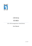
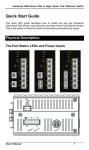
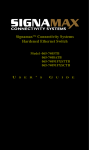
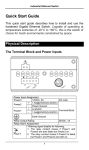
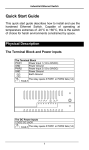
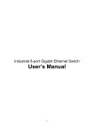
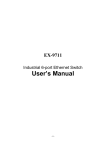
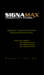
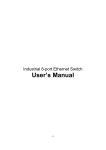
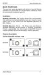
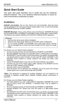
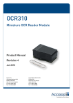
EX42300 series www.etherwan.com Quick Start Guide This quick start guide describes how to install and use the Hardened PoE Ethernet Switch. Capable of operating at temperature extremes of -40°C to +75°C, this is the switch of choice for harsh environments constrained by space. Physical Description The Port Status LEDs 1 EX42300 series LED Power (Green) Fault (Red) www.etherwan.com State Indication Steady Power on. Off Power off. Steady Relay starts alarm. Off Relay non-alarm. 10/100TX Ports Link/Act (Green) PoE (Amber) Steady A valid network connection established. Blinking Transmitting or receiving data. Act stands for Activity. Off No link. Steady Powered Device is connected. Off Powered Device is disconnected. Blinking While Powered Device over 30W. Steady A valid network connection established. Blinking Transmitting or receiving data. Act stands for Activity. Off No link. Gigabit Port Link/Act (Amber) The Terminal Block and Power Inputs 2 EX42300 series www.etherwan.com Power Input Assignment Power1 Power2 + 24/48VDC - Power Ground + 24/48VDC - Power Ground Terminal Block Earth Ground Relay Output Rating 1A @ 250VAC DC Terminal Block Power Input: The DC Terminal Block power input can be used to power up this Switch. DIP Switch Settings DIP No. On Off 1 Port 1 Alarm Enable. Port 1 Alarm Disable. 2 Port 2 Alarm Enable. Port 2 Alarm Disable. 3 Port 3 Alarm Enable. Port 3 Alarm Disable. 4 Port 4 Alarm Enable. Port 4 Alarm Disable. 5 Port 5 Alarm Enable. Port 5 Alarm Disable. Port 6 Alarm Enable. Port 6 Alarm Disable. 7 Broadcast Storm Enable. Broadcast Storm Disable. 8 Jumbo Frame Enable. Jumbo Frame Disable. 6 (Only for EX42315) 3 EX42300 series www.etherwan.com The 10/100Base-TX (PoE) and Gigabit Ethernet Connectors 1. The 10/100Base-TX Connections The following lists the pinouts of 10/100Base-TX ports. Pin 1 2 3 4 5 6 7 8 Signal Name TD+ TD- RD+ PoE PoE RD- PoE PoE Signal Definition Output Transmit Data + Output Transmit Data - Input Receive Data + Positive (VCC+) Positive (VCC+) Input Receive Data - Negative (VCC-) Negative (VCC-) 2. The 10/100/1000Base-TX Connections The following lists the pinouts of 10/100/1000Base-TX ports. 4 EX42300 series Pin 1 2 3 4 5 6 7 8 www.etherwan.com Regular Ports TP0+ TP0- TP1+ TP2+ TP2- TP1- TP3+ TP3- Uplink port Transmit and Receive Data 0 Transmit and Receive Data 0 Transmit and Receive Data 1 Transmit and Receive Data 2 Transmit and Receive Data 2 Transmit and Receive Data 1 Transmit and Receive Data 3 Transmit and Receive Data 3 + - + + - - + - 3. The SFP Socket Connections The SFP socket for Gigabit fiber optic expansion. 4. The 1000Base-SX/LX Connections The fiber port pinouts: The Tx (transmit) port of device I is connected to the Rx (receive) port of device II, and the Rx (receive) port of device I to the Tx (transmit) port of device II. 5. The WDM 1000Base-BX Connections The fiber port pinouts: Only one optical fiber is required to transmit and receive data. 5 EX42300 series www.etherwan.com Functional Description Complies with EN61000-6-2 & EN61000-6-4 EMC Generic standard immunity for industrial environment. Supports 802.3/802.3u/802.3ab/802.3z/802.3x. Auto-negotiation: 10/100/1000Mbps, Full/Half-duplex. Auto MDI/MDIX. 1000Base-SX/LX: Multi mode SC or ST type, Single mode SC type. 1000Base-BX: WDM Single mode SC type. Supports 8192 MAC addresses, 1M bits buffer memory. Supports IEEE802.3az Energy Efficient Ethernet (EEE). High speed, non-blocking four traffic class QoS switch fabric. Supports Jumbo frame up to 10K Bytes on Gigabit port. Enable Broadcast Storm Protection by DIP Switch No. 7 to limit 15,000 packets per second. Port 1~4 support IEEE802.3at Power over Ethernet (PoE) Power Sourcing Equipment (PSE) and provide power up to 30W. Power consumption: 7W Max (Device only, without PoE). PoE power budget: 120W. Power Supply: Redundant 24/48VDC Terminal Block power inputs. Operating temperature ranges from -40°C to 75°C (-40°F to 167°F). Slim design with DIN-Rail mount installation. 6 EX42300 series www.etherwan.com Assembly, Startup, and Dismantling Assembly: Place the switch on the DIN rail from above using the slot. Push the front of the switch toward the mounting surface until it audibly snaps into place. Startup: Connect the supply voltage to start up the switch via the terminal block. Dismantling: Pull out the lower edge and then remove the switch from the DIN rail. 7 EX42300 series www.etherwan.com Preface This manual describes how to install and use the Hardened PoE Ethernet Switch. This switch introduced here is capable of operating at temperature extremes of -40°C to +75°C, this is the switch of choice for harsh environments constrained by space. Port 1 to port 4 on this switch supports IEEE802.3at Power over Ethernet (PoE) Power Sourcing Equipment (PSE) and can detect an IEEE802.3at compliant Powered Device (PD). Using external 48VDC power inputs through Terminal Block, data and power can be transmitted to a Powered Device (PD) over the same twisted-pair Ethernet cable through port 1 to port 4 on the switch. To get the most out of this manual, you should have an understanding of Ethernet networking concepts. In this manual, you will find: Features on the switch Illustrative LED functions Installation instructions Specifications 8 EX42300 series www.etherwan.com Table of Contents QUICK START GUIDE 1 PHYSICAL DESCRIPTION 1 The Port Status LEDs The Terminal Block and Power Inputs DIP Switch Settings The 10/100Base-TX (PoE) and Gigabit Ethernet Connectors FUNCTIONAL DESCRIPTION ASSEMBLY, STARTUP, AND DISMANTLING 1 2 3 4 6 7 PREFACE 8 TABLE OF CONTENTS 9 PRODUCT OVERVIEW 10 HARDENED POE ETHERNET SWITCH PACKAGE CONTENTS PRODUCT HIGHLIGHTS Basic Features 10 10 11 11 FRONT PANEL DISPLAY PHYSICAL PORTS 12 13 INSTALLATION 14 SELECTING A SITE FOR THE SWITCH DIN RAIL MOUNTING CONNECTING TO POWER DC Terminal Block Power Inputs 14 15 16 16 CONNECTING TO YOUR NETWORK 17 Cable Type & Length Cabling 17 18 SPECIFICATIONS 19 9 EX42300 series www.etherwan.com Product Overview Hardened PoE Ethernet Switch Package Contents When you unpack the product package, you shall find the items listed below. Please inspect the contents, and report any apparent damage or missing items immediately to your authorized reseller. This Switch User’s Manual 10 EX42300 series www.etherwan.com Product Highlights Basic Features Complies with EN61000-6-2 & EN61000-6-4 EMC Generic standard immunity for industrial environment. Supports 802.3/802.3u/802.3ab/802.3z/802.3x. Auto-negotiation: 10/100/1000Mbps, Full/Half-duplex. Auto MDI/MDIX. 1000Base-SX/LX: Multi mode SC or ST type, Single mode SC type. 1000Base-BX: WDM Single mode SC type. Supports 8192 MAC addresses, 1M bits buffer memory. Supports IEEE802.3az Energy Efficient Ethernet (EEE). High speed, non-blocking four traffic class QoS switch fabric. 802.1Q VLAN Tag Based Priority, Class of Service. Output Queue Schedule Mode: Weighted Round Robin (WRR) with 4 priority queues. The configurations of QoS are as below: CoS Field Value Packet Count Priority 0 or 1 1 Lowest 2 or 3 2 Low 4 or 5 4 High 6 or 7 8 Highest Supports Jumbo frame up to 10K Bytes on Gigabit port. Enable Broadcast Storm Protection by DIP Switch No. 7 to limit 15,000 packets per second. Port 1~4 support IEEE802.3at Power over Ethernet (PoE) Power Sourcing Equipment (PSE) and provide power up to 30W. Power consumption: 7W Max (Device only, without PoE). PoE power budget: 120W. 11 EX42300 series www.etherwan.com Power Supply: Redundant 24/48VDC Terminal Block power inputs. Operating temperature ranges from -40°C to 75°C (-40°F to 167°F). Slim design with DIN-Rail mount installation. Front Panel Display Power Status (PWR) This LED comes on when the switch is properly connected to power and turned on. Port Status LEDs The LEDs display status for each respective port. 12 EX42300 series LED Power (Green) Fault (Red) www.etherwan.com State Indication Steady Power on. Off Power off. Steady Relay starts alarm. Off Relay non-alarm. 10/100TX Ports Link/Act (Green) PoE (Amber) Steady A valid network connection established. Blinking Transmitting or receiving data. Act stands for Activity. Off No link. Steady Powered Device is connected. Off Powered Device is disconnected. Blinking While Powered Device over 30W. Steady A valid network connection established. Blinking Transmitting or receiving data. Act stands for Activity. Off No link. Gigabit Port Link/Act (Amber) Physical Ports This switch provides: 4 x 10/100Base-TX ports (PoE) + 1-port 10/100/1000Base-TX 4 x 10/100Base-TX ports (PoE) + 1-port 10/100/1000Base-TX + 1-port 1000Base-SX/LX/BX/SFP Connectivity RJ-45 connectors on TX ports ST or SC connector on 1000Base-SX/LX fiber port SC connector on 1000Base-BX fiber port Duplex LC connector on SFP 1000Base-SX/LX/BX fiber transceiver 13 EX42300 series www.etherwan.com Installation This chapter gives step-by-step instructions about how to install the switch: Selecting a Site for the Switch As with any electric device, you should place the switch where it will not be subjected to extreme temperatures, humidity, or electromagnetic interference. Specifically, the site you select should meet the following requirements: - The ambient temperature should be between -40 to 75 degrees Celsius. - The relative humidity should be less than 95 percent, non-condensing. - Surrounding electrical devices should not exceed the electromagnetic field (RFC) standards. - Make sure that the switch receives adequate ventilation. Do not block the ventilation holes on each side of the switch - The power outlet should be within 1.8 meters of the switch. 14 EX42300 series www.etherwan.com DIN Rail Mounting Installation: Place the switch on the DIN rail from above using the slot. Push the front of the switch toward the mounting surface until it audibly snaps into place. Removal: Pull out the lower edge and then remove the switch from the DIN rail. 15 EX42300 series www.etherwan.com Connecting to Power DC Terminal Block Power Inputs Step 1: Connect the DC power cord to the plug-able terminal block on the switch, and then plug it into a standard DC outlet. Step 2: Disconnect the power cord if you want to shut down the switch. Power Input Assignment Power1 Power2 + 24/48VDC - Power Ground + 24/48VDC - Power Ground Terminal Block Earth Ground Relay Output Rating 1A @ 250VAC 16 EX42300 series www.etherwan.com Connecting to Your Network Cable Type & Length It is necessary to follow the cable specifications below when connecting the switch to your network. Use appropriate cables that meet your speed and cabling requirements. Cable Specifications Speed Connector Port Speed Half/Full Duplex Cable Max. Distance 10Base-T RJ-45 10/20 Mbps 2-pair UTP/STP Cat. 3, 4, 5 100 m 100Base-TX RJ-45 100/200 Mbps 2-pair UTP/STP Cat. 5 100 m 1000Base-TX RJ-45 2000 Mbps 100 m 1000Base-SX SC, ST 2000 Mbps 1000Base-SX SC, ST 2000 Mbps 1000Base-LX SC 2000 Mbps 4-pair UTP/STP Cat. 5 MMF (62.5μm) MMF (50μm) SMF (10μm) 1000Base-BX SC 2000 Mbps 1000Base-SX Duplex LC 2000 Mbps 1000Base-LX Duplex LC 2000 Mbps MMF (62.5μm) SMF (9μm) 1000Base-BX Duplex LC 2000 Mbps SMF (9μm) 220 m 2 km 550 m 10, 20, 50 km SMF (10μm) 20, 40 km SFP 17 550 m 2 km 10, 40, 60 km 70 km EX42300 series www.etherwan.com Cabling Step 1: <Note> First, ensure the power of the switch and end devices are turned off. Always ensure that the power is off before any installation. Step 2: Prepare cable with corresponding connectors for each type of port in use. <Note> To connect two regular RJ-45 ports between switches or hubs, you need a straight or cross-over cable. Step 3: Consult the previous section for cabling requirements based on connectors and speed. Step 4: Connect one end of the cable to the switch and the other end to a desired device. Step 5: Once the connections between two end devices are made successfully, turn on the power and the switch is operational. 18 EX42300 series www.etherwan.com Specifications Hardened PoE Ethernet Switch Applicable Standards Forwarding Rate 10Base-T: 100Base-TX: 1000Base-T/SX/LX: Performance Cable 10Base-T: 100Base-TX: 1000Base-T: 1000Base-SX/LX: LED Indicators Dimensions Net Weight Power Power Consumption PoE Power Budget Operating Temperature Storage Temperature Humidity EMI 4 x 10/100Base-TX ports (PoE) + 1-port 10/100/1000Base-TX + 1-port 1000Base-SX/LX/BX/SFP IEEE 802.3 10Base-T IEEE 802.3u 100Base-TX IEEE 802.3ab 1000Base-T IEEE 802.3z 1000Base-SX/LX IEEE 802.1x Full-duplex Flow Control IEEE 802.1az Energy Efficient Ethernet IEEE 802.1p Quality of Service (QoS) 10 / 20Mbps half / full-duplex 100 / 200Mbps half / full-duplex 2000Mbps full-duplex 148,80pps for 10Mbps 148,810pps for 100Mbps 1,488,100pps for 1000Mbps 2-pair UTP/STP Cat. 3, 4, 5 2-pair UTP/STP Cat. 5 4-pair UTP/STP Cat. 5 MMF (50 or 62.5μm), SMF (9 or10μm) Per unit – Power, Fault Per port – Link/Act, PoE (For PoE ports) 30mm (W) × 100mm (D) × 149mm (H) (1.18” (W) × 4” (D) × 5.96” (H)) 0.34Kg (0.75lb.) Terminal Block: 24-48VDC 7W Max (Device only, without PoE) 120W -40°C to 75°C (-40°F to 167°F) -40°C to 85°C (-40°F to 185°F) 5%-95% non-condensing FCC Part 15 Class A, VCCI Class A EN61000-6-4 EN55022 Class A 19 EX42300 series EMS Environmental Test Compliance www.etherwan.com EN61000-6-2: EN61000-4-2 (ESD Standard) EN61000-4-3 (Radiated RFI Standards) EN61000-4-4 (Burst Standards) EN61000-4-5 (Surge Standards) EN61000-4-6 (Induced RFI Standards) EN61000-4-8 (Magnetic Field Standards) IEC60068-2-6 Fc (Vibration) IEC60068-2-27 Ea (Shock) FED STD 101C Method 5007.1 (Free Fall w/ package) 20