1
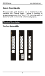
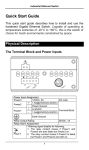
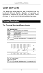
EX42905/EX42914 series www.etherwan.com Quick Start Guide This quick start guide describes how to install and use the Hardened Gigabit Ethernet Switch. Capable of operating at temperature extremes of -40°C to 75°C, this is the Switch of choice for harsh environments constrained by space. Physical Description The Port Status LEDs 1 EX42905/EX42914 series LED PWR 10/100 1000 www.etherwan.com State Steady Off Indication Device is powered up. Device is powered off. A valid network connection established at 10 or Steady 100Mbps. Flashing Transmitting or receiving data. Steady A valid network connection established at 1000Mbps. Off The port is transferring at 10Mbps If this LED is dark. The Terminal Block and Power Input The Terminal Block PWR Power Input GND Power Ground Earth Ground DC Terminal Block Power Input: The DC Terminal Block power input can be used to power up this Switch / Media Converter. CAUTION: This equipment is designed to permit the connection of the earthed conductor of the DC supply circuit to the earthing conductor at the equipment. If this connection is made, all of the following conditions must be met: This equipment shall be connected to directly to the DC supply system earthing electrode conductor or to a bonding jumper from an earthing terminal bar or bus to which the DC supply system earthing electrode conductor is connected. 2 EX42905/EX42914 series www.etherwan.com This equipment shall be located in the same immediate area (such as, adjacent cabinets) as any other equipment that has a connection between the earthed conductor of the same DC supply circuit and the earthing conductor, and also the point of earthing of the DC system. The DC system shall not be earthed elsewhere. The DC supply source is to be located within the same premises as the equipment. Switching or disconnecting devices shall not be in the earthed circuit conductor between the DC source and the point of connection of the earthing electrode conductor. The 10/100/1000Base-TX and 1000Base-SX/LX/BX Connectors 1. The 10/100/1000Base-TX Connections The following lists the pinouts of 10/100/1000Base-TX ports. Pin 1 Regular Ports TP0+ Uplink port Transmit and Receive Data 0 + 2 TP0- Transmit and Receive Data 0 - 3 TP1+ Transmit and Receive Data 1 + 4 TP2+ Transmit and Receive Data 2 + 5 TP2- Transmit and Receive Data 2 - 6 TP1- Transmit and Receive Data 1 - 7 TP3+ Transmit and Receive Data 3 + 8 TP3- Transmit and Receive Data 3 - 3 EX42905/EX42914 series www.etherwan.com 2. The 1000Base-SX/LX Connections The fiber port pinouts: The Tx (transmit) port of device I is connected to the Rx (receive) port of device II, and the Rx (receive) port of device I to the Tx (transmit) port of device II. 3. The WDM 1000Base-BX Connections The fiber port pinouts: Only one Single mode or Multi mode optical fiber is required to transmit and receive data. Functional Description Complies with EN61000-6-2 & EN61000-6-4 EMC Generic standard immunity for industrial environment. Supports 802.3/802.3u/802.3ab/802.3z/802.3x. Auto-negotiation: 10/100/1000Mbps, Full/Half-duplex. Auto MDI/MDIX. 1000Base-SX/LX: Multi mode SC or ST type, Single mode SC or ST type. 1000Base-BX: WDM Multi mode or Single mode SC type. Supports 8192 MAC addresses, 1M bits buffer memory. Jumbo frame supported up to 10K bytes. IEEE802.3az Energy Efficient Ethernet (EEE) supported. Quality of Service (QoS) supported based on layer 2 priorities. Power consumption: 6.5W Max. 0.25A @ 24VDC. Power supply: DC Terminal Block power input, 12-48VDC. 4 EX42905/EX42914 series www.etherwan.com -40°C to 75°C (-40°F to 167°F) operating temperature range. Tested for functional operation @ -40°C to 85°C (-40°F to 185°F). Metal compact DIN-Rail industrial case design. 5 EX42905/EX42914 series www.etherwan.com Assembly, Startup, and Dismantling Assembly: Place the device on the DIN-Rail from above using the slot. Push the front of the device toward the mounting surface until it audibly snaps into place. Startup: Connect the supply voltage to start up the device via the terminal block. Dismantling: Pull out the lower edge and then remove the device from the DIN-Rail. 6 EX42905/EX42914 series www.etherwan.com Preface A member of the growing family of rugged switches, this switch addresses a need for a smaller switch. This switch provides an affordable solution for rugged and outdoor environment, transportation road-side cabinet, industrial floor shop, multitenant dwellings or Fiber To The Home (FTTH) applications. Capable of operating at temperature extremes of -40°C to 75°C, this is the switch of choice for harsh environments constrained by space. Plug-and-Play Solution: The switch is a plug-and-play Gigabit Ethernet Switch in compact size. It doesn't have any complicated software to set up. This manual describes how to install and use the hardened compact Gigabit Ethernet Switch. This switch integrates full wire speed switching technology. This switch brings the answer to complicated hardened networking environments. To get the most out of this manual, you should have an understanding of Ethernet networking concepts. In this manual, you will find: Features on the switch Illustrative LED functions Installation instructions Specifications 7 EX42905/EX42914 series www.etherwan.com Table of Contents QUICK START GUIDE 1 PHYSICAL DESCRIPTION 1 The Port Status LEDs The Terminal Block and Power Input The 10/100/1000Base-TX and 1000Base-SX/LX/BX Connectors FUNCTIONAL DESCRIPTION ASSEMBLY, STARTUP, AND DISMANTLING 1 2 3 4 6 PREFACE 7 TABLE OF CONTENTS 8 PRODUCT OVERVIEW 9 HARDENED GIGABIT ETHERNET SWITCH PACKAGE CONTENTS PRODUCT HIGHLIGHTS Basic Features 9 9 10 10 FRONT PANEL DISPLAY PHYSICAL PORTS 11 12 INSTALLATION 13 SELECTING A SITE FOR THE SWITCH DIN RAIL MOUNTING CONNECTING TO POWER DC Terminal Block Power Inputs 13 14 15 15 CONNECTING TO YOUR NETWORK 17 Cable Type & Length Cabling 17 18 SPECIFICATIONS 19 8 EX42905/EX42914 series www.etherwan.com Product Overview Hardened Gigabit Ethernet Switch Package Contents When you unpack the product package, you shall find the items listed below. Please inspect the contents, and report any apparent damage or missing items immediately to your authorized reseller. This Switch User’s Manual 9 EX42905/EX42914 series www.etherwan.com Product Highlights Basic Features Complies with EN61000-6-2 & EN61000-6-4 EMC Generic standard immunity for industrial environment. Supports 802.3/802.3u/802.3ab/802.3z/802.3x. Auto-negotiation: 10/100/1000Mbps, Full/Half-duplex. Auto MDI/MDIX. 1000Base-SX/LX: Multi mode SC or ST type, Single mode SC or ST type. 1000Base-BX: WDM Multi mode or Single mode SC type. Supports 8192 MAC addresses, 1M bits buffer memory. Jumbo frame supported up to 10K bytes. IEEE802.3az Energy Efficient Ethernet (EEE) supported. Quality of Service (QoS) supported based on layer 2 priorities. Power consumption: 6.5W Max. 0.25A @ 24VDC. Power supply: DC Terminal Block power input, 12-48VDC. -40°C to 75°C (-40°F to 167°F) operating temperature range. Tested for functional operation @ -40°C to 85°C (-40°F to 185°F). Metal compact DIN-Rail industrial case design. 10 EX42905/EX42914 series www.etherwan.com Front Panel Display Power Status (PWR) This LED comes on when the switch is properly connected to power and turned on. Port Status LEDs The LEDs display status for each respective port. LED PWR 10/100 1000 State Steady Off Indication Device is powered up. Device is powered off. A valid network connection established at 10 or Steady 100Mbps. Flashing Transmitting or receiving data. Steady A valid network connection established at 1000Mbps. Off The port is transferring at 10Mbps If this LED is dark. 11 EX42905/EX42914 series www.etherwan.com Physical Ports This switch provides: Five 10/100/1000Base-TX ports Four 10/100/1000Base-TX ports + one 1000Base-SX/LX/BX port Connectivity: RJ-45 connectors SC or ST connector on 1000Base-SX/LX fiber port SC connector on 1000Base-BX fiber port 12 EX42905/EX42914 series www.etherwan.com Installation This chapter gives step-by-step instructions about how to install the switch: Selecting a Site for the Switch As with any electric device, you should place the switch where it will not be subjected to extreme temperatures, humidity, or electromagnetic interference. Specifically, the site you select should meet the following requirements: The ambient temperature should be between -40 to 75 degrees Celsius. The relative humidity should be less than 95 percent, non-condensing. Surrounding electrical devices should not exceed the electromagnetic field (RFC) standards. Make sure that the switch receives adequate ventilation. Do not block the ventilation holes on each side of the switch The power outlet should be within 1.8 meters of the switch. 13 EX42905/EX42914 series www.etherwan.com DIN Rail Mounting Installation: Place the switch on the DIN rail from above using the slot. Push the front of the switch toward the mounting surface until it audibly snaps into place. Removal: Pull out the lower edge and then remove the switch from the DIN rail. 14 EX42905/EX42914 series www.etherwan.com Connecting to Power DC Terminal Block Power Inputs Step 1: Connect the DC power cord to the plug-able terminal block on the switch, and then plug it into a standard DC outlet. Step 2: Disconnect the power cord if you want to shut down the switch. The Terminal Block PWR Power Input GND Power Ground Earth Ground CAUTION: This equipment is designed to permit the connection of the earthed conductor of the DC supply circuit to the earthing conductor at the equipment. If this connection is made, all of the following conditions must be met: This equipment shall be connected to directly to the DC supply system earthing electrode conductor or to a bonding jumper from an earthing terminal bar or bus to which the DC supply system earthing electrode conductor is connected. This equipment shall be located in the same immediate area (such as, adjacent cabinets) as any other equipment that has a connection between the earthed conductor of the same DC supply circuit and the earthing conductor, and also the point of 15 EX42905/EX42914 series www.etherwan.com earthing of the DC system. The DC system shall not be earthed elsewhere. The DC supply source is to be located within the same premises as the equipment. Switching or disconnecting devices shall not be in the earthed circuit conductor between the DC source and the point of connection of the earthing electrode conductor. 16 EX42905/EX42914 series www.etherwan.com Connecting to Your Network Cable Type & Length It is necessary to follow the cable specifications below when connecting the switch to your network. Use appropriate cables that meet your speed and cabling requirements. Cable Specifications Speed Connector Port Speed Half/Full Duplex Cable Max. Distance 10Base-T RJ-45 10/20 Mbps 2-pair UTP/STP Cat. 3, 4, 5 100 m 100Base-TX RJ-45 100/200 Mbps 2-pair UTP/STP Cat. 5 100 m 1000Base-T RJ-45 2000 Mbps 4-pair UTP/STP Cat. 5 100 m 1000Base-SX SC, ST 2000 Mbps MMF (50 or 62.5μm) 550 m 1000Base-SX SC 2000 Mbps MMF (50 or 62.5μm) 2 km 1000Base-LX SC 2000 Mbps SMF (9 or 10μm) 10 or 20 km 1000Base-BX SC 2000 Mbps SMF (9 or 10μm) 20 km 17 EX42905/EX42914 series www.etherwan.com Cabling Step 1: <Note> First, ensure the power of the switch and end devices are turned off. Always ensure that the power is off before any installation. Step 2: Prepare cable with corresponding connectors for each type of port in use. <Note> To connect two regular RJ-45 ports between switches or hubs, you need a straight or cross-over cable. Step 3: Consult the previous section for cabling requirements based on connectors and speed. Step 4: Connect one end of the cable to the switch and the other end to a desired device. Step 5: Once the connections between two end devices are made successfully, turn on the power and the switch is operational. 18 EX42905/EX42914 series www.etherwan.com Specifications Hardened Compact Switch Applicable Standards Forwarding Rate 10Base-T: 100Base-TX: 1000Base-T/SX/LX/BX: Performance Cable 10Base-T: 100Base-TX: 1000Base-T: 100Base-SX/LX/BX: LED Indicators Dimensions Net Weight Power Operating Voltage & Max. Current Consumption Power Consumption Operating Temperature Storage Temperature Humidity EMI 10/100/1000Base-TX auto-negotiating ports with RJ-45 connectors, 1000Base-SX/LX/BX fiber port IEEE 802.3 10Base-T IEEE 802.3u 100Base-TX IEEE 802.3ab 1000Base-T IEEE 802.3z 1000Base-SX/LX 10 / 20Mbps half / full-duplex 100 / 200Mbps half / full-duplex 2000Mbps full-duplex 148,80pps for 10Mbps 148,810pps for 100Mbps 1,488,100pps for 1000Mbps 2-pair UTP/STP Cat. 3, 4, 5 2-pair UTP/STP Cat. 5 4-pair UTP/STP Cat. 5 Up to 100m (328ft) MMF (50 or 62.5μm), SMF (9 or10μm) Per unit – Power status (PWR) Per port – 10/100/1000TX: 10/100, 1000 1000SX/LX/BX: 1000 30mm (W) × 82mm (D) × 114mm (H) (1.18” (W) × 3.23” (D) × 4.49” (H)) 0.34Kg (0.75lb.) Terminal Block: 12-48VDC 0.25A @ 24VDC 6.5W Max. -40°C to 75°C (-40°F to 167°F) Tested for functional operation @ -40°C to 85°C (-40°F to 185°F) -40°C to 85°C (-40°F to 185°F) 5%-95% non-condensing FCC Part 15 Class A, VCCI EN61000-6-4: EN55022, EN61000-3-2, EN61000-3-3 19 EX42905/EX42914 series EMS Environmental Test Compliance www.etherwan.com EN61000-6-2: EN61000-4-2 (ESD Standard) EN61000-4-3 (Radiated RFI Standards) EN61000-4-4 (Burst Standards) EN61000-4-5 (Surge Standards) EN61000-4-6 (Induced RFI Standards) EN61000-4-8 (Magnetic Field Standards) IEC60068-2-6 Fc (Vibration Resistance) IEC60068-2-27 Ea (Shock) FED STD 101C Method 5007.1 (Free Fall w/ package) 20