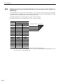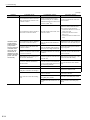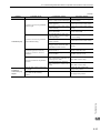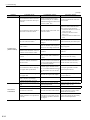
1
8
Troubleshooting
8.1 Alarm Displays . . . . . . . . . . . . . . . . . . . . . . . . . . . . . . . . . . . . . . . . . . . . . . 8-2
8.1.1 List of Alarms . . . . . . . . . . . . . . . . . . . . . . . . . . . . . . . . . . . . . . . . . . . . . . . . . . . . . . . . 8-2
8.1.2 Troubleshooting of Alarms . . . . . . . . . . . . . . . . . . . . . . . . . . . . . . . . . . . . . . . . . . . . . . 8-6
8.2 Warning Displays . . . . . . . . . . . . . . . . . . . . . . . . . . . . . . . . . . . . . . . . . . . 8-23
8.2.1 List of Warnings . . . . . . . . . . . . . . . . . . . . . . . . . . . . . . . . . . . . . . . . . . . . . . . . . . . . . 8-23
8.2.2 Troubleshooting of Warnings . . . . . . . . . . . . . . . . . . . . . . . . . . . . . . . . . . . . . . . . . . . 8-25
8.3 Monitoring Communication Data on Occurrence of an Alarm
or Warning . . . . . . . . . . . . . . . . . . . . . . . . . . . . . . . . . . . . . . . . . . . . . . . 8-30
Troubleshooting
8.4 Troubleshooting Malfunction Based on Operation
and Conditions of the Servomotor . . . . . . . . . . . . . . . . . . . . . . . . . . . . . 8-31
8
8-1
8 Troubleshooting
8.1.1 List of Alarms
8.1
Alarm Displays
The following sections describe troubleshooting in response to alarm displays.
The alarm name, alarm meaning, alarm stopping method, and alarm reset capability are listed in order of the
alarm numbers in 8.1.1 List of Alarms.
The causes of alarms and troubleshooting methods are provided in 8.1.2 Troubleshooting of Alarms.
8.1.1
List of Alarms
This section provides list of alarms.
Servomotor Stopping Method
If an alarm occurs, the servomotor can be stopped by doing either of the following operations.
Gr.1: The servomotor is stopped according to the setting in Pn001.0 if an alarm occurs. Pn001.0 is factory-set
to stop the servomotor by applying the DB.
Gr.2: The servomotor is stopped according to the setting in Pn00B.1 if an alarm occurs. Pn00B.1 is factory-set
to stop the servomotor by setting the speed reference to "0." The servomotor under force control will
always use the Gr.1 method to stop. By setting Pn00B.1 to 1, the servomotor stops using the same
method as Gr.1. When coordinating a number of servomotors, use this stopping method to prevent
machine damage that may result due to differences in the stop method.
Alarm Reset
Available:Removing the cause of alarm and then executing the alarm reset can clear the alarm.
N/A:Executing the alarm reset cannot clear the alarm.
Alarm
Number
8-2
Alarm Name
Meaning
Servomotor
Stopping
Method
Alarm
Reset
A.020
Parameter Checksum
Error 1
The data of the parameter in the SERVOPACK is
incorrect.
Gr.1
N/A
A.021
Parameter Format Error 1
The data of the parameter in the SERVOPACK is
incorrect.
Gr.1
N/A
A.022
System Checksum Error 1
The data of the parameter in the SERVOPACK is
incorrect.
Gr.1
N/A
A.030
Main Circuit Detector Error Detection data for main circuit is incorrect.
Gr.1
Available
A.040
Parameter Setting Error 1
The parameter setting is outside the setting range.
Gr.1
N/A
A.041
Encoder Output Pulse
Setting Error
The encoder output resolution (Pn281) is outside the
setting range or does not satisfy the setting conditions.
Gr.1
N/A
A.042
Parameter Combination
Error
Combination of some parameters exceeds the setting
range.
Gr.1
N/A
A.04A
Parameter Setting Error 2
Bank member/bank data setting is incorrect.
Gr.1
N/A
A.050
Combination Error
The SERVOPACK and the servomotor capacities do
not match each other.
Gr.1
Available
A.051
Unsupported Device Alarm The device unsupported was connected.
Gr.1
N/A
A.080
Linear Scale Pitch Setting
Error
The setting of the linear scale pitch (Pn282) has not
been changed from the default setting.
Gr.1
N/A
A.0b0
Cancelled Servo ON
Command Alarm
The servo ON command (SV_ON) was sent from the
host controller after executing a utility function that
turns ON servomotor.
Gr.1
Available
A.100
Overcurrent or Heat Sink
Overheated
An overcurrent flowed through the IGBT or the heat
sink of the SERVOPACK was overheated.
Gr.1
N/A
A.300
Regeneration Error
Regenerative circuit or regenerative resistor is faulty.
Gr.1
Available
A.320
Regenerative Overload
Regenerative energy exceeds regenerative resistor
capacity.
Gr.2
Available
8.1 Alarm Displays
Alarm
Number
Alarm Name
Meaning
Alarm
Reset
A.330
Main Circuit Power
Supply Wiring Error
• Setting of AC input/DC input is incorrect.
• Power supply wiring is incorrect.
Gr.1
Available
A.400
Overvoltage
Main circuit DC voltage is excessively high.
Gr.1
Available
A.410
Undervoltage
Main circuit DC voltage is excessively low.
Gr.2
Available
A.450
Main-Circuit
Capacitor Overvoltage
The capacitor of the main circuit has deteriorated or is
faulty.
Gr.1
N/A
A.510
Overspeed
The servomotor speed is above the maximum speed.
Gr.1
Available
A.511
Overspeed of Encoder
Output Pulse Rate
The motor speed upper limit of the set encoder output
resolution (Pn281) is exceeded.
Gr.1
Available
A.520
Vibration Alarm
Incorrect vibration at the motor speed was detected.
Gr.1
Available
A.521
Autotuning Alarm
Vibration was detected while performing tuning-less
function.
Gr.1
Available
A.550
Maximum Speed Setting
Error
The Pn385 setting is greater than the maximum speed.
Gr.1
Available
A.710
Overload: High Load
The servomotor was operating for several seconds to
several tens of seconds under a force largely exceeding
ratings.
Gr.2
Available
A.720
Overload: Low Load
The servomotor was operating continuously under a
force exceeding ratings.
Gr.1
Available
A.730
A.731
Dynamic Brake Overload
When the dynamic brake was applied, moving energy
exceeded the capacity of dynamic brake resistor.
Gr.1
Available
A.740
Overload of Surge
Current Limit Resistor
The main circuit power was frequently turned ON and
OFF.
Gr.1
Available
A.7A0
Heat Sink Overheated
The heat sink of the SERVOPACK exceeded 100°C.
Gr.2
Available
A.7AB
Built-in Fan in SERVOPACK Stopped
The fan inside the SERVOPACK stopped.
Gr.1
Available
A.820
Encoder Checksum Error
The checksum results of linear scale memory is incorrect.
Gr.1
N/A
A.840
Encoder Data Error
Data in the linear scale is incorrect.
Gr.1
N/A
A.850
Encoder Overspeed
The linear scale was moving at high speed when the
power was turned ON.
Gr.1
N/A
A.860
Encoder Overheated
The internal temperature of linear scale is too high.
Gr.1
N/A
A.890
Encoder Scale Error
A linear scale fault occurred
Gr.1
N/A
A.891
Encoder Module Error
Linear scale is faulty.
Gr.1
N/A
A.A
*1
SERVOPACK: Command
Option Module Alarms
−
−
A.b31
Current Detection Error 1
The current detection circuit for phase U is faulty.
Gr.1
N/A
A.b32
Current Detection Error 2
The current detection circuit for phase V is faulty.
Gr.1
N/A
A.b33
Current Detection Error 3
The detection circuit for the current is faulty.
Gr.1
N/A
A.b6A
MECHATROLINK
Communications
ASIC Error 1
ASIC error occurred in the MECHATROLINK communications.
Gr.1
N/A
A.b6b
MECHATROLINK
Communications
ASIC Error 2
ASIC error occurred in the MECHATROLINK communications.
Gr.2
N/A
A.bF0
System Alarm 0
"Internal program error 0" of the SERVOPACK
occurred.
Gr.1
N/A
A.bF1
System Alarm 1
"Internal program error 1" of the SERVOPACK
occurred.
Gr.1
N/A
−
Troubleshooting
(cont’d)
Servomotor
Stopping
Method
8
8-3
8 Troubleshooting
8.1.1 List of Alarms
(cont’d)
Alarm
Number
8-4
Alarm Name
Meaning
Servomotor
Stopping
Method
Alarm
Reset
A.bF2
System Alarm 2
"Internal program error 2" of the SERVOPACK
occurred.
Gr.1
N/A
A.bF3
System Alarm 3
"Internal program error 3" of the SERVOPACK
occurred.
Gr.1
N/A
A.bF4
System Alarm 4
"Internal program error 4" of the SERVOPACK
occurred.
Gr.1
N/A
A.C10
Servo Overrun Detected
The servomotor ran out of control.
Gr.1
Available
A.C20
Phase Detection Error
The detection of the phase is incorrect.
Gr.1
N/A
A.C21
Hall Sensor Error
The hall sensor is faulty.
Gr.1
N/A
A.C22
Phase Information
Disagreement
The phase information does not match.
Gr.1
N/A
A.C50
Polarity Detection Error
The polarity detection failed.
Gr.1
N/A
A.C51
Overtravel Detection at
Polarity Detection
The overtravel signal was detected at polarity detection.
Gr.1
Available
A.C52
Polarity Detection
Uncompleted
The servomotor was turned ON under the condition of
polarity detection uncompleted.
Gr.1
Available
A.C53
Out of Range for Polarity
Detection
The moving distance exceeded the set value of Pn48E
during polarity detection.
Gr.1
N/A
A.C54
Polarity Detection Error 2
The polarity detection failed.
Gr.1
N/A
A.C80
Absolute Encoder Clear
Error
The data for the absolute linear scale was not properly
cleared or set.
Gr.1
N/A
A.C90
Encoder Communications
Error
Communications between the SERVOPACK and the
linear scale is not possible.
Gr.1
N/A
A.C91
Encoder Communications
Position Data Error
A linear scale position data calculation error occurred.
Gr.1
N/A
A.C92
Encoder Communications
Timer Error
An error occurs in the communications timer between
the linear scale and the SERVOPACK.
Gr.1
N/A
A.CA0
Encoder Parameter Error
Linear scale parameters are faulty.
Gr.1
N/A
A.Cb0
Encoder Echoback Error
Contents of communications with linear scale are
incorrect.
Gr.1
N/A
A.d00
Position Error Overflow
Position error exceeded the value of excessive position
error alarm level (Pn520) when the servomotor power
is ON.
Gr.1
Available
A.d01
Position Error Overflow
Alarm at Servo ON
This alarm occurs if the servomotor power is turned
ON when the position error is greater than the set
value of Pn526 while the servomotor power is OFF.
Gr.1
Available
A.d02
Position Error Overflow
Alarm by Speed Limit at
Servo ON
When the position errors remain in the error counter,
Pn584 limits the speed if the servomotor power is
turned ON. If Pn584 limits the speed in such a state,
this alarm occurs when position references are input
and the number of position errors exceeds the value set
for the excessive position error alarm level (Pn520).
Gr.2
Available
A.d30
Position Data Overflow
The position feedback data exceeded ±1879048192.
Gr.1
N/A
A.E02
MECHATROLINK
Internal Synchronization
Error 1
Synchronization error during MECHATROLINK
communications with the SERVOPACK.
Gr.1
Available
A.E40
MECHATROLINK
Transmission Cycle
Setting Error
The setting of the MECHATROLINK transmission
cycle is out of the allowable range.
Gr.2
Available
A.E41
MECHATROLINK
Communications Data
Size Setting Error
The setting of the MECHATROLINK communications data size is incorrect.
Gr.2
Available
8.1 Alarm Displays
Alarm
Number
Alarm Name
Meaning
Alarm
Reset
A.E42
MECHATROLINK Station
Address Setting Error
The setting of the MECHATROLINK station address
is incorrect.
Gr.2
N/A
A.E50
MECHATROLINK
Synchronization Error
A synchronization error occurs during MECHATROLINK communications.
Gr.2
Available
A.E51
MECHATROLINK
Synchronization Failed
A synchronization failure occurs in MECHATROLINK communications.
Gr.2
Available
A.E60
MECHATROLINK
Communications Error
(Reception error)
A communications error occurs continuously during
MECHATROLINK communications.
Gr.2
Available
A.E61
MECHATROLINK
Transmission Cycle Error
(Synchronization interval
error)
The transmission cycle fluctuates during MECHATROLINK communications.
Gr.2
Available
A.E62
MECHATROLINK
Communications Error
(FCS error)
Communications error occurs continuously during
MECHATROLINK communications.
Gr.2
Available
A.E63
MECHATROLINK
Synchronization Frame
Not Received Alarm
Synchronization frames are not received continuously
during MECHATROLINK communications.
Gr.2
Available
A.E71
Safety Option Module
Detection Failure
Detection of the safety option module failed.
Gr.1
N/A
A.E74
Unsupported Safety
Option Module
An unsupported safety option module was connected.
Gr.1
N/A
A.E75
Unsupported Feedback
Option Module
An unsupported feedback option module was connected.
Gr.1
N/A
–
–
SERVOPACK: Safety
A.E81*2 Module Alarm
–
A.EA2
DRV Alarm 2
A SERVOPACK DRV alarm 0 occurs.
(SERVOPACK WDC error)
Gr.2
Available
A.Eb1
Safety Function Signal
Input Timing Error
Gr.1
N/A
A.Eb
SERVOPACK: Safety
Module Alarms
–
–
–
SERVOPACK: Safety
Module Alarms
–
–
–
*2
A.EC
*2
The safety function signal input timing is faulty.
A.Ed1
Command Execution
Timeout
A timeout error occurred when using a MECHATROLINK command.
Gr.2
Available
A.F10
Main Circuit Cable Open
Phase
With the main power supply ON, voltage was low for
more than 1 second in phase R, S, or T.
Gr.2
Available
System Alarm
Internal program error occurred in the SERVOPACK
−
N/A
−
N/A
−
N/A
−
N/A
−
−
FL-1*3
FL-2*3
CPF00
Digital Operator
Transmission Error 1
CPF01
Digital Operator
Transmission Error 2
A.− −
Not an error
Digital operator (JUSP-OP05A-1-E) fails to communicate with the SERVOPACK (e.g., CPU error).
Normal operation status
∗1. These alarms occur in SERVOPACKs with command option modules.
For details, refer to the manual for the command option module that is connected.
∗2. These alarms occur in SERVOPACKs with safety modules.
For details, refer to Σ-V Series User’s Manual, Safety Module (No.: SIEP C720829 06).
∗3. These alarms are not stored in the alarm history and are displayed only in the panel display.
Troubleshooting
(cont’d)
Servomotor
Stopping
Method
8
8-5
8 Troubleshooting
8.1.2 Troubleshooting of Alarms
8.1.2
Troubleshooting of Alarms
If an error occurs in servo drives, an alarm display such as A.
play.
and CPF
will appear on the panel dis-
Refer to the following table to identify the cause of an alarm and the action to be taken.
Contact your Yaskawa representative if the problem cannot be solved by the described corrective action.
Alarm Number:
Alarm Name
(Alarm Description)
A.020:
Parameter Checksum
Error 1
(The parameter data in
the SERVOPACK is
incorrect.)
A.021:
Parameter Format
Error 1
(The parameter data in
the SERVOPACK is
incorrect.)
A.022:
System Checksum
Error 1
(The parameter data in
the SERVOPACK is
incorrect.)
A.030:
Main Circuit Detector
Error
A.040:
Parameter Setting
Error 1
(The parameter setting
was out of the setting
range.)
8-6
Cause
Investigative Actions
Corrective Actions
The power supply voltage suddenly dropped.
Measure the power supply voltage.
Set the power supply voltage within
the specified range, and set Fn005
to initialize the parameter.
The power supply went OFF
while changing a parameter setting.
Check the circumstances when the
power supply went OFF.
Set Fn005 to initialize the parameter
and then set the parameter again.
The SERVOPACK may be faulty.
The number of times that parame- Check to see if the parameters were Replace the SERVOPACK.
ters were written exceeded the
frequently changed through the host
Reconsider the method of writing
limit.
controller.
parameters.
Malfunction caused by noise
from the AC power supply or
grounding line, static electricity
noise, etc.
Turn the power supply ON and OFF
Take countermeasures against
several times. If the alarm still
occurs, there may be noise interfer- noise.
ence.
Gas, water drops, or cutting oil
entered the SERVOPACK and
caused failure of the internal
components.
Check the installation conditions.
A SERVOPACK fault occurred.
Turn the power supply ON and OFF
several times. If the alarm still
The SERVOPACK may be faulty.
occurs, the SERVOPACK may be
Replace the SERVOPACK.
faulty.
The software version of SERVOPACK that caused the alarm is
older than that of the written
parameter.
Write the parameter of another
Check Fn012 to see if the set softSERVOPACK of the same model
ware version agrees with that of the
with the same software version.
SERVOPACK. If not, an alarm may
Then turn the power OFF and then
occur.
ON again.
A SERVOPACK fault occurred.
−
The SERVOPACK may be faulty.
Replace the SERVOPACK.
The power supply voltage suddenly dropped.
Measure the power supply voltage.
The SERVOPACK may be faulty.
Replace the SERVOPACK.
The power supply went OFF
while setting an utility function.
Check the circumstances when the
power supply went OFF.
The SERVOPACK may be faulty.
Replace the SERVOPACK.
A SERVOPACK fault occurred.
Turn the power supply ON and OFF
The SERVOPACK may be faulty.
several times. If the alarm still
occurs, the SERVOPACK may be
Replace the SERVOPACK.
faulty.
A SERVOPACK fault occurred.
−
The SERVOPACK and servomoCheck the combination of SERVOtor capacities do not match each
PACK and servomotor capacities.
other.
The SERVOPACK may be faulty.
Replace the SERVOPACK.
The SERVOPACK may be faulty.
Replace the SERVOPACK.
Select the proper combination of
SERVOPACK and servomotor
capacities.
The SERVOPACK may be faulty.
Replace the SERVOPACK.
A SERVOPACK fault occurred.
−
The parameter setting is out of
the setting range.
Check the setting ranges of the
Set the parameter to a value within
parameters that have been changed. the setting range.
Check the electronic gear ratio. The Set the electronic gear ratio in the
The electronic gear ratio is out of ratio must satisfy:
range: 0.001< (Pn20E/Pn210)
the setting range.
< 4000.
0.001< (Pn20E/Pn210) < 4000.
8.1 Alarm Displays
(cont’d)
A.041:
Encoder Output Pulse
Setting Error
A.042:*1
Parameter
Combination Error
A.04A:
Parameter Setting
Error 2
Cause
Investigative Actions
The encoder output resolution
(Pn281) is out of the setting range
Check the parameter Pn281.
and does not satisfy the setting
conditions.
Set Pn281 to a correct value.
The speed of program JOG operation (Fn004) is lower than the
setting range after having
Check if the detection conditions*
changed the electronic gear ratio are satisfied.
(Pn20E/Pn210) or the servomotor.
Decrease the setting of the electronic gear ratio (Pn20E/Pn210).
The speed of program JOG operation (Fn004) is lower than the
setting range after having
Check if the detection conditions*
changed the setting of the proare satisfied.
gram JOG movement speed
(Pn585).
Increase the setting of the program
JOG movement speed (Pn585).
The moving speed of advanced
autotuning is lower than the setting range after having changed
the electronic gear ratio (Pn20E/
Pn210) or the servomotor.
Check if the detection conditions*
are satisfied.
Decrease the setting of the electronic gear ratio (Pn20E/Pn210).
For a 4-byte parameter bank, no
registration in two consecutive
bytes for two bank members.
–
Change the number of bytes for
bank members to an appropriate
value.
The total amount of bank data
exceeds 64. (Pn900 × Pn901 >
64)
–
Reduce the total amount of bank
data to 64 or less.
Check the capacities to see if they
The SERVOPACK and servomo- satisfy the following condition:
tor capacities do not match each
1
Servomotor capacity
other.
≤
≤4
4
SERVOPACK capacity
A.050:
Combination Error
(The SERVOPACK and
servomotor capacities do A linear scale fault occurred.
not correspond.)
A.051:
Unsupported Device
Alarm
Corrective Actions
Select the proper combination of
SERVOPACK and servomotor
capacities.
Replace the linear scale and see if
the alarm occurs again.
Replace the linear scale.
A SERVOPACK fault occurred.
−
The SERVOPACK may be faulty.
Replace the SERVOPACK.
The parameters of the motor
parameter file are not written in
the linear scale. (Only when not
using serial converter units)
Check if the parameters of the
motor parameter file are written in
the linear scale.
Write the parameters of the motor
parameter file in the linear scale.
An unsupported serial converter
Check the product specifications,
unit or linear scale is connected to
and select the correct model.
the SERVOPACK.
Select the correct combination of
units.
A.080:
Linear Scale
Pitch Setting
Error
The setting of the linear scale
pitch (Pn282) has not been
Check the value of Pn282.
changed from the default setting.
Correct the value of Pn282.
A.0b0:
Cancelled Servo ON
Command Alarm
After executing the utility function to turn ON the power to the
motor, the servo ON command
(SV_ON) was sent from the host
controller.
Turn the SERVOPACK power supply OFF and then ON again or execute a software reset.
−
∗1. Detection conditions
If one of the following conditions is detected, an alarm occurs.
Pn585[mm/s]
Number of divisions of serial converter unit Pn20E
×
≤
•
Linear scale pitch [μm]
10
Pn210
Number of divisions of serial converter unit Pn20E
Pn385 [100 mm/s]
×
≥
•
Linear scale pitch [μm]
Pn210
About 6.10 × 10⁵
Troubleshooting
Alarm Number:
Alarm Name
(Alarm Description)
8
8-7
8 Troubleshooting
8.1.2 Troubleshooting of Alarms
(cont’d)
Alarm Number:
Alarm Name
(Alarm Description)
A.100:
Overcurrent or Heat
Sink Overheated
(An overcurrent flowed
through the IGBT or
heat sink of SERVOPACK overheated.)
Cause
Investigative Actions
Corrective Actions
Incorrect wiring or contact fault
of main circuit cables.
Check the wiring. Refer to 3.1
Main Circuit Wiring.
Correct the wiring.
Short-circuit or ground fault of
main circuit cables.
Check for short-circuits across the
servomotor terminal phases U, V,
and W, or between the grounding
and servomotor terminal phases U,
V, or W. Refer to 3.1 Main Circuit
Wiring.
The cable may be short-circuited.
Replace the cable.
Short-circuit or ground fault
inside the servomotor.
Check for short-circuits across the
servomotor terminal phases U, V,
and W, or between the grounding
and servomotor terminal phases U,
V, or W. Refer to 3.1 Main Circuit
Wiring.
The servomotor may be faulty.
Replace the servomotor.
Short-circuit or ground fault
inside the SERVOPACK.
Check for short-circuits across the
servomotor connection terminals U,
V, and W on the SERVOPACK, or The SERVOPACK may be faulty.
between the grounding and terminal Replace the SERVOPACK.
U, V, or W. Refer to 3.1 Main Circuit Wiring.
Incorrect wiring or contact fault
of the regenerative resistor.
Check the wiring. Refer to 3.7 ConCorrect the wiring.
necting Regenerative Resistors.
The dynamic brake (DB: Emergency stop executed from the
SERVOPACK) was frequently
activated, or the DB overload
alarm occurred.
Check the power consumed by DB
resistance (Un00B) to see how
many times the DB has been used.
Or, check the alarm history display
Fn000 to see if the DB overload
alarm A.730 or A.731 was reported.
Change the SERVOPACK model,
operating conditions, or the mechanism so that the DB does not need
to be used so frequently.
The generated regenerative resisCheck the operating condition
Check the regenerative load ratio
tor value exceeded the SERVO(Un00A) to see how many times the including overload, and reconsider
PACK regenerative energy
regenerative resistor has been used. the regenerative resistor value.
processing capacity.
The SERVOPACK regenerative
resistance is too small.
Change the regenerative resistance
Check the regenerative load ratio
value to a value larger than the
(Un00A) to see how many times the
SERVOPACK minimum allowable
regenerative resistor has been used.
resistance value.
A heavy load was applied while
the servomotor was stopped or
running at a low speed.
Check to see if the operating condi- Reduce the load applied to the sertions are outside servo drive specifi- vomotor or increase the operating
speed.
cations.
Malfunction caused by noise
interference.
Improve the wiring or installation
environment, such as by reducing
noise, and check to see if the alarm
recurs.
Take countermeasures for noise,
such as correct wiring of the FG.
Use an FG wire size equivalent to
the SERVOPACK main circuit wire
size.
−
Turn the power supply OFF and
then ON again. If the alarm still
occurs, the SERVOPACK may be
faulty. Replace the SERVOPACK.
A SERVOPACK fault occurred.
8-8
8.1 Alarm Displays
(cont’d)
Alarm Number:
Alarm Name
(Alarm Description)
Cause
Investigative Actions
Corrective Actions
• Regenerative resistor capacity
(Pn600) is set to a value other
than 0 for a SGDV-R70, -R90,
-1R6, -2R1, or -2R8 SERVOPACK, and an external regen- Check the external regenerative
Connect the external regenerative
erative resistor is not
resistor connection and the value of resistor, or set Pn600 to 0 if no
connected.
the Pn600.
regenerative resistor is required.
• An external regenerative resistor is not connected to the
SGDV-550 or SGDV-260
SERVOPACK.
A.320:
Regenerative
Overload
The jumper between the power
supply terminals B2 and B3 is
removed for the SERVOPACKs
other than the SERVOPACKs
shown above.
Confirm that a jumper is mounted
between the power supply terminals Correctly mount a jumper.
B2 and B3.
The external regenerative resistor is incorrectly wired, or is
removed or disconnected.
Check the external regenerative
resistor connection.
Correctly connect the external
regenerative resistor.
A SERVOPACK fault occurred.
−
While the main circuit power supply is OFF, turn the control power
supply OFF and then ON again. If
the alarm still occurs, the SERVOPACK may be faulty. Replace the
SERVOPACK.
The power supply voltage
exceeds the specified limit.
Measure the power supply voltage.
Set the power supply voltage within
the specified range.
Insufficient external regenerative
resistance, regenerative resistor
capacity, or SERVOPACK capacity.
Or, regenerative power has been
continuously flowing back.
Check the operating condition or
the capacity using the capacity
selection Software SigmaJunmaSize+, etc.
Change the regenerative resistance,
regenerative resistor capacity, or
SERVOPACK capacity. Reconsider
the operating conditions using the
capacity selection software SigmaJunmaSize+, etc.
Regenerative power continuReconsider the system including
ously flowed back because nega- Check the load applied to the servoservo, machine, and operating contive load was continuously
motor during operation.
ditions.
applied.
The setting of parameter Pn600 is Check the external regenerative
smaller than the external regener- resistor connection and the value of Set the Pn600 to a correct value.
ative resistor's capacity.
the Pn600.
The external regenerative resistance is too high.
Check the regenerative resistance.
Change the regenerative resistance
to a correct value or use an external
regenerative resistor of appropriate
capacity.
A SERVOPACK fault occurred.
−
The SERVOPACK may be faulty.
Replace the SERVOPACK.
Troubleshooting
A.300:
Regeneration Error
8
8-9
8 Troubleshooting
8.1.2 Troubleshooting of Alarms
(cont’d)
Alarm Number:
Alarm Name
(Alarm Description)
Cause
The regenerative resistor disconnected when the SERVOPACK
power supply voltage was high.
A.330:
Main Circuit Power
Supply Wiring Error
(Detected when the
power to the main circuit
is turned ON.)
A.400:
Overvoltage
(Detected in the SERVOPACK main circuit
power supply section.)
Investigative Actions
Corrective Actions
When using a regenerative resistor
built in the SERVOPACK:
Measure the resistance of the regen- Replace the SERVOPACK.
erative resistor using a measuring
When using an external regenerainstrument.
tive resistor:
Replace the external regenerative
resistor.
In the AC power input mode, DC Check the power supply to see if it
power was supplied.
is a DC power supply.
Correct the settings to match the
actual power supply specifications.
In the DC power input mode, AC Check the power supply to see if it
power was supplied.
is an AC power supply.
Correct the settings to match the
actual power supply specifications.
Regenerative resistor capacity
(Pn600) is set to a value other
Connect the external regenerative
than 0 for a SGDV-R70, -R90, - Check the external regenerative
resistor connection and the value of resistor, or set Pn600 to 0 if no
1R6, -2R1, or -2R8 SERVOthe Pn600.
regenerative resistor is required.
PACK, and an external regenerative resistor is not connected.
The jumper between the power
supply terminals B2 and B3 is
removed for the SERVOPACKs
other than the SERVOPACKs
shown above.
Confirm that a jumper is mounted
between the power supply terminals Correctly mount a jumper.
B2 and B3.
A SERVOPACK fault occurred.
−
The SERVOPACK may be faulty.
Replace the SERVOPACK.
• For 100-VAC SERVOPACKs:
The AC power supply voltage
exceeded 145 V.
• For 200-VAC SERVOPACKs:
The AC power supply voltage
exceeded 290 V.
• For 400-VAC SERVOPACKs:
The AC power supply voltage
exceeded 580 V.
• For 200-VAC SERVOPACKs:
with DC power supply input:
The DC power supply voltage
exceeded 410 V.
• For 400-VAC SERVOPACKs:
The DC power supply voltage
exceeded 820 V.
Measure the power supply voltage.
Set AC/DC power supply voltage
within the specified range.
Measure the power supply voltage.
Improve the power supply conditions by installing a surge absorber,
etc. Then, turn the power supply
OFF and ON again. If the alarm still
occurs, the SERVOPACK may be
faulty. Replace the SERVOPACK.
The power supply is unstable, or
was influenced by a lightning
surge.
Voltage for AC power supply was Check the power supply voltage and
Set AC power supply voltage within
too high during acceleration or
the speed and force during operathe specified range.
deceleration.
tion.
The external regenerative resistance is too high for the actual
operating conditions.
Select a regenerative resistance
Check the operating conditions and
value appropriate for the operating
the regenerative resistance.
conditions and load.
The mass ratio exceeded the
allowable value.
Confirm that the mass ratio is
within the allowable range.
Increase the deceleration time, or
reduce the load.
−
Turn the control power OFF and
then ON again while the main circuit power supply is OFF. If the
alarm still occurs, the SERVOPACK may be faulty. Replace the
SERVOPACK.
A SERVOPACK fault occurred.
8-10
8.1 Alarm Displays
(cont’d)
Cause
Investigative Actions
Corrective Actions
• For 100-VAC SERVOPACKs:
The AC power supply voltage
is 49 V or less.
• For 200-VAC SERVOPACKs:
The AC power supply voltage
is 120 V or less.
• For 400-VAC SERVOPACKs:
The AC power supply voltage
is 240 V or less.
Measure the power supply voltage.
Set the power supply voltage within
the specified range.
The power supply voltage
dropped during operation.
Measure the power supply voltage.
Increase the power supply capacity.
Occurrence of instantaneous
power interruption.
Measure the power supply voltage.
When the instantaneous power cut
hold time (Pn509) is set, decrease
the setting.
The SERVOPACK fuse is blown
out.
−
Replace the SERVOPACK, connect a reactor, and run the SERVOPACK.
A SERVOPACK fault occurred.
−
The SERVOPACK may be faulty.
Replace the SERVOPACK.
A.450:
A SERVOPACK fault occurred.
Main-Circuit
Capacitor Overvoltage
−
Replace the SERVOPACK.
A.410:
Undervoltage
(Detected in the SERVOPACK main circuit
power supply section.)
A.510:
Overspeed
(The servomotor speed
exceeds the maximum.)
The order of phases U, V, and W
in the servomotor wiring is incor- Check the motor wiring.
rect.
Confirm that the servomotor is correctly wired.
A reference value exceeding the
overspeed detection level was
input.
Check the input value.
Reduce the reference value or adjust
the gain.
The motor speed exceeded the
maximum.
Check the motor speed waveform.
Reduce the speed reference input
gain, adjust the servo gain, or reconsider the operating conditions.
A SERVOPACK fault occurred.
−
The SERVOPACK may be faulty.
Replace the SERVOPACK.
The encoder output pulse frequency exceeded the limit.
Check the encoder output pulse set- Decrease the setting of the encoder
ting.
output resolution (Pn281).
A.511:
Overspeed of Encoder The encoder output pulse output
frequency exceeded the limit
Output Pulse Rate
because the motor speed was too
high.
A.520:
Vibration Alarm
A.521:
Autotuning Alarm
(Vibration was detected
while executing the oneparameter tuning, EasyFFT, or tuning-less function.)
Check the encoder output pulse outDecrease the motor speed.
put setting and motor speed.
Check for abnormal noise from the
Abnormal vibration was detected servomotor, and check the speed
at the motor speed.
and force waveforms during operation.
Reduce the motor speed or reduce
the speed loop gain (Pn100).
The mass ratio (Pn103) value is
greater than the actual value or is Check the mass ratio.
greatly changed.
Set the mass ratio (Pn103) to an
appropriate value.
The servomotor vibrated considerably while performing tuningless function.
Reduce the load so that the mass
ratio falls within the allowable
value, or raise the load level using
the tuning-less levels setting
(Fn200) or reduce the rigidity level.
Check the motor speed waveform.
The servomotor vibrated considerably during one-parameter tun- Check the motor speed waveform.
ing or EasyFFT.
Check the operation procedure of
corresponding function and take a
corrective action.
Troubleshooting
Alarm Number:
Alarm Name
(Alarm Description)
8
8-11
8 Troubleshooting
8.1.2 Troubleshooting of Alarms
(cont’d)
Alarm Number:
Alarm Name
(Alarm Description)
A.550:
Maximum Speed
Setting Error
A.710:
A.720:
Overload
A.710: High Load
A.720: Low Load
Cause
Investigative Actions
Check the value of Pn385 and
Set Pn385 to a value equal to or
The Pn385 setting is greater than Un010 (Monitor for allowable
lower than the motor maximum
the maximum speed.
motor maximum speed and encoder
speed.
output resolution).
Incorrect wiring or contact fault
of servomotor and linear scale.
Check the wiring.
Confirm that the servomotor and
linear scale are correctly wired.
Operation beyond the overload
protection characteristics.
Check the servomotor overload
characteristics and executed run
command.
Reconsider the load conditions and
operating conditions. Or, increase
the motor capacity.
Excessive load was applied during operation because the servomotor was not driven due to
mechanical problems.
Check the executed operation referRemove the mechanical problems.
ence and motor speed.
The setting of the linear scale
pitch (Pn282) is incorrect.
Check the setting of Pn282.
Correct the setting of Pn282.
The setting of the motor phase
selection (Pn080.1) is incorrect.
Check the setting of Pn080.1.
Correct the setting of Pn080.1.
A SERVOPACK fault occurred.
−
The SERVOPACK may be faulty.
Replace the SERVOPACK.
The servomotor moves because
of external force.
Check the operation status.
Take measures to ensure the servomotor will not move because of
external force.
A.730:
A.731:
Dynamic Brake
The moving energy at a DB stop Check the power consumed by DB
Overload
exceeds the DB resistance capac- resistance (Un00B) to see how
(An excessive power
ity.
many times the DB has been used.
consumption of dynamic
brake was detected.)
A.740:
Overload of Surge
Current Limit Resistor
(The main circuit power
is turned ON/OFF too
frequently.)
Reconsider the following:
• Reduce the motor reference
speed.
• Reduce the mass ratio.
• Reduce the number of times of
the DB stop operation.
A SERVOPACK fault occurred.
−
The SERVOPACK may be faulty.
Replace the SERVOPACK.
The inrush current limit resistor
operation frequency at the main
circuit power supply ON/OFF
operation exceeds the allowable
range.
−
Reduce the frequency of turning the
main circuit power supply ON/OFF.
A SERVOPACK fault occurred.
−
The SERVOPACK may be faulty.
Replace the SERVOPACK.
The surrounding air temperature
is too high.
Decrease the surrounding air temCheck the surrounding air temperaperature by improving the SERVOture using a thermostat.
PACK installation conditions.
The overload alarm has been
reset by turning OFF the power
too many times.
Check the alarm history display
Change the method for resetting the
(Fn000) to see if the overload alarm
alarm.
was reported.
A.7A0:
Heat Sink Overheated Excessive load or operation
(Detected when the heat beyond the regenerative energy
processing capacity.
sink temperature
exceeds 100°C.)
8-12
Corrective Actions
Check the accumulated load ratio
(Un009) to see the load during operReconsider the load and operating
ation, and the regenerative load
conditions.
ratio (Un00A) to see the regenerative energy processing capacity.
Incorrect SERVOPACK installation orientation or/and insufficient space around the
SERVOPACK.
Check the SERVOPACK installation conditions.
Install the SERVOPACK correctly
as specified.
A SERVOPACK fault occurred.
−
The SERVOPACK may be faulty.
Replace the SERVOPACK.
8.1 Alarm Displays
(cont’d)
Alarm Number:
Alarm Name
(Alarm Description)
A.7AB:
Built-in Fan in
SERVOPACK
Stopped
A.820:
Encoder Checksum
Error
(Detected on the linear
scale side.)
A.840:
Encoder Data Error
(Detected on the linear
scale side.)
Cause
Investigative Actions
The fan inside the SERVOPACK Check for foreign matter or debris
stopped.
inside the SERVOPACK.
Corrective Actions
Remove foreign matter or debris
from the SERVOPACK. If the
alarm still occurs, the SERVOPACK may be faulty. Replace the
SERVOPACK.
A linear scale fault occurred.
−
The linear scale may be faulty.
Replace the linear scale.
A SERVOPACK fault occurred.
−
The SERVOPACK may be faulty.
Replace the SERVOPACK.
A linear scale malfunctioned.
−
Turn the power supply OFF and
then ON again. If the alarm still
occurs, the linear scale may be
faulty. Replace the linear scale.
Misreading of the linear scale
occurred.
−
Reinstall the linear scale, so the tolerance is within the allowable
range.
The speed of the linear scale
exceeded the allowable range.
−
Set the motor speed within the
range specified by the linear scale
manufacturer and restart the control
power supply.
Malfunction of linear scale
−
because of noise interference, etc.
Correct the wiring around the linear
scale by separating the linear scale
connection cable from the servomotor main circuit cable or by checking the grounding and other wiring.
The hall sensor wiring is incorrect.
Check the hall sensor wiring.
Correct the hall sensor wiring.
A hall sensor fault occurred.
−
Replace the hall sensor.
The servomotor speed is higher
Check the motor moving speed
than the specified speed when the
(Un000) to confirm the servomotor
control power supply was turned
speed when the power is turned ON.
ON.
A.850:
Encoder Overspeed
(Detected when the control power supply was
A linear scale fault occurred.
turned ON.)
(Detected on the linear
scale side.)
A SERVOPACK fault occurred.
Set the motor speed within the
range specified by the linear scale
manufacturer and restart the control
power supply.
−
Turn the power supply OFF and
then ON again. If the alarm still
occurs, the linear scale may be
faulty. Replace the linear scale.
−
Turn the power supply OFF and
then ON again. If the alarm still
occurs, the SERVOPACK may be
faulty. Replace the SERVOPACK.
The ambient operating temperaMeasure the ambient operating tem- The ambient operating temperature
ture around the servomotor is too
perature around the servomotor.
must be 40°C or less.
high.
A.890:
Encoder Scale Error
The motor load is greater than the Check the accumulated load ratio
rated load.
(Un009) to see the load.
The motor load must be within the
specified range.
A linear scale fault occurred.
−
Turn the power supply OFF and
then ON again. If the alarm still
occurs, the linear scale may be
faulty. Replace the linear scale.
A SERVOPACK fault occurred.
−
Turn the power supply OFF and
then ON again. If the alarm still
occurs, the SERVOPACK may be
faulty. Replace the SERVOPACK.
A linear scale fault occurred.
−
The linear scale may be faulty.
Replace the linear scale.
−
Turn the power supply OFF and
then ON again. If the alarm still
occurs, the linear scale may be
faulty. Replace the linear scale.
A.891:
A linear scale fault occurred.
Encoder Module Error
Troubleshooting
A.860:
Encoder Overheated
(Only when an absolute
linear scale is connected.)
(Detected on the linear
scale side.)
8
8-13
8 Troubleshooting
8.1.2 Troubleshooting of Alarms
(cont’d)
Alarm Number:
Alarm Name
(Alarm Description)
Cause
−
−
Turn the power supply OFF and
then ON again. If the alarm still
occurs, the SERVOPACK may be
faulty. Replace the SERVOPACK.
The detection circuit for the current is faulty.
−
Turn the power supply OFF and
then ON again. If the alarm still
occurs, the SERVOPACK may be
faulty. Replace the SERVOPACK.
The servomotor main circuit
cable is disconnected.
Check for disconnection of the servomotor main circuit cable.
Correct the servomotor wiring.
−
Turn the power supply OFF and
then ON again. If the alarm still
occurs, the SERVOPACK may be
faulty. Replace the SERVOPACK.
−
Take measures against noise. Check
the MECHATROLINK communications cable and FG wiring and
take measures such as adding ferrite
core on the MECHATROLINK
communications cable.
−
Turn the power supply OFF and
then ON again. If the alarm still
occurs, the SERVOPACK may be
faulty. Replace the SERVOPACK.
−
Turn the power supply OFF and
then ON again. If the alarm still
occurs, the SERVOPACK may be
faulty. Replace the SERVOPACK.
The current detection circuit for
phase U is faulty.
A.b32:
Current Detection
Error 2
The current detection circuit for
phase V is faulty.
A.b6A:
SERVOPACK MECHAMECHATROLINK
TROLINK communication secCommunications ASIC tion fault.
Error 1
A.b6b:
MECHATROLINK
Communications ASIC
Error 2
A.bF0:
System Alarm 0
MECHATROLINK data reception error occurred due to noise
interference.
SERVOPACK MECHATROLINK communication section fault.
A SERVOPACK fault occurred.
A.bF1:
System Alarm 1
A SERVOPACK fault occurred.
−
Turn the power supply OFF and
then ON again. If the alarm still
occurs, the SERVOPACK may be
faulty. Replace the SERVOPACK.
A.bF2:
System Alarm 2
A SERVOPACK fault occurred.
−
Turn the power supply OFF and
then ON again. If the alarm still
occurs, the SERVOPACK may be
faulty. Replace the SERVOPACK.
A.bF3:
System Alarm 3
A SERVOPACK fault occurred.
−
Turn the power supply OFF and
then ON again. If the alarm still
occurs, the SERVOPACK may be
faulty. Replace the SERVOPACK.
−
Turn the power supply OFF and
then ON again. If the alarm still
occurs, the SERVOPACK may be
faulty. Replace the SERVOPACK.
A.bF4:
System Alarm 4
8-14
Corrective Actions
Turn the power supply OFF and
then ON again. If the alarm still
occurs, the SERVOPACK may be
faulty. Replace the SERVOPACK.
A.b31:
Current Detection
Error 1
A.b33:
Current Detection
Error 3
Investigative Actions
A SERVOPACK fault occurred.
8.1 Alarm Displays
(cont’d)
A.C10:
Servo Overrun
Detected
(Detected when the
servomotor power is
ON.)
Cause
Investigative Actions
The order of phases U, V, and W
in the servomotor wiring is incor- Check the motor wiring.
rect.
Confirm that the servomotor is correctly wired.
The setting of the motor phase
selection (Pn080.1) is incorrect.
Check the setting of Pn080.1.
Correct the setting of Pn080.1.
−
If the alarm still occurs after turning
the power OFF and then ON again,
even though the linear scale is correctly wired, the linear scale may be
faulty. Replace the linear scale.
A SERVOPACK fault occurred.
−
Turn the power supply OFF and
then ON again. If the alarm still
occurs, the SERVOPACK may be
faulty. Replace the SERVOPACK.
The linear scale signal is weak.
Fine-adjust the installation status of
Check the voltage of the linear scale
the linear scale head, or replace the
signal.
linear scale.
A linear scale fault occurred.
Check the setting of Pn080.1
The count-up direction of the lin(Motor Phase Selection).
A.C20:
ear scale does not match the forCheck the installation directions for
ward
direction
of
the
motor
coil
Phase Detection Error
the linear scale and motor coil
assembly.
assembly.
A.C21:
Hall Sensor Error
A.C22:
Phase Information
Disagreement
Corrective Actions
Change the setting of Pn080.1
(Motor Phase Selection).
Correctly reinstall the linear scale
and motor coil assembly.
The hall sensor signal is affected
by noise.
−
Correct the FG wiring and take
measures against noise for the hall
sensor wiring.
The hall sensor is protruding
from the motor magnetic way.
Check the hall sensor.
Correctly reinstall the motor coil
assembly or motor magnetic way.
The setting of the linear scale
pitch (Pn282) is incorrect.
Check the specifications of the linCheck the setting of the linear scale
ear scale and correct the value of
pitch (Pn282).
Pn282.
The hall sensor wiring is incorrect.
Check the hall sensor wiring.
Correct the hall sensor wiring.
A hall sensor fault occurred.
−
Replace the hall sensor.
The SERVOPACK phase data
does not match that of the linear
scale.
−
Execute polarity detection (Fn080).
Parameter settings are incorrect.
The settings of the linear scale pitch
(Pn282) and motor phase selection
Check the linear scale specifications
(Pn080.1) may not match the actual
and feedback signal status.
product requirements. Set these
parameters to the correct values.
Noise interference occurred on
the scale signal.
Check the wiring to see if:
• Each FG of the serial converter
unit and servomotor is connected
to the FG of the SERVOPACK.
• The FG of the SERVOPACK is
connected to the FG of the power
supply.
• The linear scale connection
cables are securely shielded.
Check to see if the detection reference is repeatedly output in one
direction.
A.C50:
Polarity Detection
Error
Take measures to avoid noise interference by correctly connecting FG
lines, shielding the linear scale connection cables, etc.
Troubleshooting
Alarm Number:
Alarm Name
(Alarm Description)
8
8-15
8 Troubleshooting
8.1.2 Troubleshooting of Alarms
(cont’d)
Alarm Number:
Alarm Name
(Alarm Description)
Cause
Investigative Actions
The polarity cannot be properly
detected if the detection reference is
0 (zero), but the speed feedback is
not 0 (zero) because of an external
force, such as cable tension, applied
to the motor coil assembly.
Take measures to reduce the external force so that the speed feedback
becomes 0 for a 0 detection reference.
If external force cannot be reduced,
increase the value of the changes in
the sequence input signal allocation
for each signal (Pn481).
An external force was applied to
the motor coil assembly.
−
The linear scale resolution is too
low.
If the linear scale pitch is 100 μm or
longer, the SERVOPACK cannot
detect the correct speed feedback.
Use a scale pitch with higher accuracy (a pitch within 40 μm recomCheck the linear scale pitch to see if mended.) Or, increase the value of
the polarity detection reference
it is within 100 μm.
speed (Pn485). However, note that
increasing the value of Pn485 will
widen the servomotor movement
range required for polarity detection.
A.C50:
Polarity Detection
Error
(cont’d)
A.C51:
Overtravel
Detection at Polarity
Detection
Perform the wiring for an overtravel
signal. Execute polarity detection at
An overtravel signal was detected
Check the position after overtravel.
a position where an overtravel sigduring polarity detection.
nal is not detected.
A.C52:
Polarity Detection
Uncompleted
The servomotor has been turned
ON under the following circumstances.
• An absolute linear scale is
being used.
−
• The polarity detection selection
for the absolute linear scale
was set to not execute.
(Pn587.0 = 0)
• Polarity was not yet detected.
When using an absolute linear
scale, set the parameter Pn587.0 to
1 to execute polarity detection.
A.C53:
Out of Range for
Polarity Detection
The moving distance exceeded
the set value of Pn48E in the mid- −
dle of detection.
Increase the value of the polarity
detection range (Pn48E). Or,
increase the value of the changes in
the sequence input signal allocation
for each signal (Pn481).
External force was applied to the
−
servomotor.
Increase the value of the polarity
detection confirmation force reference (Pn495).
Increase the value of the polarity
detection allowable error range
(Pn498). Note that increasing the
allowable error will also increase
the motor temperature.
A.C54:
Polarity Detection
Error 2
A linear scale fault occurred.
−
Turn the power supply OFF and
then ON again. If the alarm still
occurs, the linear scale may be
faulty. Replace the linear scale.
−
Turn the power supply OFF and
then ON again. If the alarm still
occurs, the SERVOPACK may be
faulty. Replace the SERVOPACK.
A.C80:
Absolute Encoder
Clear Error
A SERVOPACK fault occurred.
8-16
Corrective Actions
8.1 Alarm Displays
A.C90:
Encoder
Communications Error
Cause
Investigative Actions
Corrective Actions
Contact fault of connector or
incorrect wiring for linear scale
connection cables.
Check the connector contact status
for linear scale connection cables.
Re-insert the connectors and confirm that the linear scale is correctly
wired.
Cable disconnection for linear
scale connection cables or shortcircuit.
Or, incorrect cable impedance.
Check the linear scale connection
cables.
Use the cables with the specified
rating.
Corrosion caused by improper
temperature, humidity, or gas,
short-circuit caused by intrusion
Check the operating environment.
of water drops or cutting oil, or
connector contact fault caused by
vibration.
Improve the operating environmental conditions, and replace the cable.
If the alarm still occurs, replace the
SERVOPACK.
Malfunction caused by noise
interference.
−
Correct the wiring around the linear
scale by separating the linear scale
connection cables from the servomotor main circuit cable or by
checking the grounding and other
wiring.
−
Connect the servomotor to another
SERVOPACK, and turn ON the
control power. If no alarm occurs,
the SERVOPACK may be faulty.
Replace the SERVOPACK.
A SERVOPACK fault occurred.
A.C91:
Encoder
Communications
Position Data Error
A.C92:
Encoder
Communications
Timer Error
Noise interference occurred on
the I/O signal line because the
Check the linear scale connection
linear scale connection cables are
cables and connectors.
bent and the sheaths are damaged.
Confirm that there is no problem
with the cable layout.
The linear scale connection
cables are bundled with a highCheck the cable layout for linear
current line or near a high-current scale connection cables.
line.
Confirm that there is no surge voltage on the cables.
The FG potential varies because
of influence from machines on
the servomotor side, such as the
welder.
Properly ground the machines to
separate from the linear scale FG.
Check the cable layout for linear
scale connection cables.
Noise interference occurred on
the I/O signal line from the linear −
scale.
Take countermeasures against noise
for the linear scale wiring.
Excessive vibration and shocks
were applied to the linear scale.
Check the operating environment.
Reduce the machine vibration or
correctly install the linear scale.
A linear scale fault occurred.
−
Turn the power supply OFF and
then ON again. If the alarm still
occurs, the linear scale may be
faulty. Replace the linear scale.
−
Turn the power supply OFF and
then ON again. If the alarm still
occurs, the SERVOPACK may be
faulty. Replace the SERVOPACK.
−
Turn the power supply OFF and
then ON again. If the alarm still
occurs, the linear scale may be
faulty. Replace the linear scale.
−
Turn the power supply OFF and
then ON again. If the alarm still
occurs, the SERVOPACK may be
faulty. Replace the SERVOPACK.
A SERVOPACK fault occurred.
A linear scale fault occurred.
A.CA0:
Encoder Parameter
Error
A SERVOPACK fault occurred.
Troubleshooting
(cont’d)
Alarm Number:
Alarm Name
(Alarm Description)
8
8-17
8 Troubleshooting
8.1.2 Troubleshooting of Alarms
(cont’d)
Alarm Number:
Alarm Name
(Alarm Description)
A.Cb0:
Encoder Echoback
Error
Cause
Correct the wiring.
Noise interference occurred due
to incorrect cable specifications −
of linear scale connection cables.
Use tinned annealed copper
shielded twisted-pair or screened
unshielded twisted-pair cable with a
core of at least 0.12 mm2.
Noise interference occurred
because the wiring distance for
−
the linear scale connection cables
are too long.
The wiring distance must be 20 m
max.
The FG potential varies because
of influence from machines on
the servomotor side, such as the
welder.
Check the cable layout for linear
scale connection cables.
Properly ground the machines to
separate from linear scale FG.
Excessive vibration and shocks
were applied to the linear scale.
Check the operating environment.
Reduce the machine vibration or
correctly install the linear scale.
−
Turn the power supply OFF and
then ON again. If the alarm still
occurs, the linear scale may be
faulty. Replace the linear scale.
−
Turn the power supply OFF and
then ON again. If the alarm still
occurs, the SERVOPACK may be
faulty. Replace the SERVOPACK.
A SERVOPACK fault occurred.
The servomotor U, V, and W wir- Check the servomotor main circuit
ings is faulty.
cable connection.
Confirm that there is no contact
fault in the motor wiring or linear
scale wiring.
The position reference speed is
too high.
Reduce the reference speed, and
operate the SERVOPACK.
Reduce the position reference speed
or acceleration of position reference. Or, reconsider the electronic
gear ratio.
Reduce the reference acceleration,
and operate the SERVOPACK.
Reduce the reference acceleration
of the position reference using a
MECHATROLINK command, or
smooth the acceleration of the position reference by selecting the position reference filter (ACCFIL)
using a MECHATROLINK command.
Check the alarm level (Pn520) to
see if it is set to an appropriate
value.
Set the Pn520 to proper value.
−
Turn the power supply OFF and
then ON again. If the alarm still
occurs, the SERVOPACK may be
faulty. Replace the SERVOPACK.
A.d00:
Position Error
Overflow
The acceleration of the position
(Position error exceeded reference is too high.
the value set in the
excessive position error
alarm level (Pn520).)
Setting of the excessive position
error alarm level (Pn520) is low
against the operating condition.
A SERVOPACK fault occurred.
8-18
Corrective Actions
The wiring and contact for linear
scale connection cables are incor- Check the wiring.
rect.
A linear scale fault occurred.
A.d01:
Position Error
Overflow Alarm at
Servo ON
Investigative Actions
This alarm occurs if the servomotor power is turned ON when the Check the position error amount
position error is greater than the (Un008) while the servomotor
set value of Pn526 while the ser- power is OFF.
vomotor power is OFF.
Correct the excessive position error
alarm level at servo ON (Pn526).
8.1 Alarm Displays
(cont’d)
Alarm Number:
Alarm Name
(Alarm Description)
Cause
Investigative Actions
Corrective Actions
A.d02:
Position Error
Overflow Alarm by
Speed Limit at Servo
ON
When the position errors remain
in the error counter, Pn584 limits
the speed if the servomotor power
is ON. If Pn584 limits the speed
in such a state, this alarm occurs
−
when position references are
input and the number of position
errors exceeds the value set for
the excessive position error alarm
level (Pn520).
Correct the excessive position error
alarm level (Pn520).
Or, adjust the speed limit level at
servo ON (Pn584).
A.d30:
Position Data
Overflow
The position data exceeded
±1879048192.
Reconsider the operating specifications.
A.E02:
MECHATROLINK
Internal
Synchronization
Error 1
A.E40:
MECHATROLINK
Transmission Cycle
Setting Error
Check the input reference pulse
counter (Un00C).
MECHATROLINK transmission
−
cycle fluctuated.
Remove the cause of transmission
cycle fluctuation at host controller.
−
Turn the power supply OFF and
then ON again. If the alarm still
occurs, the SERVOPACK may be
faulty. Replace the SERVOPACK.
A SERVOPACK fault occurred.
Setting of MECHATROLINK
Check the MECHATROLINK
transmission cycle is out of specitransmission cycle setting.
fications range.
Set the transmission cycle to the
proper value.
Check the rotary switches, S1 and
S2, to see if the station address is
within the allowable range from 03
to EF.
Check the setting for the station
address of the host controller, and
reset the setting of the rotary
switches, S1 and S2 to change the
address to the proper value between
03 and EF.
Two or more stations on the com- Check that two or more stations on
munications network have the
the communications network have
same address.
the same address.
Check the setting for the station
address of the host controller, and
reset the setting of the rotary
switches, S1 and S2 to change the
address to the proper value between
03 and EF.
WDT data of host controller was
not updated correctly.
Check the WDT data updating for
the host controller.
Update the WDT data at the host
controller correctly.
A SERVOPACK fault occurred.
−
Turn the power supply OFF and
then ON again. If the alarm still
occurs, the SERVOPACK may be
faulty. Replace the SERVOPACK.
WDT data of host controller was
not updated correctly at the synchronization communications
start, and synchronization communications could not start.
Check the WDT data updating for
the host controller.
Update the WDT data at the host
controller correctly.
−
Turn the power supply OFF and
then ON again. If the alarm still
occurs, the SERVOPACK may be
faulty. Replace the SERVOPACK.
The station address is out of the
allowable setting range.
A.E42:
MECHATROLINK
Station Address
Setting Error
A.E50:
MECHATROLINK
Synchronization Error
A.E51:
MECHATROLINK
Synchronization
Failed
A SERVOPACK fault occurred.
Troubleshooting
A.E41:
The number of transmission bytes Check the MECHATROLINK com- Reset the setting of the DIP switch
MECHATROLINK
set by the DIP switch S3 is incor- munications data size of the host
S3 to change the number of transCommunications Data rect.
controller.
mission bytes to the proper value.
Size Setting Error
8
8-19
8 Troubleshooting
8.1.2 Troubleshooting of Alarms
(cont’d)
Alarm Number:
Alarm Name
(Alarm Description)
Cause
MECHATROLINK wiring is
incorrect.
A.E60:
MECHATROLINK data recepMECHATROLINK
tion error occurred due to noise
Communications error interference.
(Reception error)
A SERVOPACK fault occurred.
A.E61:
MECHATROLINK
Transmission Cycle
Error
(Synchronization
interval error)
A.E62:
MECHATROLINK
Communications error
(FCS error)
A.E63:
MECHATROLINK
Synchronization
Frame Not Received
Alarm
A.E71:
Safety Option Module
Detection Failure
8-20
Investigative Actions
Corrective Actions
Check the MECHATROLINK wirings.
Correct the MECHATROLINK wiring.
Connect the terminator correctly.
−
Take measures against noise. Check
the MECHATROLINK communications cable and FG wiring and
take measures such as adding ferrite
core on the MECHATROLINK
communications cable.
−
Turn the power supply OFF and
then ON again. If the alarm still
occurs, the SERVOPACK may be
faulty. Replace the SERVOPACK.
MECHATROLINK transmission Check the MECHATROLINK
cycle fluctuated.
transmission cycle setting.
Remove the cause of transmission
cycle fluctuation at host controller.
A SERVOPACK fault occurred.
−
Turn the power supply OFF and
then ON again. If the alarm still
occurs, the SERVOPACK may be
faulty. Replace the SERVOPACK.
MECHATROLINK wiring is
incorrect.
Check the MECHATROLINK wirings.
Correct the MECHATROLINK wiring.
−
Take measures against noise. Check
the MECHATROLINK communications cable and FG wiring and
take measures such as adding ferrite
core on the MECHATROLINK
communications cable.
A SERVOPACK fault occurred.
−
Turn the power supply OFF and
then ON again. If the alarm still
occurs, the SERVOPACK may be
faulty. Replace the SERVOPACK.
The connection between the
SERVOPACK and the safety
option module is faulty.
Check the connection between the
Correctly connect the safety option
SERVOPACK and the safety option
module.
module.
MECHATROLINK data reception error occurred due to noise
interference.
MECHATROLINK data reception error occurred due to noise
interference.
The safety option module was
disconnected.
–
Execute Fn014 (Resetting configuration error of option module) with
using the digital operator or SigmaWin+ and turn the power supply
OFF and then ON again.
A safety option module fault
occurred.
–
Replace the safety option module.
A SERVOPACK fault occurred.
–
Replace the SERVOPACK.
8.1 Alarm Displays
(cont’d)
A.E74:
Unsupported Safety
Option Module
A.E75:
Unsupported
Feedback Option
Module
A.EA2:
DRV Alarm 2
(SERVOPACK WDT
error)
A.Eb1:
Safety Function Signal
Input Timing Error
A.Ed1:
Command Execution
Timeout
A.F10:
Main Circuit Cable
Open Phase
(With the main power
supply ON, voltage was
low for more than 1 second in an R, S, or T
phase.)
(Detected when the main
power supply was turned
ON.)
FL-1*2:
System Alarm
Cause
Investigative Actions
A safety option module fault
occurred.
−
Replace the safety option module.
A unsupported safety option
module was connected.
Refer to the catalog of the connected safety option module.
Connect a compatible safety option
module.
A feedback option module fault
occurred.
−
Replace the feedback option module.
A unsupported feedback option
module was connected.
Refer to the catalog of the connected feedback option module or
the manual of the SERVOPACK.
Connect a compatible feedback
option module.
MECHATROLINK transmission Check the MECHATROLINK
cycle fluctuated.
transmission cycle setting.
A SERVOPACK fault occurred.
−
The lag between activations of
Measure the time lag between the /
the input signals /HWBB1 and
HWBB1 and
/HWBB2 for the HWBB function
/HWBB2 signals.
is ten second or more.
Turn the power supply OFF and
then ON again. If the alarm still
occurs, the SERVOPACK may be
faulty. Replace the SERVOPACK.
The output signal circuits or devices
for /HWBB1 and
/HWBB2 or the SERVOPACK
input signal circuits may be faulty.
Alternatively, the input signal
cables may be disconnected. Check
if any of these items are faulty or
have been disconnected.
Execute the SV_ON or SENS_ON
command only when the motor is
not running.
Check the status of the linear scale
after an output is made to execute
the command.
Execute the SENS_ON command
only when a linear scale is connected.
The three-phase power supply
wiring is incorrect.
Check the power supply wiring.
Confirm that the power supply is
correctly wired.
The three-phase power supply is
unbalanced.
Measure the voltage at each phase
of the three-phase power supply.
Balance the power supply by changing phases.
A timeout error occurred when
using an MECHATROLINK
command.
A single-phase power is input
without setting Pn00B.2 (power
Check the power supply and the
supply method for three-phase
parameter setting.
SERVOPACK) to 1 (single-phase
power supply).
A SERVOPACK fault occurred.
−
SERVOPACK failure
−
CPF00:
Digital Operator
Transmission Error 1
Remove the cause of transmission
cycle fluctuation at host controller.
Check the motor status when the
command is executed.
−
FL-2*2:
System Alarm
Corrective Actions
Match the parameter setting to the
power supply.
Turn the power supply OFF and
then ON again. If the alarm still
occurs, the SERVOPACK may be
faulty. Replace the SERVOPACK.
Turn the power supply OFF and
then ON again. If the alarm still
occurs, the SERVOPACK may be
faulty. Replace the SERVOPACK.
The contact between the digital
operator and the SERVOPACK is Check the connector contact.
faulty.
Insert securely the connector or
replace the cable.
Malfunction caused by noise
interference.
Keep the digital operator or the
cable away from noise sources.
−
∗2. These alarms are not stored in the alarm history and are displayed only in the panel display.
Troubleshooting
Alarm Number:
Alarm Name
(Alarm Description)
8
8-21
8 Troubleshooting
8.1.2 Troubleshooting of Alarms
(cont’d)
Alarm Number:
Alarm Name
(Alarm Description)
Cause
A digital operator fault occurred.
CPF01:
Digital Operator
Transmission Error 2
A SERVOPACK fault occurred.
8-22
Investigative Actions
Corrective Actions
−
Disconnect the digital operator and
then re-connect it. If the alarm still
occurs, the digital operator may be
faulty. Replace the digital operator.
−
Turn the power supply OFF and
then ON again. If the alarm still
occurs, the SERVOPACK may be
faulty. Replace the SERVOPACK.
8.2 Warning Displays
8.2
Warning Displays
The following sections describe troubleshooting in response to warning displays.
The warning name and warning meaning output are listed in order of the warning numbers in 8.2.1 List of
Warnings.
The causes of warnings and troubleshooting methods are provided in 8.2.2 Troubleshooting of Warnings.
List of Warnings
This section provides list of warnings.
Warning
Number
Warning Name
Meaning
Reset
A.900*1
Position Error Overflow
Position error exceeded the parameter setting
(Pn520×Pn51E/100).
A.901*1
Position Error Overflow
Alarm at Servo ON
When the servomotor power is ON, the position error exceeded
Required
the parameter setting (Pn526×Pn528/100).
A.910*1
Overload
This warning occurs before the overload alarms (A.710 or
A.720) occur. If the warning is ignored and operation continues, an overload alarm may occur.
Required
A.911*1
Vibration
Abnormal vibration at the motor speed was detected. The
detection level is the same as A.520. Set whether to output an
alarm or warning by the vibration detection switch (Pn310).
Required
A.920*1
Regenerative Overload
This warning occurs before the regenerative overload alarm
(A.320) occurs. If the warning is ignored and operation contin- Required
ues, a regenerative overload alarm may occur.
A.921*1
Dynamic Brake Overload
This warning occurs before dynamic brake overload alarm
(A.731) occurs. If the warning is ignored and operation contin- Required
ues, a dynamic brake overload alarm may occur.
A.94A*2
Data Setting Warning 1
(Parameter Number Error)
Incorrect command parameter number was set.
Automatic
reset *4
A.94B*2
Data Setting Warning 2
(Out of Range)
Command input data is out of range.
Automatic
reset *4
A.94C*2
Data Setting Warning 3
(Calculation Error)
Calculation error was detected.
Automatic
reset*4
A.94D*2
Data Setting Warning 4
(Parameter Size)
Data size does not match.
Automatic
reset*4
A.94E*2
Data Setting Warning 5
(Latch Mode Error)
Latch mode error is detected.
Required
A.95A*2
Command Warning 1
(Unsatisfying Command)
Command was sent although the conditions for sending a com- Automatic
mand were not satisfied.
reset *4
A.95B*2
Command Warning 2
(Non-supported Command)
Unsupported command was sent.
Automatic
reset *4
A.95D*2
Command Warning 4
(Command Interference)
Command, especially latch command, interferes.
Automatic
reset *4
A.95E*2
Command Warning 5
(Subcommand Disable)
Subcommand and main command interfere.
Automatic
reset *4
A.95F*2
Command Warning 6
(Undefined Command)
Undefined command was sent.
Automatic
reset *4
A.960*2
MECHATROLINK
Communications Warning
Communications error occurred during MECHATROLINK
communications.
Required
A.962*2
MECHATROLINK
Communications Warning
(FCS Error)
Communications error occurred during MECHATROLINK
communications.
Required
Required
Troubleshooting
8.2.1
8
8-23
8 Troubleshooting
8.2.1 List of Warnings
(cont’d)
Warning
Number
Meaning
Reset
MECHATROLINK
Communications Warning
(Synchronization Frame
Not Received)
The synchronization frame was not received during MECHATROLINK communications.
A.971*3
Undervoltage
This warning occurs before undervoltage alarm (A.410) occurs.
If the warning is ignored and operation continues, an undervolt- Required
age alarm may occur.
A.97A*2
Command Warning 7
(Phase Error)
A command that cannot be executed in the current phase was
sent.
Automatic
reset *4
A.97B*2
Data Clamp
(Out of Range)
The set command data was clamped to a minimum or maximum value out of the allowable setting range.
Automatic
reset *4
A.9A0*1
Overtravel
Overtravel is detected while the servomotor power is ON.
Required
A.963
∗1.
∗2.
∗3.
∗4.
8-24
Warning Name
*2
Required
Use Pn008.2 to activate or not the warning detection.
Use Pn800.1 to activate or not the warning detection.
Use Pn008.1 to activate or not the warning detection.
If using the commands for the MECHATROLINK-III standard servo profile, the warning will automatically be
cleared after the correct command is received.
If using the commands for the MECHATROLINK-II-compatible profile, send a Clear Warning or Alarm command
(ALM_CLR) to clear the warning.
8.2 Warning Displays
8.2.2
Troubleshooting of Warnings
Refer to the following table to identity the cause of a warning and the action to be taken. Contact your
Yaskawa representative if the problem cannot be solved by the described corrective action.
A.900:
Position Error
Overflow
A.901:
Position Error
Overflow Alarm
at Servo ON
Cause
Investigative Actions
The servomotor U, V,
Check the servomotor main circuit
and W wirings is faulty. cable connection.
Confirm that there is no contact fault
in the motor wiring or linear scale wiring.
The SERVOPACK gain
Check the SERVOPACK gain.
is too low.
Increase the servo gain by using the
function such as advanced autotuning.
Reduce the reference acceleration of
the position reference using a
The acceleration of the
MECHATROLINK command, or
Reduce the reference acceleration, and
position reference is too
smooth the acceleration of the position
operate the SERVOPACK.
high.
reference by selecting the position reference filter (ACCFIL) using a
MECHATROLINK command.
Setting of the excessive
position error alarm
Check the alarm level (Pn520) to see
level (Pn520) is low
if it is set to an appropriate value.
against the operating
condition.
Set the Pn520 to proper value.
A SERVOPACK fault
occurred.
−
Turn the power supply OFF and then
ON again. If the alarm still occurs, the
SERVOPACK may be faulty. Replace
the SERVOPACK.
When the servomotor
power is ON, the position error exceeded the
parameter setting
(Pn526×Pn528/100).
−
Set an appropriate value for the excessive position error warning level at
servo ON (Pn528).
Incorrect wiring or contact fault of servomotor Check the wiring.
and linear scale.
A.910:
Overload
(Warning before
alarm A.710 or
A.720 occurs)
A.911:
Vibration
Corrective Actions
Operation beyond the
overload protection
characteristics.
Confirm that the servomotor and linear scale are correctly wired.
Reconsider the load conditions and
Check the motor overload characterisoperating conditions. Or, increase the
tics and executed run command.
motor capacity.
Excessive load was
applied during operation because the servo- Check the executed operation refermotor was not driven
ence and motor speed.
due to mechanical problems.
Remove the mechanical problems.
A SERVOPACK fault
occurred.
The SERVOPACK may be faulty.
Replace the SERVOPACK.
−
Abnormal vibration was Check for abnormal noise from the
servomotor, and check the speed and
detected at the motor
force waveforms during operation.
speed.
Reduce the motor speed or reduce the
servo gain by using the function such
as one-parameter tuning.
The mass ratio (Pn103)
value is greater than the
Check the mass ratio.
actual value or is greatly
changed.
Set the mass ratio (Pn103) to an
appropriate value.
Troubleshooting
Warning Number: Warning
Name (Warning
Description)
8
8-25
8 Troubleshooting
8.2.2 Troubleshooting of Warnings
(cont’d)
Warning Number: Warning
Name (Warning
Description)
Cause
The power supply voltage exceeds the specified limit.
A.920:
Regenerative
Overload
(Warning before
the alarm A.320
occurs)
A.921:
Dynamic Brake
Overload
(Warning before
the alarm A.731
occurs)
Corrective Actions
Measure the power supply voltage.
Set the power supply voltage within
the specified range.
Insufficient external
regenerative resistance,
regenerative resistor
capacity, or SERVOPACK capacity.
Or, regenerative power
has been continuously
flowing back.
Check the operating condition or the
capacity using the capacity selection
Software SigmaJunmaSize+, etc.
Change the regenerative resistance,
regenerative resistor capacity, or SERVOPACK capacity. Reconsider the
operating conditions using the capacity selection software SigmaJunmaSize+, etc.
Regenerative power
continuously flowed
back because negative
load was continuously
applied.
Reconsider the system including servo
Check the load to the servomotor durdrives, machine, and operating condiing operation.
tions.
The servomotor moves
because of external
force.
Check the operation status.
Take measures to ensure the servomotor will not move because of external
force.
The moving energy at a Check the power consumed by DB
DB stop exceeds the DB resistance (Un00B) to see how many
times the DB has been used.
resistance capacity.
Reconsider the following:
• Reduce the motor reference speed.
• Reduce the mass ratio.
• Reduce the number of times of the
DB stop operation.
A SERVOPACK fault
occurred.
−
The SERVOPACK may be faulty.
Replace the SERVOPACK.
A.94A
Data Setting
Warning 1
(Parameter Number Error)
Disabled parameter
number was used.
Refer to 8.3 Monitoring Communication Data on Occurrence of an Alarm
or Warning to determine which
Use the correct parameter number.
command was the cause of the
warning.
A.94B
Data Setting
Warning 2
(Out of Range)
Refer to 8.3 Monitoring CommunicaAttempted to send val- tion Data on Occurrence of an Alarm
Set the value of the parameter within
ues outside the range to or Warning to determine which
the allowable range.
the command data.
command was the cause of the
warning.
A.94C
Data Setting
Warning 3
(Calculation Error)
Refer to 8.3 Monitoring Communication Data on Occurrence of an Alarm
Calculation result of set
Set the value of the parameter within
or Warning to determine which
value is incorrect.
the allowable range.
command was the cause of the
warning.
A.94D
Data Setting
Warning 4
(Parameter Size)
A.94E
Data Setting
Warning 5
(Latch mode
error)
8-26
Investigative Actions
Parameter size set in
command is incorrect.
Refer to 8.3 Monitoring Communication Data on Occurrence of an Alarm
or Warning to determine which
Use the correct parameter size.
command was the cause of the
warning.
Latch mode error is
detected.
Refer to 8.3 Monitoring Communication Data on Occurrence of an Alarm
or Warning to determine which
command was the cause of the
warning.
Change the setting value of Pn850 or
the LT_MOD data for the
LTMOD_ON command sent by the
host controller to the proper value.
(When using the MECHATROLINKII-compatible profile.)
8.2 Warning Displays
(cont’d)
Cause
Investigative Actions
Corrective Actions
A.95A
Command
Warning 1
(Unsatisfying
Command)
Refer to 8.3 Monitoring Communication Data on Occurrence of an Alarm
Command sending conSend a command after command
or Warning to determine which
dition is not satisfied.
sending condition is satisfied.
command was the cause of the
warning.
A.95B
Command
Warning 2
(Non-supported
Command)
Refer to 8.3 Monitoring Communication Data on Occurrence of an Alarm
SERVOPACK received
Do not sent an unsupported command.
or Warning to determine which
unsupported command.
command was the cause of the
warning.
A.95D
Command
Warning 4
(Command Interference)
Refer to 8.3 Monitoring CommunicaCommand sending contion Data on Occurrence of an Alarm
Send a command after command
dition for latch-related
or Warning to determine which
commands is not satissending condition is satisfied.
command was the cause of the
fied.
warning.
A.95E
Command
Warning 5
(Subcommand
Disable)
Subcommand sending
condition is not satisfied.
A.95F
Command WarnUndefined command
ing 6
was sent.
(Undefined Command)
Confirm the wiring.
MECHATROLINK
data reception error
occurred due to noise
interference.
Confirm the installation conditions.
Take measures against noise. Check
the MECHATROLINK communications cable and FG wiring and take
measures such as adding ferrite core
on the MECHATROLINK communications cable.
A SERVOPACK fault
occurred.
–
A fault occurred in the SERVOPACK.
Replace the SERVOPACK.
Confirm the wiring.
Correct the MECHATROLINK wiring.
Or, connect a terminal to the terminal
station.
MECHATROLINK
data reception error
occurred due to noise
interference.
Confirm the installation conditions.
Take measures against noise. Check
the MECHATROLINK communications cable and FG wiring and take
measures such as adding ferrite core
on the MECHATROLINK communications cable.
A SERVOPACK fault
occurred.
–
A fault occurred in the SERVOPACK.
Replace the SERVOPACK.
MECHATROLINK
wiring is incorrect.
A.962
MECHATROLINK
Communications
Warning
(FCS Error)
Refer to 8.3 Monitoring Communication Data on Occurrence of an Alarm
Do not use an undefined command.
or Warning to determine which
command was the cause of the
warning.
Correct the MECHATROLINK wiring.
Or, connect a terminal to the terminal
station.
MECHATROLINK
wiring is incorrect.
A.960
MECHATROLINK
Communications
Warning
Refer to 8.3 Monitoring Communication Data on Occurrence of an Alarm
Send a command after command
or Warning to determine which
sending condition is satisfied.
command was the cause of the
warning.
Troubleshooting
Warning Number: Warning
Name (Warning
Description)
8
8-27
8 Troubleshooting
8.2.2 Troubleshooting of Warnings
(cont’d)
Warning Number: Warning
Name (Warning
Description)
Cause
A.971:
Undervoltage
8-28
Corrective Actions
Confirm the wiring.
Correct the MECHATROLINK wiring.
Or, connect a terminal to the terminal
station.
MECHATROLINK
data reception error
occurred due to noise
interference.
Confirm the installation conditions.
Take measures against noise. Check
the MECHATROLINK communications cable and FG wiring and take
measures such as adding ferrite core
on the MECHATROLINK communications cable.
A SERVOPACK fault
occurred.
–
A fault occurred in the SERVOPACK.
Replace the SERVOPACK.
MECHATROLINK
wiring is incorrect.
A.963
MECHATROLINK
Communications Warning
(Synchronization
Frame Not
Received)
Investigative Actions
• For 100 VAC SERVOPACKs:
The AC power supply
voltage is 60 V or
less.
• For 200-VAC SERVOPACKs:
The AC power supply Measure the power supply voltage.
voltage is 140 V or
less.
• For 400-VAC SERVOPACKs:
The AC power supply
voltage is 280 V or
less.
Set the power supply voltage within
the specified range.
The power supply voltage dropped during
operation.
Measure the power supply voltage.
Increase the power supply capacity.
Occurrence of instantaneous power interruption.
Measure the power supply voltage.
When the instantaneous power cut
hold time (Pn509) is set, decrease the
setting.
The SERVOPACK fuse
−
is blown out.
Replace the SERVOPACK and connect a reactor to the SERVOPACK.
A SERVOPACK fault
occurred.
−
The SERVOPACK may be faulty.
Replace the SERVOPACK.
A.97A
Command
Warning 7
(Phase Error)
A command that cannot
be executed in the current phase was sent.
–
Send a command after command
sending condition is satisfied.
A.97B
Data Clamp
(Out Of Range)
The set command data
was clamped to a minimum or maximum
value out of the allowable setting range.
–
Set the value of the command data
within the allowable range.
8.2 Warning Displays
(cont’d)
A.9A0:
Overtravel
(Overtravel status
is detected.)
Cause
Investigative Actions
When the servomotor
Check the input signal monitor
power is ON, over(Un005) to check the status of the
travel status is detected. overtravel signals.
Corrective Actions
Refer to 8.4 Troubleshooting Malfunction Based on Operation and Conditions of the Servomotor. Even if
overtravel signals were not shown by
the input signal monitor (Un005),
momentary overtravel may have been
detected. Take the following precautions.
• Do not specify movements that
would cause overtravel from the
host controller.
• Check the wiring of the overtravel
signals.
• Take countermeasures for noise.
Troubleshooting
Warning Number: Warning
Name (Warning
Description)
8
8-29
8 Troubleshooting
8.3
Monitoring Communication Data on Occurrence of an Alarm or
Warning
The command data received on occurrence of an alarm or warning, such as a data setting warning (A.94 ) or
a command warning (A.95 ) can be monitored using the following parameters. The following is an example
of the data when an alarm/warning has occurred in the normal state.
Command Data Monitor at Alarm/Warning Occurrence: Pn890 to Pn8A6
Response Data Monitor at Alarm/Warning Occurrence: Pn8A8 to Pn8BE
Command
Byte Order
Command Data Storage at
Alarm/Warning Occurrence
CMD
RSP
0
Pn890.1 to 0
Pn8A8.1 to 0
1
Pn890.3 to 2
Pn8A8.3 to 2
2
Pn890.5 to 4
Pn8A8.5 to 4
3
Pn890.7 to 6
Pn8A8.7 to 6
4 to 7
Pn892
Pn8AA
8 to 11
Pn894
Pn8AC
12 to 15
Pn896
Pn8AE
16 to 19
Pn898
Pn8B0
20 to 23
Pn89A
Pn8B2
24 to 27
Pn89C
Pn8B4
28 to 31
Pn89E
Pn8B6
32 to 35
Pn8A0
Pn8B8
36 to 39
Pn8A2
Pn8BA
40 to 43
Pn8A4
Pn8BC
44 to 47
Pn8A6
Pn8BE
Example: Pn8A8 = 87 65 43 21
Note 1. Data is stored in little endian byte order and displayed in the hexadecimal format.
2. For details on commands, refer to Σ-V Series User’s Manual, MECHATROLINK-III Standard Servo Pro-
file Commands (No.: SIEP S800000 63)
8-30
8.4 Troubleshooting Malfunction Based on Operation and Conditions of the Servomotor
8.4
Troubleshooting Malfunction Based on Operation and
Conditions of the Servomotor
Troubleshooting for the malfunctions based on the operation and conditions of the servomotor is provided in
this section.
Be sure to turn OFF the servo system before troubleshooting items shown in bold lines in the table.
Problem
Probable Cause
Investigative Actions
Corrective Actions
The control power supply is not
ON.
Check voltage between control
power terminals.
Correct the wiring.
The main circuit power supply is
not ON.
Check the voltage between main
circuit power terminals.
Correct the wiring.
Wiring of I/O signal connector CN1 Check if the connector CN1 is prop- Correct the connector CN1 connecis faulty or disconnected.
erly inserted and connected.
tion.
Wiring for servomotor main circuit
cable or linear scale connection
cables is disconnected.
Check the wiring.
Correct the wiring.
Overloaded
Run under no load and check the
load status.
Reduce load or replace with larger
capacity servomotor.
Linear scale type differs from
parameter setting (Pn002.2).
Check the settings for parameter
Pn002.2.
Set parameter Pn002.2 to the linear
scale type being used.
Servomotor Does
Not Start
SV_ON command is not sent.
Check the command sent from the
host controller.
Send the SV_ON command.
SENS_ON command is not sent.
Check the command sent from the
host controller.
Send the command in the correct
SERVOPACK sequence.
The forward run prohibited (P-OT)
and reverse run prohibited (N-OT)
input signals are turned OFF.
Check P-OT or N-OT input signal.
Turn P-OT or N-OT input signal
ON.
The safety input signal (/HWBB1 or Check the /HWBB1 and /HWBB2
/HWBB2) remains OFF.
input signal.
Set the /HWBB1 and /HWBB2
input signal to ON.
When not using the safety function,
mount the safety function jumper
connector (provided as an accessory) on the CN8.
−
Replace the SERVOPACK.
Check the parameter Pn080.0.
Correct the setting of Pn080.0.
The polarity detection is not executed.
Check the SV_ON command.
• When using an incremental linear
scale, send the SV_ON command
from the host controller.
• When using an absolute linear
scale, execute Fn080.
Servomotor wiring is incorrect.
Check the wiring.
Correct the wiring.
Serial converter unit wiring is incorCheck the wiring.
rect.
Correct the wiring.
Linear scale wiring is incorrect.
Check the wiring.
Correct the wiring.
Linear scale pitch (Pn282) is incorrect.
Check the setting of Pn282.
Correct the setting of Pn282.
Linear scale counting up direction
and servomotor coil assembly forward direction do not agree.
Check the directions.
Change the setting of Pn080.1
(Motor Phase Selection).
Match the linear scale direction and
coil assembly direction.
Polarity detection is not performed
correctly.
Check if the value of Un004 (electrical angle 2 from polarity origin)
at an arbitrary position is between
±10 degrees.
A SERVOPACK fault occurred.
Servomotor
Moves
Instantaneously,
and then Stops
Correct the settings for parameter
Pn50A, Pn50B and Pn511.
Troubleshooting
Settings for the input signal selecCheck the settings for parameters
tions (Pn50A, Pn50B and Pn511) is
Pn50A, Pn50B and Pn511.
incorrect.
8
Correct the settings for the polarity
detection related parameter.
8-31
8 Troubleshooting
(cont’d)
Problem
Servomotor
Speed Unstable
Probable Cause
Check connections of power line
Wiring connection to servomotor is
(phases U, V, and W) and serial
defective.
converter unit connectors.
Linear scale counting up direction
and servomotor coil assembly forward direction do not agree.
Check the directions.
Change the setting of Pn080.1
(Motor Phase Selection).
Match the linear scale direction and
servomotor direction.
Polarity detection is not performed
correctly.
Check if the value of Un004 (electrical angle 2 from polarity origin)
at an arbitrary position is between
±10 degrees.
Correct the settings for the polarity
detection related parameter.
Improper Pn001.0 setting
Check the setting for parameter
Pn001.0.
Correct the setting for parameter
Pn001.0.
Check if excessive mass, motor
overspeed, or DB frequently activated occurred.
Replace the SERVOPACK, and
reduce the load.
−
There is a defective component in
the DB circuit. Replace the SERVOPACK.
The servomotor largely vibrated
during execution of tuning-less
function.
Check the motor speed waveform.
Reduce the load so that the mass
ratio becomes within the allowable
value, or increase the load level or
lower the tuning level for the tuning-less levels setting (Fn200).
Mounting is not secured.
Check if there are any loose mountTighten the mounting screws.
ing screws.
Vibration source at the driven
machine.
Check for any foreign matter, damage, or deformations on the machin- Contact the machine manufacturer.
ery's movable parts.
Noise interference due to incorrect
I/O signal cable specifications.
The I/O signal cable must be tinned
annealed copper shielded twistedpair or screened unshielded twisted- Use the specified I/O signal cable.
pair cable with a core of 0.12 mm2
min.
Noise interference due to length of
I/O signal cable.
Check the length of the I/O signal
cable.
Noise interference due to incorrect
cable specifications of linear scale
connection cables.
The linear scale connection cables
must be tinned annealed copper
Use the specified linear scale conshielded twisted-pair or screened
unshielded twisted-pair cable with a nection cables.
core of 0.12 mm2 min.
DB drive circuit fault
8-32
Tighten any loose terminals or connectors and correct the wiring.
Replace the SERVOPACK.
DB resistor disconnected
Dynamic Brake
Does Not Operate
Abnormal Noise
from Servomotor
Corrective Actions
−
A SERVOPACK fault occurred.
Servomotor
Moves Without
Reference Input
Investigative Actions
The I/O signal cable length must be
no more than 3 m.
The length of each cable must be
equal to or shorter than the maximum wiring length listed here.
• Connection cables for serial converter unit: 20 m
• Connection cables for linear
scale: 15 m
• Connection cables for hall sensor:
15 m
Noise interference due to length of
linear scale connection cables.
Check the length of the linear scale
connection cables.
Noise interference due to damaged
linear scale connection cables.
Check if the linear scale connection
Replace the linear scale connection
cables are bent and the sheaths are
cables and correct the cable layout.
damaged.
Excessive noise to the linear scale
connection cables.
Check if the linear scale connection
Correct the cable layout so that no
cables are bundled with a high-cursurge is applied.
rent line or near a high-current line.
8.4 Troubleshooting Malfunction Based on Operation and Conditions of the Servomotor
(cont’d)
Problem
Probable Cause
Investigative Actions
Corrective Actions
Abnormal Noise
from Servomotor
(cont’d)
Servomotor
Vibrates at
Frequency of
Approx. 200 to
400 Hz.
SERVOPACK pulse counting error
due to noise interference
Check if there is noise interference
Take measures against noise in the
on the I/O signal line from the linear
linear scale wiring.
scale.
Excessive vibration and shock to
the linear scale
Check if vibration from the machine
Reduce vibration from the machine,
occurred or linear scale installation
or secure the linear scale installais incorrect (mounting surface accution.
racy and fixing method).
Serial converter unit fault
−
Replace the serial converter unit.
A linear scale fault occurred.
−
Replace the linear scale.
Unbalanced servo gains
Check to see if the servo gains have
Execute the advanced autotuning.
been correctly adjusted.
Speed loop gain value (Pn100) too
high.
Check the speed loop gain (Pn100). Reduce the speed loop gain
(Pn100).
Factory setting: Kv = 40.0 Hz
Position loop gain value (Pn102)
too high.
Check the position loop gain
(Pn102).
Factory setting: Kp = 40.0/s
Reduce the position loop gain
(Pn102).
Incorrect speed loop integral time
constant (Pn101)
Check the speed loop integral time
constant (Pn101).
Factory setting: Ti = 20.0 ms
Correct the speed loop integral time
constant (Pn101).
Incorrect mass ratio (Pn103)
Check the mass ratio (Pn103).
Correct the mass ratio (Pn103).
Unbalanced servo gains
Check to see if the servo gains have
Execute the advanced autotuning.
been correctly adjusted.
Speed loop gain value (Pn100) too
high
Check the speed loop gain (Pn100). Reduce the speed loop gain
(Pn100).
Factory setting: Kv = 40.0 Hz
Position loop gain value (Pn102)
too high
Check the position loop gain
(Pn102).
Factory setting: Kp = 40.0/s
Reduce the position loop gain
(Pn102).
Check the speed loop integral time
constant (Pn101).
Factory setting: Ti = 20.0 ms
Correct the speed loop integral time
constant (Pn101).
Incorrect mass ratio data (Pn103)
Check the mass ratio (Pn103).
Correct the mass ratio (Pn103).
The force reference is saturated.
Check the force reference wave
form.
Use the mode switch function.
The force limit (Pn483, Pn484) is
set to the initial value.
Initial value of force limit:
Pn483 = 30%
Pn484 = 30%
Set a appropriate value for Pn483
and Pn484 (Force Limit).
High Motor Speed
Overshoot on
Incorrect speed loop integral time
Starting and
constant (Pn101)
Stopping
Troubleshooting
The FG potential varies because of
Check if the machines are correctly Properly ground the machines to
influence from machines on the sergrounded.
separate from the linear scale FG.
vomotor side, such as the welder.
8
8-33
8 Troubleshooting
(cont’d)
Problem
Probable Cause
Noise interference due to incorrect
cable specifications of linear scale
connection cables.
Absolute Linear
Scale Position
Difference Error
(The position
saved in the host
controller when
the power was
turned OFF is
different from the
position when the
power was next
turned ON.)
Investigative Actions
Corrective Actions
The linear scale connection cables
must be tinned annealed copper
Use the specified linear scale conshielded twisted-pair or screened
unshielded twisted-pair cable with a nection cables.
core of 0.12 mm2 min.
The length of each cable must be
equal to or shorter than the maximum wiring length listed here.
• Connection cables for serial converter unit: 20 m
• Connection cables for linear
scale: 15 m
• Connection cables for hall sensor:
15 m
Noise interference due to length of
linear scale connection cables.
Check the length of the linear scale
connection cables.
Noise interference due to damaged
linear scale connection cables.
Check if the linear scale connection
Replace the linear scale connection
cables are bent and the sheaths are
cables and correct the cable layout.
damaged.
Excessive noise to the linear scale
connection cables.
Check if the linear scale connection
Correct the cable layout so that no
cables are bundled with a high-cursurge is applied.
rent line or near a high-current line.
FG potential varies because of
Ground machines correctly, and
Check if the machines are correctly
influence of machines such as weldprevent diversion to the FG on the
grounded.
ers at the servomotor.
linear scale side.
SERVOPACK pulse counting error
due to noise interference
Check if there is noise interference
Take measures against noise in the
on the I/O signal line from the serial
serial converter unit wiring.
converter unit.
Excessive vibration and shock to
the linear scale
Check if vibration from the machine
Reduce vibration from the machine,
occurred or linear scale installation
or secure the linear scale installais incorrect (mounting surface accution.
racy and fixing method).
A linear scale fault occurred.
−
Replace the linear scale.
A SERVOPACK fault occurred.
(The pulse count does not change.)
−
Replace the SERVOPACK.
Check the error detection section of Correct the error detection section
the host controller.
of the host controller.
Host controller serial data reading
error
8-34
Check if the host controller is executing data parity checks.
Execute a serial data parity check.
Check noise in the cable between
Take measures against noise, and
the SERVOPACK and the host con- again execute a serial data parity
troller.
check.
8.4 Troubleshooting Malfunction Based on Operation and Conditions of the Servomotor
(cont’d)
Problem
Probable Cause
Investigative Actions
Corrective Actions
Check the external power supply
Correct the external power supply
(+24 V) voltage for the input signal. (+24 V) voltage.
Forward or reverse run prohibited
signal is input.
Check the settings for parameters
Pn50A and Pn50B.
Correct the settings for parameters
Pn50A and Pn50B.
Check the fluctuation of the external power supply (+24 V) voltage
for the input signal.
Stabilize the external power supply
(+24 V) voltage.
Check if the overtravel limit switch
Correct the overtravel limit switch.
operates correctly.
Check if the overtravel limit switch
Correct the overtravel limit switch
wiring is correct. (check for damwiring.
aged cables or loose screws.)
Incorrect forward or reverse run
prohibited signal (P-OT/N-OT)
allocation (parameters Pn50A.3,
Pn50B.0)
Incorrect servomotor stop method
selection
Improper Stop
Position by
Overtravel (OT)
Signal
Check if the overtravel limit switch Correct the overtravel limit switch
is wired correctly.
wiring.
Improper limit switch position and
dog length
Check if the P-OT signal is allocated in Pn50A.3.
If another signal is allocated in
Pn50A.3, allocate P-OT.
Check if the N-OT signal is allocated in Pn50B.0.
If another signal is allocated in
Pn50B.0, allocate N-OT.
Check the settings for parameters
Select a servomotor stop method
Pn001.0 and Pn001.1 when the serother than "coast to stop."
vomotor power is OFF.
Check the settings for parameters
Select a servomotor stop method
Pn001.0 and Pn001.1 when in force
other than "coast to stop."
control.
−
The overtravel limit switch position
is too short for the coasting
−
distance.
Install the limit switch at the
appropriate position.
Install the overtravel limit switch at
the appropriate position.
Troubleshooting
Overtravel (OT)
Forward or reverse run prohibited
signal malfunctioning.
Check if the overtravel limit switch
Correct the overtravel limit switch.
operates properly.
8
8-35
8 Troubleshooting
(cont’d)
Problem
Probable Cause
Investigative Actions
Corrective Actions
The linear scale connection cable
Noise interference due to incorrect must be tinned annealed copper
Use the specified linear scale conlinear scale connection cable speci- shielded twisted-pair or screened
unshielded twisted-pair cable with a nection cable.
fications
core of 0.12 mm2 min.
Noise interference due to length of
linear scale connection cables.
Check the length of the linear scale
connection cables.
The length of each cable must be
equal to or shorter than the maximum wiring length listed here.
• Connection cables for serial converter unit: 20 m
• Connection cables for linear
scale: 15 m
• Connection cables for hall sensor:
15 m
Check if the linear scale connection
Replace the linear scale connection
Noise influence due to damaged lincables are bent and the sheaths are
cables and modify the cable layout.
ear scale connection cables.
damaged.
Position Error
(Without Alarm)
Check if the linear scale connection
Change the cable layout so that no
Excessive noise to linear scale concables are bundled with a high-cursurge is applied.
nection cables.
rent line or near a high-current line.
The FG potential varies because of
Check if the machines are correctly Properly ground the machines linear
influence from machines on the sergrounded.
scale FG.
vomotor side such as the welder.
Check if the I/O signal line from the
Take measures against noise in the
SERVOPACK pulse count error due
serial converter unit is influenced
serial converter unit wiring.
to noise
by noise.
Servomotor
Overheated
8-36
Excessive vibration and shock to
the linear scale
Check if vibration from the machine
occurred or linear scale installation Reduce the machine vibration or
is incorrect (mounting surface accu- mount the linear scale securely.
racy and fixing method).
Noise interference due to improper
I/O signal cable specifications
The I/O signal cable must be tinned
annealed copper shielded twistedpair or screened unshielded twisted- Use input signal cable with the
specified specifications.
pair cable with a core of 0.12 mm2
min.
Noise interference due to length of
I/O signal cable
Check the I/O signal cable length.
The I/O signal cable length must be
no more than 3 m.
A linear scale fault occurred. (The
pulse count does not change.)
−
Replace the linear scale.
A SERVOPACK fault occurred.
−
Replace the SERVOPACK.
Ambient operating temperature too
high
Measure the servomotor ambient
operating temperature.
Reduce the ambient operating temperature to 40°C or less.
Servomotor surface dirty
Visually check the surface.
Clean dust and oil from the surface.
Servomotor overloaded
If overloaded, reduce load or
Check the load status with monitor. replace with larger capacity SERVOPACK and servomotor.
Polarity detection is not performed
correctly.
Check if the value of Un004 (electrical angle 2 from polarity origin)
at an arbitrary position is between
±10 degrees.
Correct the settings for the polarity
detection related parameter.