1
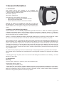
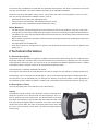
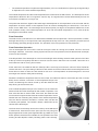
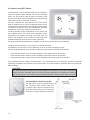
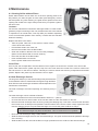
HRU ECO 4
Installer manual
Table of contents
1. General Information
1.1 Introduction
1.2 Warranty and Liability
1.3 Safety
2. Technical Information
2.1 General Description
2.2 Description of Parts
2.3 Dimensional Sketch
2.4 Bypass and Frost Protection
2.5 Specifications
2.6 Capacity Graph
2.7 Sound Data
2.8 Dipswitches
3. Installation regulations
3.1 Installation Requirements
3.2 Check Upon Delivery
3.3 Turning the unit
3.4 Mounting the Unit
3.5 Duct Connections
3.6 Connecting the Condensation Discharge
3.7 Capacity Settings
3.8 Control using RFT Switch
3.9 Hard Wired 3 Position Switch
3.10 Registration of the RFT Operation Switch
4. Maintenance
4.1 Filters
4.2 Heat Exchanger Service
4.3 Maintenance of Ducting
4.4 Motor Module
4.5 Fans
4.6 Control Printed Circuit Board
5. Troubleshooting
5.1 Operation Troubleshooting
5.2 Table of Possible Faults
5.3 Table of Causes
5.4 Table of Solutions
6. Spares
2
3
3
4
5
5
6
6
8
8
9
9
10
10
10
11
11
13
13
14
14
14
15
15
16
16
17
17
18
18
19
19
20
1 General Information
1.1 Introduction
This installer manual was compiled for the installation and
maintenance of the supplied Heatrae Sadia recovery unit HRU ECO
4, which includes the following types:
HRU ECO 4 (House).
HRU ECO 4 (Apartment).
The objectives of this installer manual are to:
• Ensure optimum safety during installation and use.
• Ensure thorough maintenance.
• Provide reference material in the event of a failure.
Although this manual was created with great care, no rights can
be derived from it. These products are in continuous development.
Heatrae Sadia reserve the right to modify this manual without prior
notice.
Compliance with Building Regulations
The 2010 Edition of the U.K Building Regulations Approved Document F1: Means of Ventilation (applicable
in England and Wales) details 4 clearly defined systems of ventilation to dwellings. System 4 - Continuous
mechanical extract with heat recovery (MVHR) is complied with by the new HRU ECO 4 ultra-high efficiency
whole house heat recovery ventilation system.
System 4 - Continuous Mechanical Supply & Extract with Heat Recovery requires a “minimum high rate” in each
wet room to be achieved (kitchens 13 l/s and both utilities and bathrooms 8 l/s (sanitary only 6 l/s).
The “minimum low rate” is calculated by taking the number of bedrooms in the dwelling and applying the l/s
value from Table 5.1b. In addition the rate should be no less than 0.3 l/s per m² of internal floor area (all storeys)
plus for each additional occupant over and above the anticipated two for the first bedroom and one for each
of the others a further 4 l/s must be added to the extract rate. Also, there is an addition of an allowance to be
calculated for air infiltration. The system provides quiet, uninterrupted extract ventilation from the dwelling,
removing warm stale air via all of the “wet” rooms, creating a permanent air path through the property from the
“dry” habitable rooms.
Air, drawn into the property by the fan is routed through an integral high-efficiency synthetic heat exchanger
where warmth from the extracted air is transferred to the incoming fresh air before it is supplied to the habitable
rooms.
In employing this type of system, there is no need to install background ventilators in the dwelling – an ideal
solution to “noisy” sites.
1.2 Introduction
Warranty
The HRU ECO 4 warranty is valid for 2 years after installation date.
The warranty does not apply to:
- Disassembly and assembly costs.
- Faults which are, in the opinion of Heatrae Sadia, caused by incorrect treatment, negligence or an accident.
- Faults that have been caused by repairs or intended repairs by third parties without authorisation from Heatrae
Sadia. If the appliance does not function correctly or develops a fault, contact Heatrae Sadia immediately.
Ensure that only genuine spares are used for any repairs.
3
Liability
The HRU ECO 4 was designed for balanced ventilation systems for both high-rise and low-rise dwellings. Heatrae Sadia is not liable for any other type of application that has not been discussed and approved by them.
Heatrae Sadia is not liable for any damages caused by:
•
•
•
•
Improper use.
Normal wear and tear.
Not following the instructions in this manual concerning safety, operation and/or maintenance.
The use of parts which have not been supplied by Heatrae Sadia or their approved resellers.
1.3 Safety
General Safety
The HRU ECO 4 heat recovery unit has been designed for integration into a ventilation installation.
WARNING
•
•
•
•
•
Do not use this appliance for functions other than those described in the booklet.
After removing the appliance from its packaging, ensure that it is complete and undamaged. If in doubt
contact Heatrae Sadia. Do not leave the packaging within reach of children or the infirm.
Certain fundamental rules must be observed when using any electrical appliance, including a) never touch
appliances with wet or damp hands; b) never touch appliances while barefoot; c) do not allow children to
use the appliance without supervision; d) supervise infirm persons when using the appliance.
Store the appliance out of the reach of children and infirm persons if you decide to disconnect it from the
power supply and no longer use it.
Do not operate the appliance in the presence of inflammable substances or vapours (alcohols, insecticides,
petrol, etc).
CAUTION
The following general instructions are important:
• Follow the safety instructions to prevent fan damage and personal injuries.
• Maintenance instructions must be followed to prevent damage and/or excessive wear and tear.
• The specifications in this manual may not be modified.
• The fans may not be modified.
• The motor module is only suitable for a 230 V 50 Hz a.c system.
• Do not expose the appliance to the weather (rain, sun, etc).
• Do not place objects on top of the appliance.
• Regularly inspect the appliance for visible defects. If any faults are found, contact Heatrae Sadia immediately.
• The appliance must only be installed by a professionally qualified person.
• Ensure that the electrical system to which the appliance is connected complies with applicable standards.
• Use a multi-polar switch with a minimum contact gap of 3 mm to install the appliance.
• The appliance should be switched off at the main switch if:
1. The appliance does not function correctly.
2. Cleaning the outside of the appliance.
3. The appliance is not to be used for any length of time.
• Be careful to avoid damaging the electric circuit.
• Do not use the appliance to control activation of water heaters, room heaters etc, nor should it discharge
into the flues of any such appliances.
• Ensure that the appliance discharges into a single duct (dedicated to this product) which is routed to the
outside.
• The air to be extracted from the dwelling must be clean (i.e. free of grease, soot, chemical and corrosive
agents, explosive or flammable mixtures).
• Keep the appliance intake and outlet grilles free to ensure optimum airflow at all times.
4
To ensure that the installation complies with the applicable CE Directives, the electric connections of the heat
recovery unit HRU ECO 4 should be installed according to the applicable standards.
The device has to be assembled “safe-to-touch”. This means, that under normal operation no-one can come
near any turning parts without a deliberate action, such as:
• Disassembly of the casing with appropriate tools.
• Taking out the heat exchanger after disassembling the casing.
• Removing the motor module after disassembling the casing.
Safety Measures
•
•
•
•
•
The HRU ECO 4 has been designed and constructed such that it is impossible to come into contact with
moving parts or parts under voltage when the system is used in a normal way and without deliberate action.
The HRU ECO 4 meets the legal requirements for electrical devices. The following safety measures should
be taken into account:
Before starting maintenance activities, always electrically discharge the device by isolating the product from
the power supply.
Use appropriate and suitable tools.
Only use the device for an application for which it was designed as indicated in Section 1.2 Warranty and
liability p.3 - 4.
2 Technical information
2.1 General Description
The purpose of the HRU ECO 4 is optimum ventilation of homes with minimal energy loss. Air is extracted from
the kitchen, bathrooms, ensuites, utility rooms and the toilet and, if required, from a storage room. Air is supplied
to the bedrooms and living room. The volumes of air are specified in the Building Regulations Part F1: Means
of Ventilation (ADF). The total volume of air extracted and supplied is equal.
The air flows are completely separated and filtered.
The energy of the discharge air is transferred to the fresh air supply at a high efficiency of approximately 91%.
Condensation can be caused by the discharged air. This must be discharged through the waste water drain.
The HRU ECO 4 can be operated from, for example, the kitchen, using an RFT switch. Correct application of
the ventilation system creates an optimum, healthy and comfortable home climate with minimum energy use.
2.2 Description of Parts
The most important parts of the HRU ECO 4 are the following:
Casing
The patented casing consists of an aluminium casing construction that
clasps the synthetic inner parts around the heat exchanger. This creates an optimum leak-proof construction. The front and back of the heat
exchanger are sealed by a soft synthetic disk with a bayonet catch. The
front of this disk is integrated into the front door. The colour of the casing
construction is RAL 9002, the colour of the front panel is RAL 5014 and
the colour of the front door is RAL 9002. The total unit weighs approximately 25 kg.
5
Compartmentalisation Section
The internal construction for the distribution of the separate air flows is the compartmentalisation section.
This compartmentalisation section consists of four high-quality polypropylene parts and is completely
recyclable. The result of the shape and material of the separate compartments is maximum thermal isolation
and minimum internal air leakage. The cooling of the discharged air flow in the heat exchanger may cause
condensation. The heat exchanger has a catch tray for the condensation which must be connected to the waste
water system.
Heat Exchanger
This counterflow heat exchanger consists of triangular channels. Each channel is, therefore, surrounded by
three channels which flow in the opposite direction. This special construction contributes to an average temperature efficiency of over 91%. The efficiency depends on air volume.
2.3 Dimensional Sketch
2.4 Bypass and Frost Protection Bypass
The heat recovery unit HRU ECO 4 is delivered as standard with a fully integrated bypass valve. This valve is
fully automatic. The bypass ensures that the air from outside is fed around the heat exchanger. It seals the path
to the heat exchanger completely. The return air flow still passes through the heat exchanger.
The fresh outside air is, therefore, not heated but blown directly into the home. This is an advantage on hot summer nights. In these circumstances, the outside air is often cooler than the air within the home. In bypass mode
the returning air is filtered but the intake air is not. The purpose of the bypass is to ventilate the house without
transferring heat. This is only desirable when the following conditions are met:
• The inside temperature is higher than desired.
• The inside temperature is higher than the outside temperature.
6
•
The outside temperature is higher than approximately 19°C for a sufficient time (how long the bypass stays
on depends on the exact outside temperature).
The outside temperature and the inside temperature are measured in the HRU ECO 4. The development of the
temperatures allows the fan to recognise a summer day. The bypass will be closed automatically as soon as
one of these conditions is no longer met.
The power with which the bypass valve discharges heat depends on the temperature of the air inside and the
temperature of the air outside. It also depends on the air volume discharged by the HRU ECO 4. The rule of
thumb for the HRU ECO 4 is to discharge 50 W thermal power per degree of temperature difference at 150
m3/h (medium mode). If the inside temperature is 25°C and the outside temperature is 15°C, 500 W will be
discharged in the medium mode.
Frost Protection
The heat recovery unit HRU ECO 4 is delivered as standard with frost protection. The frost protection consists,
amongst other things, of a unique frost valve integrated at the top of the unit. This protection prevents the unit
from freezing (internally) during the winter. The operation of the frost protection is fully automatic.
Frost Protection Operation
The air discharged from the house is used to heat up the fresh air coming from outside. The air in the heat
exchanger, therefore, cools down. During a period of frost, the frost protection ensures that the heat exchanger
in the unit cannot freeze.
If the temperature of the discharge air in the heat exchanger nears freezing, the device will open the frost valve
at the top of the unit regularly and take in warm air from the area in which the unit is located. This warm air is
mixed with the cold air coming from outside.
At the same time, the intake fan will turn faster (the fan is revved up) to ensure the volume of fresh outside air
remains the same. The pre-heating of the fresh cold outside air ensures that the warm air discharged from the
home does not have to warm the cold outside air too much. The temperature of the discharge air in the heat
exchanger thus remains safely above freezing.
Should the outside air temperature become even lower, the intake fan will turn more slowly (the fan is revved
down) until it reaches a minimum. If the temperature drops even
further, the discharge fan will be revved up and the intake fan will
keep turning at the minimum rate.
If the outside temperature drops to an extreme low, the intake fan
will be turned off but the discharge fan will remain in operation. The
frost valve will also be closed. After some time, the intake fan will
turn at minimum speed and the frost valve will be reopened to check
whether the risk of freezing has passed. If the outside temperature
rises, the above measures are taken in reverse order until the risk
of freezing has passed. The resident “always” determines the air
volume that is discharged.
The frost valve can be easily removed from the top of the HRU ECO
4 without tools. Push the frost valve open (into the unit) using four
fingers against each other (with fingernail side up). Make sure your
thumb presses the black foam outside the unit (between the valve
housing and the adjacent nozzle). Carefully pull the valve housing
7
upwards while sliding it in the horizontal direction of the nozzle. The motor and other bypass parts can now be
inspected. The servomotor can be replaced, if required, by uncoupling the connector and unscrewing the two
Phillips screws.
Important
Make sure nothing is ever placed on top of the frost valve. This would hinder the proper operation of the frost
protection.
2.5 Specifications
Capacity
[m3/h]
Pressure
[Pa]
Cos phi
*
Thermal
efficiency
[%]
Mode 1 Minimum mode
50
10
8
0.05
Mode 1 Low mode
75
20
12
0.1
230
0.07
98
230
0.55
Mode 2 Medium mode
150
40
29
98
0.24
230
0.53
96.2
Mode 2 Medium mode
150
80
Mode 3 High mode
225
100
38
0.31
230
0.53
96.2
74
0.59
230
0.53
Mode 3 High mode
225
94
150
88
0.69
230
0.59
Mode 3 High mode
94
275
100
106
0.83
230
0.56
93
Mode 3 High mode
275
150
126
0.99
230
0.56
93
Mode 3 Maximum mode
325
100
156
1.22
230
0.56
92
Mode 3 Maximum mode
325
150
176
1.36
* Values to be entered in the EPC calculation according to NEN 5128.
230
0.56
92
The thermal efficiency of the HRU ECO 4 has
been determined by TNO at 96.2%, reference
number TNO-MEP 2002KTW/534.
Other technical data
Temperature efficiency
with qual mass flows:
Supply voltage:
Frequency:
2.6 Capacity Graph
8
Power
[W]
Current Voltage
[A]*
[V]*
Weight:
Dimensions:
Duct diameter:
96.2% (measured according
to NEN 5138)
230 V ± 5%
50 Hz
24 kg + 1 kg
848 mm (H)
730 mm (W)
477 mm (D)
150 mm (inner) and
180 mm (outer)
Condensation discharge
diameter:
40 mm (outer)
Degree of protection:
IP31
Filter classification:
EU3
2.7 Sound Data
Radiation
Sound level Lw(A)
m3/h
Pa
Exhaust
63 Hz
[dB]
125 Hz 250 Hz 500 Hz 1000 Hz 2000 Hz 4000 Hz
[dB]
[dB]
[dB]
[dB]
[dB]
[dB]
8000 Hz
[dB]
25
20
<23.5
47.2
30.4
23.3
21.4
13.2
11.5
4.7
75
20
30.5
45.2
34.2
32.1
29.6
24.2
18.1
5.6
9.3
150
80
46.5
46.6
44.9
46.3
44.8
40.9
39.4
25.1
15.4
225
100
53.8
50.0
48.1
52.7
52.2
47.8
47.3
35.7
24.1
225
150
55.0
53.6
48.7
53.0
53.8
48.9
48.7
38.6
29.5
275
100
57.5
58.2
49.6
56.4
55.7
51.5
50.8
41.3
29.4
275
150
58.5
61.8
50.4
56.8
56.7
52.5
51.8
43.4
38.4
325
100
60.5
58.6
50.4
58.9
58.1
54.7
53.7
45.6
33.7
325
150
61.5
54.7
51.8
59.2
59.3
55.6
54.5
47.2
37.0
Total
[dB(A)]
63 Hz
[dB]
Sound level Lw(A)
m3/h
Pa
125 Hz 250 Hz 500 Hz 1000 Hz 2000 Hz 4000 Hz
[dB]
[dB]
[dB]
[dB]
[dB]
[dB]
9.4
8000 Hz
[dB]
25
20
20.5
46.2
19.7
22.6
15.2
10.3
7.1
4.3
75
20
28.5
46.7
28.8
33.0
25.4
22.3
12.1
4.7
8.8
150
80
42.5
45.9
37.3
46.9
40.0
37.0
30.6
15.1
12.5
225
100
49.5
47.0
41.8
53.7
47.6
43.2
37.7
25.3
14.3
225
150
50.5
46.8
43.2
53.6
49.4
44.1
38.9
27.0
14.9
275
100
53.5
46.8
43.6
58.4
50.8
46.9
40.9
30.7
16.8
275
150
54.0
46.8
46.1
58.1
52.1
47.8
42.0
32.5
17.4
325
100
56.5
47.2
44.7
61.4
53.6
49.9
43.8
35.1
19.8
325
150
57.0
48.6
46.5
60.6
54.9
50.6
44.5
36.3
20.6
Total
[dB(A)]
63 Hz
[dB]
Sound level Lw(A)
m3/h
Pa
Inlet
Total
[dB(A)]
125 Hz 250 Hz 500 Hz 1000 Hz 2000 Hz 4000 Hz
[dB]
[dB]
[dB]
[dB]
[dB]
[dB]
9.0
8000 Hz
[dB]
25
20
30.0
33.6
29.4
29.5
29.7
22.7
21.7
7.2
12.0
75
20
40.5
47.3
40.8
40.8
40.2
35.3
28.1
13.4
12.7
150
80
56.5
50.0
51.9
56.7
54.9
51.3
48.9
36.2
22.9
225
100
65.3
50.7
56.0
64.4
65.6
58.6
57.5
47.0
33.6
225
150
66.0
51.4
56.7
64.7
65.5
59.7
59.1
48.9
35.5
275
100
69.5
52.1
57.2
68.0
69.6
62.4
61.1
52.7
39.1
275
150
70.5
53.0
58.0
58.8
70.6
63.3
62.2
54.6
40.5
325
100
73.0
53.2
57.7
70.3
72.9
65.9
64.2
57.2
43.6
325
150
74.0
54.1
58.7
71.3
74.1
67.0
65.0
58.7
45.0
2.8 Dipswitches
OFF
- VKK dipswitch (not for UK market)
Dipswitch must be set OFF.
- AWW dipswitch.
ON
VKK (1)
AWW (2)
9
3 Installation Regulations
3.1 Installation Requirements
The HRU ECO 4 should be installed following the general and local safety and installation regulations and the
instructions in this manual:
• The HRU ECO 4 should be located on a suitable wall.
• The HRU ECO 4 requires 230 V 50 Hz mains voltage. The tolerance for the mains voltage is 5%. If fitted on
the ring main, the unit needs to fitted with a 3 Amp fuse.
• A two pole isolating switch with a minimum contact gap of 3 mm must be fitted.
• The feeder cable is 1.5 m long and the connection is located at the left side of the unit. If the unit is
assembled backwards, this connection is at the right side of the unit.
• The ducts should be of the correct dimensions.
• The ducts to and from the exterior should be thermally insulated and damp proof.
• Insulate all ducts and also the condensate drain, if the unit is mounted outside the thermal envelope of the
building.
• The HRU ECO 4 should be mounted on a wall with a wall mass of at least 200 kg/m².
• The supplied silencer (D = 180 mm, L = 50 cm) should be added to the supply duct to the home to achieve
the optimum comfort level in the home.
• The HRU ECO 4 has a condensation discharge that should be connected to the house waste system.
(Refer to Section 3.6. p.13)
• The HRU ECO 4 has to be mounted vertically and level due to the catch tray.
• The HRU ECO 4 should be accessible for service and maintenance work. Make sure there is 500 mm open
space at the front of the unit. This means that a distance of a metre from the wall should be available at the
location where the unit is to be placed. That space is required to be able to slide the service module, the
heat exchanger and the filters out of the unit. The bottom of the unit and the electrical connections at the
side should also be accessible for service work.
3.2 Check Upon Delivery
Check the unit upon delivery to discover any faults prior to assembly. This ensures the unit can be easily
exchanged without requiring additional work.
•
•
•
Check whether the name plate data and the sticker on the box are correct before removing the packaging.
Take the unit carefully out of the box. The unit can best be placed on the nozzles at the bottom or top. Check
the unit for visible damage.
The condensation coupling and the user manual should be included in the box.
3.3 Turning the Unit
The HRU ECO 4 is delivered as standard with the motor module at the left. The unit can be easily turned
without using tools before it is mounted if this is preferable with regards to the position of the duct system. If the
unit does not require turning, please continue with the instructions in Section 3.4. p.11 If the unit does require
turning, follow the instructions below.
• Remove the filters holders (1).
• Turn the front door (2) with bayonet catch 90 degrees
anticlockwise and remove it.
• Turn the bayonet catch at the rear 90 degrees
anticlockwise as well and remove it.
• Move the front plate (2) with your right hand (without
turning it) to the other side and correctly place the plate by
1
pressing the edge under the black edge of the housing.
This is easiest when the unit is flat on the floor. Make
2
sure the floor surface is level to ensure the aluminium
casing is not damaged.
10
•
•
Place the front door at the new front of the unit. Refer to the picture. Turn the front door 90 degrees clockwise until it is vertical. Make sure that the round foam disk is in place in the hole against the heat exchanger
between the front door and the exchanger.
Place the bayonet catch in the new back in the same way. Make sure that the foam disk between the heat
exchanger and the bayonet catch is in place.
The unit has been turned and is ready for assembly. The front is now the rear and vice versa. The electrical
connections are now located at the right of the unit.
3.4 Mounting the Unit
Frost protection valve
Extract from dwelling
Exhaust to atmosphere
Fresh air intake
from atmosphere
The HRU ECO 4 is delivered as standard Supply to dwelling
with a mounting set. The mounting materials (High-Rise Building)
are to be procured elsewhere. The location
of the drill holes is indicated in the drawing.
The edge of the mounting set corresponds
with the centrelines of the ducts. The notch
at the bottom of the mounting set indicates
Place holder for
user manual
the location of the condensation discharge
(left for the standard unit and right for the
turned unit).
•
•
•
•
Determine the exact location for the
unit, keeping the mounting requirements in mind.
Attach the mounting set to the wall using appropriate mounting material.
Place the unit on the lower supports and
push the unit against the wall at the top
in such a way that the mounting strip fits
into the unit.
Lower the unit until the lower part of the
unit is supported by the mounting set
supports.
Filterholders
Electrical conections
Supply to dwelling
(Low-Rise Building)
Condensation
discharge
Fresh air intake
from atmosphere
Extract from
dwelling
Diagram 1, standard version.
Frost protection valve
Supply to dwelling
(High-Rise Building)
Extract from dwelling
Exhaust to atmosphere
3.5 Duct Connections
The HRU ECO 4 is delivered as standard
with the motor module at the left. Diagram 1
shows the duct connections for the standard
version.
Place holder for
user manual
Filterholders
Diagram 2 shows the duct connections for
the turned version.
All exhaust and supply air connections have
an internal diameter of 150 mm and external
180 mm. The connections can be used to
attach modular rigid ducting and insulated
flexible aluminium ducts and accessories.
Each connection is provided with an illustration that shows the direction and source of
the air.
Electrical conections
Extract from
dwelling
Supply to dwelling
(Low-Rise Building)
Condensation
discharge
Diagram 2, turned version.
11
Standard version.
Turned version.
Suction of Fresh Outside Air
This nozzle is used for the intake of outside air. This duct should be thermally
insulated and damp proof to prevent condensation on the outside of the duct.
Discharge to Outside
This nozzle is used for the discharge of air. This duct should be thermally insulated and damp proof to prevent condensation on the inside and outside of the
duct. If venting to the roof, we recommend using a lead-through for the roof
that does not allow condensation or rain to enter. If this is not the case, the
parts of the duct system between the discharge nozzle and the lead-through
in the roof should be water-tight. The unit discharges any condensed water
through the condensation discharge.
Supply to Home in Low-Rise Building
Heated air is supplied to the home through this nozzle. The connection is at
the bottom for a low-rise building unit. The supply nozzle for a high-rise building unit is not used. The silencer duct should be added to the supply duct to
the home to achieve the optimum comfort level in the home.
12
Supply to Home in High-Rise Building
The connection is at the top for a high-rise building unit. The supply nozzle for
a low-rise building is not used.
Return from Home for Low-Rise and High-Rise Buildings
These nozzles are used for the air sucked from the home. The ducts do not
require thermal insulation, unless the unit is mounted outside the thermal
envelope of the building. These two nozzles are connected internally. The
selection of one of the two nozzles for
the return air connection is; therefore,
open to the installer for both the
low-rise and high-rise buildings. It
is also possible to use both nozzles,
which has a positive influence on the
resistance of the duct system. The red
cap is used to close off the unused
nozzle.
3.6 Connecting the Condensation
Discharge
The condensation discharge piping is located at the bottom of the HRU ECO 4. Connect this properly to prevent
damage to the unit by condensation. The exterior diameter of the glued joint of the supplied condensation
discharge coupling is 40 mm. All other materials are to be procured elsewhere. This condensation discharge
can be mounted to a hose column using a glued joint. A hose with an inner diameter of at least 20 mm should
be mounted. Make sure that the hose is placed sufficiently deep into the air trap (at least 30 mm below water
level). Cut the end of the hose diagonally.
The condensation discharge can also be connected using PVC house waste water material. A provision to be
able to refill the air trap should be added in that case. Pour water into the air trap and check the condensation
discharge for leakage. Make sure that the air trap is not completely glued together to allow for the cleaning of
the air trap.
Also insulate the condensate drain, if the unit is mounted outside the thermal envelope of the building to prevent
freezing.
3.7 Capacity Settings
The standard version of the plastic connection cover of the HRU ECO 4 has two potentiometers for the low
mode and the high mode, respectively. These are used to determine the ventilation capacity for the low mode
and the high mode. The medium mode is set to the arithmetic average of the low mode and the high mode. As
standard, the high mode is set to 225 m³/h.
The ventilation volume may only be increased using the trimmer if and
when the required air volume is not attained when the valves are set and
the valves are already completely open. This ensures that as little energy
as possible is used.
The third potentiometer is a balancing potentiometer for the supply fan.
By adjusting the potentiometer one can accelerate or decelerate the
supply fan relatively to the exhaust fan. This is mainly applied if there is
a difference in resistance between the supply channel and the exhaust
channel. If the potentiometer is in the middle position, the speed of the
supply fan is equal to the speed of the exhaust fan.
13
3.8 Control using RFT Switch
The HRU ECO 4 can be operated using the RFT switches.
These are used to switch between low, medium and high
mode. The low mode is used at night, the medium mode
during the day when there are people at home and the high
mode when cooking, showering or bathing.
The RFT switches are often placed in the wet rooms,
(kitchen, bathroom etc). The RFT operation switch can be
used to operate the ventilation from multiple locations (refer
to Section 3.10 below). Up to 20 wireless RFT operation
switches can be used to operate the HRU ECO 4.
The RFT operation switch (transmitter) can be used to set
the ventilation unit to one of the three ventilation modes
(capacities); low, medium and high. The switch also has
a timer. The ventilation unit is switched to high mode for a
predetermined time when the timer button is pressed.
The timer automatically switches the ventilation unit to low mode after the time has elapsed.
The RTF unit comes with a 5 core cable, Live, Neutral and Earth.
To be fitted on a 3 amp fuse if on the main ring circuit or on the 5 amp lighting circuit.
The time setting depends on the number of times the timer button is pressed consecutively:
•
•
•
Press the timer button once to set the ventilation unit to high mode for 10 minutes.
Press the timer button twice to set the ventilation unit to high mode for 20 minutes.
Press the timer button three times to set the ventilation unit to high mode for 30 minutes.
If the operation switch is used by choosing mode 1, 2 or 3 while the timer is in operation, the timer is switched
off and the ventilation unit operates in the chosen mode. The radio frequency operation does not require additional cabling.
CAUTION
The range of the RFT operation switch (transmitter) is 100 metres in a free field. The distance
at which the RFT operation switch can function properly depends on the obstacles interfering
with the RFT signal, i.e, the walls and floors between the RFT operation switch and the receiver.
3.9 Hard Wired 3 Position Switch
The HRU ECO 4 can be operated using
the 3 position switch HRS-3. Step one
is used at night, step two during the day
when there are people at home and step
three when cooking, showering or bathing.
14
4 Maintenance
4.1 Cleaning Grilles without Filters
Grilles without filters can be taken out of the duct opening (twist to the
left). Before you clean the grille in warm water (with detergent), remove
the foam plastic ring. After cleaning, the grille can be replaced in the duct
opening with a twist to the right. Always make sure you replace a grille in
the same room.
The filters
For the user, maintenance is limited to cleaning the filters. In order to safeguard the proper functioning of the unit, the filters will have to be cleaned
or replaced on an annual basis. This may differ per situation depanding
on the environmental pollution from industry or traffic and also activities
within the dwelling.
Replace the filters in this order:
• Take the power cable out of the socket or switch off the
current at the main switch.
• Pull the filter holders out of the unit.
• Remove the old filter from the filter holder.
• Clean the old filter or take the new one from the packaging
(filters can be cleaned with a vacuum cleaner).
• Place the new filter in the filter holder.
• Push the filters back into the unit.
• Put the power cable back in the socket.
Insect Filter
Once a year, the mosquito filter must be cleaned. The occupant can do this him / herself. First, remove the
power cable. Remove the yellow cap at the top of the unit. Now insert the nozzle of the vacuum cleaner into
the hole and turn on the vacuum cleaner. This way the vacuum cleaner removes any mosquitoes and suchlike
present. Replace the yellow cap and switch the unit on again.
4.2 Heat Exchanger Service
The long-term efficiency of the heat exchanger may decrease due
to the insulation effect of contamination that got through the filters.
How often the heat exchanger should be cleaned depends on the
maintenance of the filters.
The heat exchanger will need inspecting and cleaning every 6
years.
The heat exchanger can be cleaned as follows:
• Remove the filters from the unit as described in Section 4.1. (above).
• Unscrew the two nuts at the bottom of the unit but make sure the nuts remain on the bolt.
• Remove the heat exchanger from the unit by pulling the clamping strip. This action causes friction because
the unit has to be as leak-proof as possible. Hold the bottom of the unit to ensure it stays against the wall.
Use the clamping strip to carry the heat exchanger. Do not use the green surfaces to carry it.
CAUTION
The heat exchanger may leak condensation. This is normal and is not a problem.
•
•
•
Rinse the heat exchanger using a soap solution.
Slide the heat exchanger back into the unit without tilting it. The green surface should be parallel to the edge
of the housing.
Slide the filters into the unit until the filter no longer protrudes from the surface of the heat exchanger.
15
•
•
•
•
•
•
•
Fasten the two nuts on the bottom of the unit.
If the sealing disk is not attached to the front door
it should be placed against the heat exchanger.
Put the front door back by pushing it horizontally
into the hole.
Turn the front 90 degrees clockwise until the front
door is vertically in the unit.
Place the feeder cable in the wall socket.
The HRU ECO 4 is ready for use.
Replacement heat exchangers are available from
Heatrae Sadia.
4.3 Maintenance of Ducting
It is our recommendation that the ducting connected
to the extract terminals (located in kitchens, utilities,
bathrooms and en-suites) needs to be inspected every
3 years and cleaned every 6 years. Cleaning of the
grille and ducting can be carried out with a damp cloth.
4.4 Motor Module
All moving parts, except the bypass and the frost protection, are located in
the motor module. The motor module can be replaced or repaired outside the
unit in case of malfunction. The motor module consists of a hard synthetic
plate. The fans and the control are mounted on this plate. This hard synthetic
plate is jammed in the black synthetic foam housing. Follow these instructions for replacing the motor module:
•
•
•
•
•
Isolate the product from the electrical supply.
Remove the communication cables from the unit connectors.
Remove the filters and the heat exchanger as described in Section 4.2.
p.15.
Disconnect the electric cable from the bypass frost valve motor. This has
to take place near the supply fan.
Slide the motor module from the unit while holding the housing to ensure the unit stays mounted on the wall.
Follow the instructions in reverse order to remount the motor module:
•
•
•
•
•
•
•
•
•
•
•
•
•
16
Slide the motor module into the ventilation unit.
Push the casing a little outwards to make it easier to slide the motor module into the unit. The motor
module will encounter some resistance when it is at approximately 3 cm from the fully inserted position.
Press the motor module a little outwards from the inside of the unit.
Slide the motor module until the edge of the housing is level with the module.
Reconnect the bypass cable and the connector.
Position the heat exchanger.
Fasten the two nuts on the bottom of the unit.
Place the filters.
Place the sealing disk.
Mount the front door.
Connect the communication cables.
Place the feeder cable in the wall socket.
The unit is now ready for use.
4.5 Fans
The unit has two energy-saving direct current motors. The fans have a permanent magnet motor and therefore,
the required energy supply is minimal. The blades are robust and bent backwards. The shape of the blades
ensures the fan is less susceptible to long-term contamination. The maintenance frequency for the cleaning of
the blades is normally once every six years but this depends on the maintenance of the filters.
Follow these instructions to assemble and disassemble the fans:
•
•
•
•
•
•
•
•
•
•
Remove the two screws which secure the printed circuit
board module to the motor module.
Remove the insulation plate.
Turn the printed circuit board module and pull the connector
from the frost protection sensors and the connector from the
bypass. These are the connectors to the cables that are led
through the black foam synthetic housing.
The hard synthetic plate including the fans, power supply and
control can now be separated from the black foam synthetic
housing.
The fans can now be removed.
Remove the cable seal from the hole.
Disconnect the connector from the printed circuit board.
Loosen the four M4 nuts.
Remove the fan including the vibration dampers from the motor plate and pull the cable with the connector
through the hole in the motor plate.
The fan is now ready for cleaning or replacement.
Follow the instructions in reversed order to remount the fans:
•
•
•
•
•
•
Pull the cable with the connector through the corresponding opening in the motor plate.
Put the ventilator in position by pushing the studs of the four vibration dampers through the motor plate.
Add a blocker ring to every vibration damper. This prevents loosening through vibration.
Fasten the four M4 nuts.
Add the cable seal.
Connect the connector to the printed circuit board. Attention: The upper fan should be connected to the
lower connector. The lower fan should be connected to the upper connector. The frost protection does not
function if this is the other way around. Reconnect the frost protection sensors connector and the bypass
connector. Refer to Section 4.5. (above) for instructions on connecting the printed circuit board.
4.6 Control Printed Circuit Board
The control does not require maintenance. An overview of the functions of the critical parts is provided to help
solve the problem in the event of malfunction:
1. Feeder cable connector.
2. Glass fuse T2A/250 V (20 x 5 mm).
3. Potentiometer balance.
4. Potentiometer low speed.
5. Potentiometer high speed.
6. Dipswitch VKK (1) and AWW (2) - VKK not for UK market.
7. Connector I2C.
8. Connector control printed circuit board.
17
7
(2)
(1)
6
8
1
2
3
4
5
5 Troubleshooting
5.1 Troubleshooting Work Method
The following table contains a list of possible problems. Each problem is followed by a number. This is the
number of the possible cause of the problem. This number can be used to find the possible cause in the table
of causes. Each cause is also followed by a number. This is the number of the possible solution. Follow the
instructions specified in the table.
5.2 Table of Possible Problems
No.
1
2
3
4
5
6
7
8
9
18
Possible Problem
Number of Cause
Neither fan functions.
1; 2; 3
Only the intake fan functions.
4
Only the discharge fan functions.
5; 4
The unit is leaking water.
6; 7
The duct is leaking water.
8; 9
The unit is making a noise.
10; 11
The valves are making a noise.
12; 13
The air quality in the home is bad.
13
The unit does not respond to the 3-position mode switch.
14
5.3 Table of Causes
No. Possible Problem
Number of Solution
1
No power supply to the wall socket.
1
2
The supply cable is not fitted correctly to the unit connector.
2
3
The fuse on the printed circuit board is faulty.
3
4
The fan’s connector on the printed circuit board is not fitted correctly.
4; 5
5
The frost protection is active.
6
6
The condensation discharge has not been connected.
7
7
The condensation discharge is clogged.
8
8
The ducts have not been insulated thermally or are not damp proof.
9
9
A roof lead-through has been applied which is not rain-tight, thermally
insulated or damp proof.
10
10
The unit has been mounted on a wall with a mass less than 200 kg/m².
11
11
The unused nozzle has not been capped.
12
12
An sound insulation hose has NOT been mounted.
13
13
The valves have not been synchronised correctly.
14
14
The 3-position mode switch is faulty.
15
5.4 Table of Solutions
No. Possible Solution or Explanation
1
Check whether the wall socket has supply voltage and repair if required. Check the operation of
the unit.
2
Check whether the plug has been fitted correctly to the unit connector. Check the operation of
the unit.
3
Remove the motor module (refer to Section 4.3. p.16). Check the other parts to find the cause of
the
triggering of the fuse. Correct any defects and replace the fuse T2A /250 V (20 x 5 mm). Check
the operation of the unit.
4
Remove the motor module (refer to Section 4.3. p.16). Check whether the fan connector had
been fitted correctly to the printed circuit board. Check the operation of the unit.
5
Remove the motor module (refer to Section 4.3). Check whether the connector of the intake fan
has not been exchanged with the connector of the discharge fan (chapter 4.5. p.17 ). Check the
operation of the unit.
6
Switch the control of the intake fan off in case of very low outside temperature to avoid frost
problems. When the outside temperature rises again, the intake fan will automatically be
switched on. This is not a fault.
7
Moisture may enter the heat exchanger due to differences in air temperature. This is normal.
Connect the condensation discharge.
8
Remove the obstacle in the condensation discharge.
9
Insulate the ducts thermally and make sure they are damp proof.
10
Use a rain-tight, thermally insulated and damp proof roof lead-through.
11
Ensure the unit is mounted on a wall with a mass of at least 200 kg/m².
12
Close off the unused nozzle using a cap.
13
Mount the sound insulation duct.
14
Synchronise the valves using the air balance calculation.
15
Replace the 3-position mode switch.
19
6 Spares
4
2
1
Item No.
1
2
3
4
20
Heatrae Sadia HRU
Part
Fan (1 only)
PCB Set
Sensors (not shown)
Frost Valve
Part No.
95607722
95615088
95607723
95605905
Notes:
21
Notes:
22
23
HEATRAE SADIA HEATING
Hurricane Way, Norwich NR6 6EA
www.heatraesadia.com
SERVICE
0844 8711535
SERVICE FAX
0844 8711528
EMAIL
[email protected]
24
36006182_issue_01