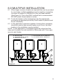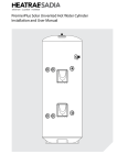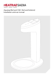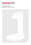
1
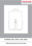
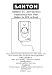
®
Multipoint Instantaneous
®
Fitting Instructions and User Guide
1
INTRODUCTION
Thank you for purchasing a Heatrae Multipoint Instantaneous. The
unvented pressure system water heater is manufactured to the
highest standards and has been designed to meet all the latest
relevant safety specifications.
This Heatrae Multipoint Instantaneous water heater must be
installed (Sections 1-4), commissioned (Section 5) and maintained (Section 7) by a competent person. Please read and understand these
instructions prior to installing your Heatrae Multipoint Instantaneous.
Particular attention should be paid to the section headed important
installation points (Section 1)
This appliance is not intended for use by persons (including children)
with reduced physical, sensory or mental capabilities, or lack of
experience and knowledge, unless they have been given supervision
or instruction concerning the use of the appliance by a person
responsible for their safety. Children should be supervised to ensure
that they do not play with the appliance.
COMPONENT CHECKLIST
Before commencing installation check that all the following
components have been supplied with your Multipoint Instantaneous
water heater.
•
Heater
•
Fixing screws and plugs
•
Pressure relief valve 1MPa (10bar)
•
Tee piece
•
Installation and User Instructions
2
TECHNICAL SPECIFICATIONS
Model numbers
7.0kW - 95 050 424
9.0kW - 95 050 425
12.0kW - 95 050 426
Electrical rating
6.4 - 7.0kW 230 - 240V
8.2 - 9.0 kW 230 - 240V
11.0 - 12.0kW 230 -240V
Rated pressure
Minimum supply pressure
0.1Mpa (1 bar)
Maximum supply pressure
0.7Mpa (7 bar)
Enclosure rated
IP X5
Materials
Backplate, cover - ABS
Element(s) - copper sheathed rod type
Dimensions
Height - 210mm
Width - 160mm
Depth - 104mm
STANDARDS AND APPROVALS
Complies with the requirement of EN 60335-2-35.
British Electro technical Approvals Board (BEAB) approved.
Complies with European Community Directives (CE).
Complies with UK water regulations, kiwa approved.
3
red
Neon
black
Inner
container
green/yellow
red
red
red
red
red
Terminal
block
Pressure
switches
7kW / 9kW / 12kW
N
L
Figure 1 - Wiring Diagram
TEMPERATURE LIMITER 2
FIXING HOLES (3 NOS.)
TEMPERATURE
LIMITER 1
DIFFERENTIAL PRESSURE
SWITCH ASSEMBLY
MAINS CONNECTOR BLOCK
WATER CONTAINER
ASSEMBLY
CABLE GRIP
DRAIN PLUG
7kW / 9kW / 12kW
Figure 2
4
1.0 IMPORTANT INSTALLATION
POINTS
1.1 Products manufactured by Heatrae Sadia are to British and
European Standards.These appliances are safe and without
risk, provided they are installed, used and maintained in good working order in accordance with our instructions and recommendations.
1.2 Please read and understand these instructions before starting work and retain them for later use.
1.3 DO NOT operate the appliance if it is frozen, or suspected of being frozen. See fault finding table.
1.4 These heaters are of the closed outlet type (unvented pressure system) and are suitable for connection to normal cold water mains supplies up to a maximum of 0.7MPa (7bar)
1.5 DO NOT operate the appliance if:
1. Water ceases to flow during use.
2. Water has entered inside the unit because of an incorrectly fitted cover.
3. If the appliance is damaged.
(in all cases turn off mains power)
1.6 ISOLATE the electrical and water supplies before removing the cover.
1.7 ISOLATE the electrical and water supplies BEFORE proceeding with installation or servicing.
1.8 The product is NOT SUITABLE for mounting into steam rooms or steam cubicles.
1.9 The installation must be carried out in accordance with the relevant requirements of: • The appropriate Building Regulations either The Building Regulations, The Building Regulations (Scotland) or Building Regulations (Northern Ireland).
• The Water Fittings Regulations or Water Byelaws in Scotland.
• The IEE Wiring Regulations - BS7671.
CAUTION
1.10It is recommended that persons who may have difficulty
understanding or operating the controls should not be left
unattended whilst using the appliance. Special consideration should be given to young children and persons with reduced physical, sensory, or mental capabilities.
1.11 Only use designated entry points for cable and pipe.
5
PLUMBING
1.12 The plumbing installation must comply with Water Regulations.
1.13 The supply pipe must be flushed to clear debris.
1.14 DO NOT solder pipes or fittings within 300mm once the pipe work
is located in the appliance, as heat transfer can damage components.
1.15 All plumbing connections must be completed and checked for leaks before making the electrical connections.
ELECTRICAL
1.16 Before fitting the appliance, ensure that the consumer unit and any switches are suitable for the additional load. If in doubt, contact your electricity supplier or a qualified electrician.
1.17 The installation must comply with the latest BS 7671
‘Requirements’ for Electrical Installations’ (IEE Wiring Regulations).
1.18 This appliance must be earthed.
1.19A residual current device (rcd), formerly known as an earth leakage circuit breaker (elcb), with a tripping current of 30mA
must be incorporated in the circuit.
2.0 INSTALLATION - WATER SUPPLY
WATER REQUIREMENTS
2.1 The heater must be connected via the tee piece and pressure relief valve to a cold supply having a minimum pressure of 0.1Mpa (1bar) and a maximum of 0.7Mpa (7bar). Both inlet and outlet connections are suitable for 15mm diameter copper pipe. Outlet pipe from unit may reduce to 10mm diameter to improve performance.
2.2 The tee piece and pressure relief valve must be situated where shown and the relief valve discharge port plumbed via an air break (tundish) to a safe, visible place where there is no risk from hot water to persons using the building.
2.3 The discharge pipe must fall continuously from the valve outlets and be unobstructed.
2.4 The provision of a service stop valve in the cold supply pipe will assist in the event of any subsequent servicing or maintenance.
2.5 To obtain optimum performance a flow restrictor (isolating ball valve) must be fitted where shown (see figure 3). This provides the user with the means to govern the flow (and therefore temperature which is dependent upon flow) at the outlet (see under SETTING FLOW RATE).
6
C
A
B
A - OUTLET VALVE
B - FLOW RESTRICTOR
C - MULTIPOINT INSTANTANEOUS
D - PRESSURE RELIEF VALVE
E - SERVICES STOP VALVE
D
E
Figure 3
3.0 INSTALLATION - ELECTRICAL
REQUIREMENTS
ELECTRICAL REQUIREMENTS
3.6 This appliance must be earthed.
3.7 The installation, supply cable and circuit protection must conform to the latest BS7671 ‘Requirements for electrical installations’ (IEE Wiring Regulations).
3.8 The Multipoint Instantaneous heater must only be connected to a 230/240V ac supply.
3.9 Before making any electrical connections within the installation, make sure that no terminal is live. If in doubt, SWITCH OFF the whole installation at the consumer unit or switch fuse (where fitted).
3.10 The Multipoint Instantaneous heater must be connected to its own independent electrical circuit.
3.11 Check that your consumer unit (main fuse box):
1. has a main switch rating of 80A or above.
2. has a spare fuse way which will take the fuse/mcb you need to fit - see Fig. 4. If so, you can wire the Multipoint Instantaneous direct to the spare fuse of your consumer unit via a suitable rated isolated switch- see Fig.4. Note that not all consumer units 7
accept a 35/40/45A sized fuse.
3.12 If point 3.11, 1 and 2 are not achievable, the installation is not
straight forward, since it could involve installing a new consumer unit to serve the whole house or just the Multipoint Instantaneous. You will need to call in your Regional Electricity
Company to check the circuit and make the connections to the meter or service connector block. They will also check the earth bonding of items in the bathroom.
3.13 A residual current device (rcd), formerly known as an earth leakage circuit breaker (elcb), with a tripping current of 30mA must be incorporated in the circuit.
3.14 A double-pole isolating switch (rated at 30A for 7kW, 40A for 9kW, and 50A for 12kW), with a contact separation of at least 3mm in each pole, must be incorporated in the circuit. This must
have a mechanical indicator showing when the contacts are
open. An indicator lamp alone is not sufficient. Only cord operated switches are fitted in bathrooms. Double pole isolating switch:
pull cord or wall mounted in accordance
with IEE regulations
Make cut-out
using sharp knife
RCD (can be part of the
consumer unit)
Multipoint Instantaneous unit
(use rear entry when it is
possible)
Figure 5 - Rear cable entry
80A or 100A main switch
Meter
Consumer unit
Figure 4
8
Meter ‘tails’
4.0 INSTALLATION - MOUNTING
PREPARATION
4.1 Remove the fixing screw which holds the front cover onto the back plate of the Multipoint Instantaneous heater. Carefully remove the cover.
4.2 The unit must be mounted on a flat surface, which covers the full width and length of the back plate. It is important that the wall surface is flat otherwise difficulty may be encountered when fitting the cover.
4.3 DO NOT fit the Multipoint Instantaneous to the wall and tile up to
the case. It must be fitted on to a finished flat and even wall surface. This allows removal for servicing.
CABLE ENTRY
4.4 Cable entry can be from the rear (preferred see Figure 5) or from the bottom. When opting for bottom entry make cut-out to suit cable before fitting back plate to the wall.
4.5 Fix the Multipoint Instantaneous heater loosely to the wall. The wallplugs provided are suitable for most brick walls (use a 6.5mm diameter masonry drill), but if your wall is plasterboard or soft
building block, you should use special wallplugs and an appropriate drill, obtainable from most hardware stores.
PLUMBING
4.6 Decide where to connect to the water mains for your feed to the Multipoint Instantaneous. Ensure that the pipe you have selected is not a gas pipe, a hot water pipe, or from a cold water storage tank.
4.7 Cut the necessary pipe work to length, assemble and offer up to the installation before making any soldered joints. Ensure that the pipe is the correct length, as shortening it can be difficult once joints have been made.
4.8 An isolating stop valve MUST be incorporated to the main water supply to comply with Water Regulations
4.9 Assemble the installation before making any soldered joints to ensure that the pipe is the correct length. DO NOT use jointing compounds on any pipe fittings for the installation.
4.10 Remove the unit before soldering the connections.
4.11 It is essential to flush the pipe in order to clear debris, particles of solder and swarf.
4.12 Turn the water off after flushing using the isolating stop valve.
4.13 Connect the cold water supply pipe to the inlet of the Multipoint Instantaneous, this is a 1/2”BSP connection.
4.14 Fit top and bottom screws and secure the back plate to the wall ensuring that it is level.
9
4.15Connect all other components as per Figure 3.
4.16 Turn the isolating stop valve on slowly and check for leaks in all pipe work, rectify as necessary.
4.17 Turn off the isolating stop valve.
4.18Place the cover onto the back plate.
4.19Secure the cover to back plate using screw provided.
5.0 COMMISSIONING
5.1 Once installed, the heater will operate automatically when the outlet valve is opened. The valve must be opened fully to obtain the set flow/temperature. Reduced flow at the outlet will result in hotter water being delivered.
5.2 On closing the outlet valve the heating element will automatically shut down once flow is reduced to a small amount.
SETTING FLOW RATE
5.3 To set the flow rate, make sure the water and power are turned off. Open the outlet valve fully (see figure 3) and close the flow restrictor. Open the stop valve and open the flow restrictor (allowing all air to be purged). When all air is purged switch the power on, wait for a few seconds while the water is heated and adjust flow restrictor to suit the required temperature. Remember the outlet valve is fully opened at this point so the required temperature may need further adjustment.
5.4 It is important to note when setting the flow rate/temperature that 48°C is the point at which the average person cannot hold his or her hand under a stream of water. Under most circumstances water temperature need not be higher than this and it is
recommended that this temperature is not exceeded.
5.5 These heaters will supply only one outlet at any time and must be controlled by a single outlet valve. DO NOT USE WITH MIXER VALVES.
10
6.0 MULTIPLE INSTALLATION
6.1 When larger volumes of water are required than can be provided by one heater, multiple installations can be made by connecting a number of heaters in PARALLEL of the cold feed manifold (See Figure 6). This is the ONLY method that is recommended. DO NOT plumb these heaters in series.
6.2 To set the heaters in this arrangement use the appropriate procedure as described previously. Each heater in parallel must be set individually.
6.3 In this application restrictors capable of closing flow completely should be used so that as each heater is set in turn, the other heaters in the installation may be isolated.
NOTE - In this application it is advisable especially where low flow
rates exist to plumb the cold manifold in 22mm pipe with 15mm pipe
spurs to each heater.
B - RESTRICTORS
D - PRESSURE RELIEF VALVES
E - SERVICE STOP VALVE
F - COLD WATER SUPPLY MANIFOLD
G - HOT WATER SUPPLY MANIFOLD
D
E
B
F
G
Figure 6
11
7.0 FAULT FINDING
YOUR HEATRAE SADIA MULTIPOINT INTANTANEOUS SHOULD
GIVE TROUBLE FREE OPERATION. HOWEVER SHOULD A FAULT
OCCUR THE TABLE BELOW SHOULD ALLOW MOST FAULTS TO
BE IDENTIFIED. FAULT FINDING SHOULD ONLY BE CARRIED
OUT BY A COMPETENT PERSON.
SYMPTOM
1. Water too hot
2. Water too cold
POSSIBLE CAUSE
A. Water flow too low
A. Electrical power to
the Multipoint heater
is off
B. Water flow too high
C. Element fault
3. Temperature
A. Pressure switch is
varies while
operating,
showering,
normally making a
cycling
"click" as it does so
hot/cold
B. Input pressure is
below 1.0 bar
(14.5psi); flow is
not stable
4. "Power on"
A. Cartridge fuse or
indicator not lit.
miniture circuit
Isolating switch
breaker (mcb) has
"ON" but its
operated in your
neon not lit
fusebox (or
consumer unit) or
switch fuse
B. Residual current
device (rcd) or
(earth leakage
circuit breaker)
has operated
5. Water emerges A. PRV has operated
from pressure
relief valve
6. No water flows
with valve open
A. Water supply turned
off
B. Unit frozen
REMEDY
Increase the flow by turning the water control
Ensure that the electronics to the Multipoint
Instantaneous is switched on and the neon are lit
Reduce the flow by turning the water control
Check for open circuit
Check water pressure/flow
Ensure that your stop cock and servicing
valve are opened fully
Switch off Multipoint Instantaneous and isolating switch.
Renew fuse, reset the mcb. If they operate
a second time, contact a qualified electrician
Follow the same procedure as above. If this
has happened with a "split load" consumer
unit on initial installation, check that the
neutral core of the Multipoint Instantaneous feed cable
is connected to the "protected" neutral bar of the unit
1. Switch off immediately at isolating switch
2. Turn water off at the servicing valve (if fitted)
or stop valve
3. Contact Heatrae Sadia Service Department
Turn on water supply
Turn OFF ELECTRICITY at isolating switch and
contact installer DO NOT USE THE MULTIPOINT
INSTANTANEOUS
For any faults that cannot be identified using the Fault Finding chart
please contact the Heatrae Sadia Service Department, telephone
0844 871 1535, fax 0844 871 1528.
12
8.0 SPARE PARTS
The following comprehensive list of spare parts is available for your Multipoint instantaneous water heater. Please refer to the rating label on the right
hand side of your heater before ordering to ensure the correct spare parts are
obtained.
DO NOT REPLACE WITH PARTS NOT RECOMMENDED BY HEATRAE
SADIA - THIS WILL INVALIDATE YOUR GUARANTEE AND MAY RENDER
THE INSTALLATION DANGEROUS.
Description
Code No
1. Heat Exchanger 7kW.............................................95 606 965
Heat Exchanger 9kW.............................................95 606 966
Heat Exchanger 12kW..........................................95 606 970
2. Temperature limiter 1.............................................95 612 035
3. Temperature limiter 2.............................................95 612 036
4. Pressure differential switch assembly 7kW...........95 613 005
Pressure differential switch assembly 9kW...........95 613 004
Pressure differential switch assembly 12kW.........95 613 006
5. Multipoint instantaneous cover..............................95 614 108
6. Neon assembly......................................................95 615058
7. Inlet boss assembly...............................................95 607 106
8. Outlet boss assembly............................................95 607 109
9. Terminal Block........................................................95 607 249
5
2
3
6
4
1
9
8
7
Figure 7
13
9.0 GUARANTEE
This Multipoint instantaneous water heater is guaranteed for a period
of two years from the date of purchase provided:
1. The unit has been installed in accordance with these instructions
and all necessary inlet, vent and electrical connections have been fitted correctly.
2. Any valves or controls are of Heatrae Sadia recommended type.
3. The unit has not been tampered with and has been regularly
maintained as detailed in the maintenance instructions.
4. The unit has been used only for heating potable water.
The unit is not guaranteed against damage by frost or due to the build
up of scale. Please note that if Heatrae Sadia personnel or agents
are requested to descale a unit, this work will be chargeable.
This guarantee does not affect the statutory rights of the consumer.
The policy of Heatrae Sadia is one of continuous product development
and, as such, we reserve the right to change specifications without
notice.
ENVIRONMENTAL INFORMATION
This product is manufactured from many recyclable materials. At
the end of its useful life it should be disposed of at a Local Authority
Recycling Centre.
14
Notes:
15
Spares Stockists
For the fast and efficient supply of spares please contact the stockists
listed below.
Electric Water Heating Co. 2 Horsecroft Place, Pinnacles
Harlow, Essex, CM19 5BT
Tel: 0845 0553811
E-Mail: [email protected]
SPD
Units 9 & 10 Hexagon Business Centre
Springfield Road, Hayes
Middlesex, UB40 0TY
Tel: 020 8606 3567
Parts Center
Tel: 0845 270 9801
www.partscenter.co.uk
Newey & Eyre
Specialist Products Division
Please contact your local branch
UK Spares Ltd.
Tower Lane, Warmley
Bristol, BS30 8XT
Tel: 0117 961 6670
William Wilson Ltd.
Unit 3A, 780 South Street
Whiteinch, Glasgow, G14 OSY
Tel: 0141 434 1530
®
Heatrae Sadia Heating
Hurricane Way Norwich NR6 6EA
Sales: Sales Fax:
Service: Service Fax:
Service Email:
0844 335 6394
0844 871 1543
0844 871 1535
0844 871 1528 heatraesadiaservice@
heateam.co.uk
www.heatraesadia.com
16
© 2009
36 00 6037
Issue 3