1
Measurement Excellence™
BERTEC CORPORATION
!!!!!!!!!!!!!!!!!!!!!!!!!!!!!!!!!!!!!!!!
Force Plate
User Manual
Copyright © 2005 BERTEC Corporation. All rights reserved. Information in this document
is subject to change without notice. No part of this document may be reproduced or
transmitted in any form or by any means, electronic or mechanical, for any purpose,
without express written permission of BERTEC Corporation or its licensees.
"Measurement Excellence", BERTEC Corporation, and their logos are trademarks of
BERTEC Corporation
Other trademarks are the property of their respective owners.
Bertec’s Authorized Representative in the European Community Regarding CE:
MIE Medical Research Ltd.
6 Wortley Moor Road, Leeds LS124 JF, United Kingdom
Phone:44-113-279 3710
Fax: 44-113-231 0820
Printed in the United States of America.
Limited warranty
LIMITED WARRANTY. Except with respect to any BERTEC Corporation (BERTEC) products sold by or manufactured by
any entity other than BERTEC, its authorized distributors, or suppliers, which are provided "as is", without warranty of
any kind, BERTEC warrants that (a) the BERTEC hardware product is free of all defects in workmanship and material for a
period of seven (7) years from receipt by the end-user or date of installation if such installation is performed by a
representative of BERTEC; (b) the media that BERTEC software is delivered upon are free from defects in workmanship
and material and will perform substantially in accordance with the accompanying written materials for a period of seven
(7) years; and (c) BERTEC support engineers will make commercially reasonable efforts to solve any problem issues as
they arise. Some states and jurisdictions do not allow limitations on duration of an implied warranty, so the above
limitation may not apply to you. To the extent allowed by applicable law, implied warranties on both the BERTEC
hardware product and the BERTEC software product are limited to seven (7) years.
CUSTOMERS REMEDIES. BERTEC's and its distributors' entire liability and the customer's exclusive remedy shall be, at
BERTEC's option, to either repair or replace all BERTEC hardware and/or software products that do not meet BERTEC's
Limited Warranty and are returned to BERTEC. Cost of delivery of the BERTEC product under warranty, to and from
BERTEC, will be the responsibility of BERTEC for the first year of the warranty period. Thereafter, all costs associated with
transport of the BERTEC product shall be the responsibility of the customer. This Limited Warranty is void if failure of the
BERTEC hardware and/or software products has resulted from improper installation by the customer (in contravention of
proper installation instructions as detailed in the user's manual included with the BERTEC product), unauthorized
modifications, misuse or abuse of the BERTEC product by the customer, and/or failure by the customer to properly
maintain the BERTEC product. Any replacement BERTEC product will be warranted for the remainder of the original
warranty period.
NO OTHER WARRANTIES. TO THE MAXIMUM EXTENT PERMITTED BY APPLICABLE LAW, BERTEC AND ITS
DISTRIBUTORS DISCLAIM ALL OTHER WARRANTIES AND CONDITIONS, EITHER EXPRESS OR IMPLIED,
INCLUDING, BUT NOT LIMITED TO, IMPLIED WARRANTIES OF MERCHANTABILITY, FITNESS FOR
PARTICULAR PURPOSE, TITLE AND NON-INFRINGEMENT, WITH REGARD TO THE BERTEC PRODUCT OR THE
PROVISION OR FAILURE TO PROVIDE SUPPORT SERVICES. THIS LIMITED WARRANTY GIVES YOU SPECIFIC
LEGAL RIGHTS. YOU MAY HAVE OTHER LEGAL RIGHTS NOT MENTIONED IN THIS WARRANTY. THESE RIGHTS
MAY VARY IN EACH STATE OR JURISDICTION.
LIMITATION OF LIABILITY. TO THE MAXIMUM EXTENT PERMITTED BY APPLICABLE LAW, IN NO EVENT SHALL
BERTEC (INCLUDING ANY OF BERTEC'S SUBSIDIARIES OR PARENT COMPANIES, SUPPLIERS, DISTRIBUTORS,
RETAILERS, OR MANUFACTURERS) BE LIABLE FOR ANY SPECIAL, INCIDENTAL, INDIRECT, OR
CONSEQUENTIAL DAMAGES WHATSOEVER (INCLUDING, WITHOUT LIMITATION, DAMAGES FOR LOST
BUSINESS PROFIT, BUSINESS INTERRUPTION, LOSS OF BUSINESS INFORMATION, OR ANY OTHER
PECUNIARY LOSS) ARISING OUT OF THE USE OF OR INABILITY TO USE THE BERTEC PRODUCT OR THE
PROVISION OR FAILURE TO PROVIDE SUPPORT SERVICES, EVEN IF BERTEC OR ITS AFFILIATES HAVE BEEN
ADVISED OF THE POSSIBILITY OF SUCH DAMAGES. THE TOTAL LIABILITY OF BERTEC AND/OR ITS
AFFILIATES FOR ANY LOSS, DAMAGE OR CLAIM, WHETHER IN CONTRACT, TORT (INCLUDING ACTIVE OR
PASSIVE NEGLIGENCE OR STRICT LIABILITY) OR OTHERWISE, ARISING OUT OF, CONNECTED WITH, OR
RESULTING FROM THE PERFORMANCE OR BREACH OF ANY PURCHASE ORDER OR CONTRACT OF SALE
ACCEPTED OR EXECUTED BY BERTEC AND/OR ITS AFFILIATES, OR FROM THE DESIGN, MANUFACTURE, SALE,
DELIVERY, RESALE, INSPECTION, ASSEMBLY, TESTING, REPAIR, REPLACEMENT, OPERATION, MAINTENANCE
OR USE OF ANY BERTEC PRODUCT OR ACCESSORY OR FROM THE PERFORMANCE OF ANY SERVICE SHALL
NOT, IN ANY EVENT, EXCEED THE PRICE ALLOCABLE TO THE PRODUCT OR SERVICE WHICH GIVES RISE TO
THE CLAIM, LOSS OR DAMAGE. PROVIDED FURTHER, THAT THE END-USER ASSUMES ALL RISK ASSOCIATED
WITH THE USE OR MISUSE OF THE BERTEC PRODUCT, ACCESSORY OR SERVICE IN CONTRAVENTION OF ANY
DIRECTIONS OR WARNINGS PROVIDED IN BERTEC INSTRUCTIONAL LITERATURE OR GIVEN VERBALLY BY
AN AUTHORIZED BERTEC REPRESENTATIVE, OR THAT SHOULD BE REASONABLE BY COMMERCIALLY
ACCEPTABLE STANDARDS. THE PARTIES (BERTEC, BERTEC'S AFFILIATES, AND THE CUSTOMER OR
END-USER) EXPRESSLY AGREE THAT THE LIMITATIONS ON INCIDENTAL, CONSEQUENTIAL, SPECIAL OR
INDIRECT DAMAGES SET FORTH HEREIN ARE AGREED ALLOCATIONS OF RISK CONSTITUTING IN PART THE
CONSIDERATION FOR THE SALE OF ANY BERTEC PRODUCT, ACCESSORY, OR SERVICE, AND THAT SUCH
LIMITATIONS SHALL SURVIVE THE DETERMINATION OF ANY COURT OF COMPETENT JURISDICTION THAT
ANY REMEDY PROVIDED HEREIN OR AVAILABLE AT LAW FAILS OF ITS ESSENTIAL PURPOSE. BECAUSE SOME
STATES AND JURISDICTIONS DO NOT ALLOW THE EXCLUSION OR LIMITATION OF LIABILITY, THE ABOVE
LIMITATION MAY NOT APPLY TO YOU.
HIGH RISK ACTIVITIES. THE SOFTWARE AND/OR HARDWARE SUPPLIED BY BERTEC IS NOT
FAULT-TOLERANT AND IS NOT DESIGNED, MANUFACTURED OR INTENDED FOR USE OR RESALE AS ON-LINE
CONTROL OR EQUIPMENT IN HAZARDOUS ENVIRONMENTS REQUIRING FAIL-SAFE PERFORMANCE IN WHICH
THE FAILURE OF SOFTWARE AND/OR HARDWARE COULD LEAD DIRECTLY TO DEATH, PERSONAL INJURY, OR
SEVERE PHYSICAL OR ENVIRONMENTAL DAMAGE ("HIGH RISK ACTIVITY"). BERTEC AND ITS SUPPLIERS
SPECIFICALLY DISCLAIM ANY EXPRESS OR IMPLIED WARRANTIES OF FITNESS FOR HIGH RISK ACTIVITIES.
Contents
1
Introduction
1.1. Overview........................................................................ 1
1.2. Customer Support .......................................................... 2
2
Installation
2.1. Mounting the Force Plate ............................................... 3
Without a Mounting Plate .................................................................................... 4
Using a Mounting Plate ....................................................................................... 4
2.2. Cables and Amplifier Connections .................................. 7
3
Data Acquisition and Load Calculations
3.1. Overview........................................................................ 9
3.2. Analog Data Acquisition ................................................. 9
Auto Zero ........................................................................................................10
Calculating Load Values .....................................................................................11
Calculation of Point of Application for the Force and Couple ......................................12
Example 1: Load Computation ............................................................................13
i
Change of Coordinate System............................................................................. 14
Example 2: Change of Reference System.............................................................. 15
3.3. Digital Data Acquisition ................................................ 17
4
Digital Data Acquisition Software
4.1. Overview ...................................................................... 19
4.2. Software Installation ................................................... 20
4.3. Using the Software....................................................... 22
File Name........................................................................................................ 22
Data Acquisition Interval.................................................................................... 23
Software Zero .................................................................................................. 23
Applying a Digital Filter...................................................................................... 24
Selecting Data to Be Saved ................................................................................ 24
The Status Field ............................................................................................... 24
Data Collection................................................................................................. 25
5
Technical Specifications
5.1. Overview ...................................................................... 27
5.2. Force Plates.................................................................. 28
Rated Load ...................................................................................................... 29
Natural Frequency ............................................................................................ 29
Anchor Locations .............................................................................................. 30
5.3. Amplifiers and Signal Converters ................................. 31
AM6500 Digital Signal Converter ......................................................................... 31
AM65XX Series Analog, Fixed Gain Amplifier.......................................................... 32
AM6800 Dual Output, Adjustable Gain Amplifier..................................................... 34
General Specifications ....................................................................................... 35
ii
Introduction
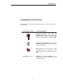
Typographical Conventions
For convenience, the following formatting conventions are used throughout
this document.
Formatting Convention
Type of information
Important messages. They state the
fundamental things to keep in mind while
using the force plates, including safety
notices. The related text is printed in bold.
Step-by-step procedures. The procedure
is identified by its title written in bold italic
next to this symbol.
Tip messages. They state some useful
information about the versatility of the
force plates. The related text is printed in
bold.
Bold Italic font type
iii
Reference to other sections of the
manual where the mentioned topic is
described in detail.
Introduction
1
Introduction
1.1. Overview
Bertec’s product line of force plates have been specifically designed for
gait, balance, sports and other static and dynamic analyses. Through the
use of strain gauge technology, innovative design, and quality
manufacturing, Bertec’s force plates are well suited for both static and
dynamic applications. Each force plate consists of a number of strain
gauged load transducer and a built-in digital pre-amplifier for signal
conditioning. Bertec force plates come in a variety of sizes and associated
load ranges to suit different application needs. The 4550, 4060 and 4080
series plates have been designed specifically for the demands of clinical
and research gait analysis, whereas 6090, 9090 and 6012 series force
plates are well suited for the rigors of sports and other dynamic
biomechanics, ergonomics and industrial research. The rugged honeycomb
technology used for the production of the tops and bases ensure enhanced
dynamic measurement characteristics while keeping the overall weight to
a minimum. All of the models can be portable in that they do not require
separate mounting plates, and can be moved from one location to another.
Smaller models, like 4550 and 4060, also have non-portable versions to be
used with a mounting plate. Years of experience in force plate design
enables Bertec to customize all models to suit customers’ requirements.
Most of the models, for example, can be retrofitted to be waterproof or the
sizes of standard models can be modified for specific applications.
Bertec force plates are six-component load transducers, which measure
the three orthogonal components of the resultant force acting on the plate,
and the three components of the resultant moment in the same orthogonal
coordinate system. The point of application of the force and the couple
acting on the plate can be readily calculated from the measured force and
moment components.
Bertec force plates use a state-of-the-art 16-bit digital technology for
signal acquisition and conditioning. This new technology makes the use of
calibration matrices obsolete, since each plate comes with the calibration
matrix already digitally stored on it. External amplifiers to be used with
force plates provide the user with three signal output alternatives: digital,
analog or dual digital/analog outputs. The digital signal output can be
directly plugged into the standard USB port of the personal computers
without the requirement of an additional PC card for analog-to-digital
(A/D) signal conversion. This plug-and-play technology allows a simpler
Force Plate User Manual – Bertec Corporation ! Page 1
Introduction
installation procedure in a minimum amount of time. The digital data
acquisition software, provided with the force plates as a standard item,
enables the user to collect data quickly without the need of additional
custom designed software. Upon request, software libraries and device
drivers are available from Bertec so that the user can write his/her own
digital data acquisition software.
The analog output of the force plates can be fed into an A/D board so that
data can be collected using conventional techniques. Depending on
application, signal amplification can be performed for analog output using
external amplifiers. External amplifiers are either fixed gain (factory set
according to customer requirements) or adjustable gain (seven adjustable
gains). These amplifiers enable the user to establish a trade-off between
the measurement range and resolution of the force plates.
The wide variety of force plates in Bertec’s product line can be used with
any type of motion analysis system ranging from camera-based systems
using passive markers to systems with active markers or magnetic
sensors. For example, the 4060-NC model is a non-conductive plate
specifically designed to be used in environments requiring measurement of
magnetic fields.
1.2. Customer Support
For any questions or inquiries regarding Bertec products you can contact:
Bertec Corporation
6171 Huntley Road, Suite J
Columbus, OH 43229, U.S.A.
Phone: +1 614 430-5421
Fax: +1 614 430-5425
e-mails: [email protected], [email protected]
www.bertec.com
Suggestions or comments about Bertec products are always welcomed.
Page 2
!
Force Plate User Manual – Bertec Corporation
Installation
2
Installation
2.1. Mounting the Force Plate
All Bertec force plates are pre-assembled in the factory. Therefore, they
are ready to be installed by mounting them to the floor, and by connecting
all the cables.
Do not attempt to disassemble the force plate, damage can occur
to the transducer components or electronics. The Limited
Warranty is void if the force plate or any of the accessories are
disassembled without the authorization of Bertec.
To obtain a high quality measurement from Bertec force plates they should
be installed in a way that is suitable for the type of measurement to be
performed. First of all, the floor and structure underneath should be
prepared to be as rigid as possible in order to minimize any vibrations.
Bertec force plates are very sensitive devices. Therefore, they will pick up
any vibration coming from the support structure. A second consideration is
the flatness of the mounting surface. Bertec force plates are designed to
work accurately on uneven surfaces. However, overstraining them during
installation or while using, might introduce errors into the measurements.
Fixing the force plate to a surface is optional. If the application for the
force plate involves high horizontal forces, which might cause the plate to
slide, then it is strongly suggested that the plate be anchored using the
mounting locations provided on the feet. Depending on the model used, an
additional mounting plate might be necessary to fix the force plate to the
floor.
For effective use the top surface of the force plate should be at the same
level as the rest of the floor. For this purpose, a pit can be made in which
the plate is mounted. Alternatively, a raised walkway can be used with the
top surface of the walkway at the same height as the top of the force
plate. No matter what methodology is used, remember to leave room for
the output cable and make sure that the force plate does not touch any
surrounding structure as this might result in measurement errors. A gap of
1-2 mm (0.04”-0.08”) between the force plate and surrounding floor will
be appropriate. The following practical considerations will be helpful during
installation. If you need additional assistance, please contact Bertec
Corporation (see 1.2. Customer Support):
Force Plate User Manual – Bertec Corporation ! Page 3
Installation
•
The pit should be deep enough to accommodate the height of
both the force plate and mounting plate. Leave an additional
⅛”-¼” space for leveling tolerances.
•
Size of the pit should be large enough to take future
expansion plans into account, such as adding more force
plates or other equipment.
•
Allow at least 8” (20 cm) free space around the force plate so
that the output cable is not crammed, and the wrench to
tighten the mounting bolts can be operated easily.
•
Incorporate a conduit into the construction plan so that the
output cable will run under the floor. Make the conduit large
enough for the cable connector to pass through. The
minimum diameter for a straight conduit should be 1¾” (45
mm). If there are bends and corners in the conduit, then the
recommended diameter is 3 inches (75 mm).
Without a Mounting Plate
Bertec force plates may be used on any type of surface. When used on a
hard, non-flat surface shimming is required to prevent rocking of the plate
(plain paper works fine for shimming small gaps up to 1/32”). When
mounting to a concrete surface, Bertec recommends using threaded
anchors permanently affixed to the concrete floor. The standard bolts to be
used with force plates are of the size ⅜” – 16 UNC (or M8 – 1.25 for
European customers). For the exact locations of the anchor points for
different force plate models, please refer to section 5.2 Force Plates.
Finally, the area where the plate is going to be mounted should be clean.
Caution should be taken, however, when using unfixed force
plates. Large shear forces may cause an unattached plate to
move on the surface, which can be dangerous for both the
subject and any by-standers. Bertec recommends avoiding the
use of unfixed plates in these situations.
If you are not sure about the flatness of the mounting surface,
then tighten the anchoring bolts as little as possible to avoid
bending the base of the force plate. Make sure that the only
contact is between the feet and mounting surface, and the entire
surface below the feet is properly shimmed.
Using a Mounting Plate
Standard Mounting Plates are ¾” (19 mm) thick and have the same
dimensions as the force plate. The Mounting Plates come with pre-tapped
holes that mach the anchor locations on the feet of the force plate, along
with leveling hardware. Typically, the Mounting Plate is rigidly affixed to
the floor with a high strength epoxy. Then, the plate is mounted onto the
Page 4
!
Force Plate User Manual – Bertec Corporation
Installation
mounting plate via four hexagonal cap screws of size ⅜” – 16 UNC (or M8
– 1.25). The following installation hardware is provided with the Mounting
Plate:
•
•
•
•
•
•
High Strength Epoxy – to glue the Mounting Plate
Trowel and Putty Knife – to spread the epoxy on the floor
Water Level – to adjust the levelness of the force plate
Hexagonal Allen Key – to adjust the set screws on the Mounting Plate
Eye Bolts – to lift the Mounting Plate
Hexagonal Cap Screws – to attach force plate to the Mounting Plate
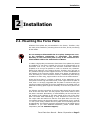
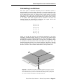
Please read all instructions before installing the Mounting Plate:
Mounting Plate
Installation
!
Place mounting plate on concrete floor in desired location.
Ensure that the setscrews on the Mounting Plate are not
touching the floor at this point (depending on the size of the
Mounting Plate there may be four (4) or more set screws). The
provided eyebolts may be used in the force plate mounting
locations to make lifting of the Mounting Plate easier.
Figure 2.1 – The eyebolts can be used to lift the plate. The
adjustable setscrews are used to level the Mounting Plate
!
Assemble the force plate to Mounting Plate using outer corner
holes with provided bolts (⅜”–16 UNC or M8–1.25) and
washers.
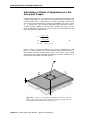
!
Level force plate using the outer accessible setscrews (the ones
closer to the edge of Mounting Plate). The water scale provided
can be used on top of the force plate if necessary. Make sure
that Mounting Plate is lifted from the floor at least 1/16–1/8
inches (2–3 mm) to allow room for the glue. If the force plate
Force Plate User Manual – Bertec Corporation ! Page 5
Installation
is to be mounted in a pit, which does not provide easy access
to the setscrews, the Mounting Plate can be leveled first.
However, make sure that the top of the force plate is flush with
the surrounding floor before proceeding further.
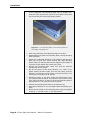
Figure 2.2 – The Mounting Plate can be leveled while the
force plate is mounted on it.
Page 6
!
!
Mark outer perimeter of the Mounting Plate on the floor.
!
Disassemble force plate from Mounting Plate, leaving Mounting
Plate in position.
!
Adjust any unadjusted setscrews in the middle of the Mounting
Plate just to touch floor. When working with large Mounting
Plates make sure that the plate has not sagged in the middle. If
necessary further adjust with central set screws.
!
Remove the Mounting Plate. Make sure that the setscrew
adjustments do not change.
!
Mix the two parts of the epoxy adhesive (1:1 ratio) in the
plastic bucket provided. Make sure that the epoxy and the
hardener is thoroughly mixed (about 5 minutes by hand). The
working life of the epoxy is 30 minutes.
!
Spread the epoxy on the floor, within the marked area, using
the notched trowel provided. The notches of the trowel will help
form “hills and valleys” of epoxy so that when Mounting Plate is
placed back on it, the epoxy has room to spread.
!
Relocate the Mounting Plate back to the marked area.
!
Allow epoxy adhesive to cure overnight before assembling force
plate.
!
Mount the force plate to the Mounting Plate using the supplied
screws (⅜” – 16 UNC or M8 – 1.25) and washers.
Force Plate User Manual – Bertec Corporation
Installation
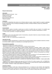
2.2. Cables and Amplifier Connections
After the force plate is mounted onto the floor, the next step in the
installation is making the cable connections with external amplifiers and
the computer. The standard output of Bertec force plates is an 8-pin male
round receptacle. The standard output cable is 10 m (33’) long, has an 8pin round female connector at the force plate end, and a 9-pin male D-Sub
connector at the other end. The first step is to connect the force plate
output cable to the force plate:
Connecting Force
Plate Cable
!
Identify the 8-pin female round connector on the force plate
output cable.
!
Match the keys of the plug and receptacle.
!
Push in the connector and rotate (about ¼ turn) clockwise until
the two fully engage and lock.
Depending on the configuration of the system, the 9-pin male connector
plugs into an external amplifier or signal converter. Analog output from
Bertec signal conditioning amplifiers is a standard 15-pin female D-Sub
connector. The output of the external amplifier connects to the computer
used for data acquisition. For analog outputs an additional A/D signal
conversion card on the PC is necessary. Digital output of the amplifiers
plugs directly into the USB port of the computer using the USB cable
provided with the system. Pin configuration for the analog output is given
in Chapter 5: Technical Specifications.
Additional analog output cables to connect amplifiers to A/D boards are
available from Bertec Corporation. One end of these cables is always a 15pin male D-Sub connector, which plugs into the amplifier. The other end is
manufactured depending on specific customer order (e.g. BNC, bare wire
leads, etc.).
Whatever system configuration you use, the electrical network,
that is used to supply power to the data acquisition systems and
force plates, should be properly grounded. Poor grounding is a
common source of signal noise in electronic systems. Although,
all Bertec force plates and amplifiers carry the CE mark of the
European Union to ensure high signal quality, improper grounding
and external power sources might degrade signal characteristics.
Force plate cables can be a hazard for tripping. It is
recommended that these cables be routed to prevent tripping.
Alternatively, use masking tape, or some other non-permanent
means to hold the cables to the floor.
Force Plate User Manual – Bertec Corporation ! Page 7
Data Acquisition and Load Calculations
3
Data Acquisition and
Load Calculations
3.1. Overview
All Bertec products use a novel 16-bit digital technology for signal
acquisition and conditioning. The output signal of the load transducers are
already digitized and conditioned in the force plate by using state-of-theart electronics developed by Bertec Corporation. With this new technology
the output signal has a very high signal-to-noise ratio, which means
increased sensitivity and accuracy for the force plates. In addition, the
digital technology makes the use of calibration matrices obsolete, since
each plate comes with the calibration matrix already digitally stored on it.
Depending on the configuration, the system provides the user with a
digital, analog or dual digital/analog output.
The digital output of the system is always in the form of calibrated data in
their respective units selected by the user (N and N·m, or lb and lb·in).
The analog output requires an additional scaling depending on the external
amplification used in data acquisition.
3.2. Analog Data Acquisition
The output of the force plate is in the form of a 16-bit digital signal.
External digital-to-analog (D/A) converters are used in order to obtain
analog output to be used in conventional data acquisition systems. The
D/A converters are also analog amplifiers with either a fixed (65XX series)
or adjustable gain (6800 series) setting (for a detailed description of
amplifiers please refer to 5.3 Amplifiers). The pin configuration for the
15-pin analog output is given in Chapter 5. Technical Specifications.
Force Plate User Manual – Bertec Corporation ! Page 9
Data Acquisition and Load Calculations
Before starting to collect data, make sure that the cables from the
force plate to the amplifier, and from the amplifier to the PC is
properly connected. Power to the amplifier should be connected,
and the amplifier should be turned on (in 6800 series only).
The force transducer system reaches thermal stability in about 5
minutes. Therefore, always allow the equipment to warm up at
least for 5 minutes before collecting data.
Auto Zero
All analog amplifiers are equipped with an “Auto Zero” button. This button
allows zeroing offset loads up to full scale. This functionality can be used
to remove tare weight of equipment such as a chair or a step, placed onto
the force plate as part of the measurement protocol. When the amplifier is
first turned on, of the two green lights next to the auto zero button, only
the bottom one will be on, confirming that the amplifier is powered. This
indicates that zero has not been set yet. Simply press and release the auto
zero button in order to zero the bridges on the amplifier. When zero is set,
both lights next to the auto zero switch will be on.
For the variable gain 6800 series amplifiers, the auto zero switch is next to
the power switch on the front panel. For the fixed gain amplifiers (65XX
series) it is located next to the 15-pin output connector.
Note that auto zeroing sets all channels to near zero. True zeroing
should be done by software at the time of data collection, by
subtracting a baseline reading from the collected data.
The analog data acquisition procedure can be summarized as follows:
Analog Data
Acquisition
Page 10
!
!
Check all the cables, and make sure that they are properly
connected.
!
Turn on the amplifiers, and allow the system to warm up at
least for 5 minutes.
!
For the 6800 series variable gain amplifiers, set a proper gain
value for the data channels using the gain switch on the front
panel of the amplifier.
!
Press the auto zero button in order to remove any offset load
on the force plate.
!
Collect analog data using software. Remember to remove a
baseline reading from the signals using software in order to set
the signal mean values to true zero.
Force Plate User Manual – Bertec Corporation
Data Acquisition and Load Calculations
Calculating Load Values
Each force plate is calibrated individually and the calibration matrix is
stored digitally in the force plate. Therefore, the analog output from the
amplifier provides full-scale calibrated output (±5 V) per rated load range
of the attached force plate. The voltage output of each channel is a scaled
form of the load in the units of N and N·m for the forces and moments
respectively. The scale factor for each channel for a gain of unity is given
in the product data sheet supplied with the transducer. The force and
moment values are calculated by multiplying the signal values with
corresponding scale factors, as given in Eqn. 1:
Fx = C1 · S1
Fy = C2 · S2
Fz = C3 · S3
(1)
Mx = C4 · S4
My = C5 · S5
Mz = C6 · S6
where, F’s and M’s are the force and moment components in the force
transducer coordinate system (Figure 3.1), and S’s are the output signals
corresponding to the channels indicated by their subscripts, in volts,
divided by the respective channel gain. The origin of the coordinate system
is centered on the top surface of the force plate (see Figure 3.1). The
standard coordinate system is such that the positive y-direction is opposite
to the connector end; x-axis is to the left when looking in the y-axis
direction; and the z-axis is defined downwards by the right hand rule.
Figure 3.1– Standard force plate coordinate system: the origin is on the
top surface, and at the center of the plate. Positive y-direction is opposite
to the connector end; x-axis is to the left when looking in the y-axis; and
the z-axis is defined downwards by the right hand rule.
Force Plate User Manual – Bertec Corporation ! Page 11
Data Acquisition and Load Calculations
Calculation of Point of Application for the
Force and Couple
A load system acting on a force plate can be completely described by the
six load components (i.e. the three force and three moment components)
calculated from Eqn. 1. Alternatively, the same information can be given
as the three force components, the point of application of the force vector
(xp, yp in Figure 3.2), and a couple (sometimes also referred as “torque “
or “free moment”) acting on the force plate. Referring to Figure 3.2, the
point of application of the force, and the couple are calculated from the
force and moment components as:
xp =
yp =
−h ⋅ Fx − M y
Fz
− h ⋅ Fy + M x
Fz
(2)
Tz = M z − x p ⋅ Fy + y p ⋅ Fx
where, xp and yp are the coordinates of the point of application for the
force (i.e. center of pressure); h is the thickness, above the top surface, of
any material covering the force plate (Figure 3.2); and Tz is the couple
acting on the force plate. Note that the thickness h, shown in Figure 3.2, is
to be entered as a positive number in Eqn. 2.
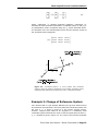
Figure 3.2 – A force F, and the point of application of the force. The force
plate is covered with a layer of floor covering, which has a thickness h. The
thickness h is entered as positive number in Eqn. 2.
Page 12
!
Force Plate User Manual – Bertec Corporation
Data Acquisition and Load Calculations
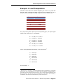
Example 1: Load Computation
Consider a case where the external amplifier gain is set to 10 (note that
the gain value is always the same for all of the six channels). If, at an
instant in time, the amplifier voltage outputs for the six channels are:
CHANNEL
OUTPUT, V
1
-1.450
2
2.235
3
4.765
4
3.095
5
-0.575
6
-1.016
Then, by dividing each output by the corresponding gain, the output signal
values to be used in Eqn. 1 are obtained:
S1 = -1.450/10 = -0.145 V
S2 = 2.235/10 = 0.2235 V
S3 = 4.765/10 = 0.4765 V
S4 = 3.095/10 = 0.3095 V
S5 = -0.575/10 = -0.0575 V
S6 = -1.016/10 = -0.1016 V
Let us use hypothetical scale factors, in N/V and N·m/V1:
C1 = 1000 N/V
C2 = 1000 N/V
C3 = 1500 N/V
C4 = 300 N·m/V
C5 = 300 N·m/V
C6 = 250 N·m/V
Then from Eqn. 1:
1
Note that if the results are needed in English Units, an alternative to converting
them at the end of calculations is to convert the scale factors to English Units by
converting the first three factors from N/V to lb/V, and the last three factors from
N·m/V to ft·lb/V. This can be done by multiplying the first three scale factors by
0.2248 lb/N, and last three scale factors by 0.7377 (ft·lb)/(N·m).
Force Plate User Manual – Bertec Corporation ! Page 13
Data Acquisition and Load Calculations
Fx = 1000 · (-0.145) = -145.0 N
Fy = 1000 · (0.2235) = 223.5 N
Fz = 1500 · (0.4765) = 714.8 N
Mx = 300 · (0.3095) = 92.9 N·m
My = 300 · (-0.0575) = -17.3 N·m
Mz = 250 · (-0.1016) = 25.4 N·m
To calculate the point of application of the force, Eqn. 2 is used. Assuming
there is a 5 mm covering on the top surface of the transducer, then
h=0.005 m. Therefore:
xp =
yp =
(− 0.005) ⋅ (− 145.0) + 17.3 = 0.025 m
714.8
(− 0.005) ⋅ (223.5) + 92.9
714.8
= 0.128 m
Change of Coordinate System
In numerous applications measurement protocols require that the forces
and moments be measured with respect to a coordinate system other than
the force plate’s local coordinate system shown in Figure 3.1. This
secondary coordinate system might be that of a motion analysis system or
it might belong to another force plate. In such a case the components of
force and moment vectors should be expressed in this secondary system.
For this purpose, the exact location and orientation of the secondary
coordinate system with respect to the force plate local system should be
known. For the case shown in Figure 3.3, coordinate system 1 is the force
plate’s local coordinate system, and a secondary system 2 is located so
that its axes are rotated and displaced in 3-dimensional space. The
rotational displacement is such that the angle between axes are given in
terms of angles θ11, θ12, … θ33, where θij (i=1, 2, 3; j=1, 2, 3) is the angle
r
r
between the unit vectors u1i and u 2j of the two coordinate systems shown
in Figure 3.3. The displacement of the origin of 1 with respect to 2 is given
r
as the vector r = {r1 r2 r3 } , where r1, r2 and r3 are measured in the
second coordinate system. The measured forces and moments can be
transformed to coordinate system 2 using the following relations:
F 2
F 1
x
x
2
1
Fy = [T ] ⋅ Fy
2
1
F z
F z
Page 14
!
Force Plate User Manual – Bertec Corporation
(3)
Data Acquisition and Load Calculations
M 2
M 1
F 2
x2
x1 r x2
M y = [T ] ⋅ M y + r × Fy
2
1
2
M z
M z
F z
(4)
where, superscript “1” denotes measured quantities, superscript “2”
indicates the same quantities expressed in coordinate system 2, and [T] is
a transformation matrix computed using the θij values described above.
The elements of the 3x3 transformation matrix are the direction cosines of
the coordinate axes arranged as:
cos θ11
[T ] = cos θ21
cos θ31
cos θ12
cos θ22
cos θ32
cos θ13
cos θ23
cos θ33
r
u32
r
u31
r
u11
r
u22
r
r
r
u21
r
u12
Figure 3.3 – Coordinate system 1 is a force plate’s local coordinate
system in which the loads are measured. The secondary coordinate system
is displaced and rotated with respect to the first in 3-dimensional space.
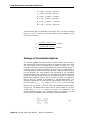
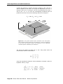
Example 2: Change of Reference System
Let’s assume that in a gait analysis laboratory the ground reaction forces
and moments are measured in the force plate local coordinate system with
the axes xf, yf, zf shown in Figure 3.4. The motion analysis system,
however, requires these loads to be computed in a laboratory fixed
coordinate system located at the corner of the force plate with the axes xL,
yL, zL. oriented as given in Figure 3.4. The x and z-axes of both coordinate
Force Plate User Manual – Bertec Corporation ! Page 15
Data Acquisition and Load Calculations
systems are pointing in opposite directions rotated by 180º, and the yaxes are parallel to each other. The origins are displaced by 20 cm in xr
direction, and 30 cm in y-direction. For such an arrangement the vector r
will be {0.2 0.3 0} m. Since the corresponding coordinate axes are
parallel to each other we have the following values for the angles θ:
θ11 = 180º, θ22 = 0º, θ33 = 180º
Figure 3.4 – The ground reaction load is measured in the force plate’s
local coordinate system denoted by the subscript “f”. Then the components
of the force and moment vectors are transferred to the laboratory
coordinate system indicated by the subscript “L”.
The rest of the angles are either 90º or -90º. Using these values the
transformation matrix is calculated as:
− 1 0 0
1 0
0 0 − 1
[T ] = 0
Using the hypothetical measured values calculated in Example 1 above in
Equations 3 and 4, we get
F 2 − 1 0 0 − 145.0 145.0
x2
Fy = 0 1 0 ⋅ 223.5 = 223.5 N
2 0 0 − 1 714.8 − 714.8
F z
Page 16
!
Force Plate User Manual – Bertec Corporation
Data Acquisition and Load Calculations
M 2 − 1 0 0 92.9
x2
M y = 0 1 0 ⋅ − 17.3 +
2 0 0 − 1 25.4
M z
0.2 145.0
0.3 × 223.5
0 − 714.8
M 2 − 307.3
x2
M y = 125.7 N ⋅ m
2 − 24.2
M z
3.3. Digital Data Acquisition
The output of Bertec force plates is a 16-bit digital signal, which is
converted to USB via an external converter (AM6500 or AM6800). The USB
output plugs into the USB port of the computer and requires no additional
A/D conversion.
The digital data acquisition software, ACQ, provided with the force plate
can be used to collect data using the digital output. The software can be
utilized to collect data from the six channels of the force plate, and save it
in a text file as column formatted text so that it can easily be imported
using spread sheet programs such as Microsoft® Excel for further analysis.
The detailed procedure on how to install and use the software is given in
Chapter 4. Digital Data Acquisition Software. For the analysis of the
collected data, please refer to 3.2 Calculation of Point of Application
for the Force and Couple.
The AM6500 series external digital converter can be powered
from the USB port of the computer. Therefore, in order to warm
up, the force plate cable should be connected, and the amplifier
should be plugged into the computer for at least 5 minutes prior
to data collection, and the computer should be turned on.
The auto zero button on the AM6800 series amplifiers is not
functional for digital data acquisition. The ACQ software has a
software zero capability (both manual and automated) to remove
signal offset.
Digital Data
Acquisition
!
Check all the cables, and make sure that they are properly
connected.
!
Turn on the external amplifiers, and allow the system to warm
up at least for 5 minutes.
!
Collect force plate data using software. Remember to remove a
baseline reading from the signals using software in order to set
the baseline to true zero (see Chapter 4. Digital Data
Acquisition Software).
Force Plate User Manual – Bertec Corporation ! Page 17
Digital Data Acquisition Software
4
Digital Data
Acquisition Software
4.1. Overview
The data acquisition software Digital Acquire (ACQ) is designed to collect
data from a single force plate, and save it to a text file. The text file is
formatted in columns so that spread sheet programs such as Microsoft®
Excel can easily be used to read and analyze data.
ACQ uses the digital USB output of the force plate to interface it. Data is
read from the force plate already in calibrated form. Therefore, no
calibration matrix or analog scale factors are needed to use the software
program. ACQ incorporates many features such as manual and automated
software zero capability, real-time display of center of pressure (CoP) and
vertical force value, fixed or variable time data acquisition periods. Digital
filters with preset cutoff frequency values can be applied to the collected
data before saving it to a file. Data channels to be saved can be selected
individually so that excessive data does not take up valuable disk space on
the computer.
Once the force plate is connected to the USB port of the computer, the
software automatically recognizes the particular plate connected, and
displays the serial number. If a cable gets disconnected, a warning
message is displayed immediately.
The ACQ software is written to collect data using the digital
output of the force plate from AM6500 or AM6800 amplifiers via
the USB port of the computer. It will not work with the analog
output of the AM65XX or AM6800 amplifiers.
Force Plate User Manual – Bertec Corporation ! Page 19
Digital Data Acquisition Software
4.2. Software Installation
The installation program for the ACQ software is provided on a CD-ROM
labeled “Digital Acquire”. The program is a self-installing program, and it
starts automatically once the disk is inserted into the CD-ROM drive of the
computer. Before proceeding with the installation make sure that the force
plate cable is connected to the force plate (8-pin round connector), and to
the external amplifier/converter (AM6500 or AM6800, 9-pin D-Sub
connector). Connect the USB cable to the amplifier/converter only.
Do not plug the USB cable into the computer yet. For a proper
installation, the USB cable should be plugged to the USB port of
the computer after the software is installed.
Software
Installation
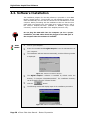
!
!
Turn on your computer.
!
The installation software starts automatically, and the following window
Insert the CD-ROM labeled Digital Acquire™ into the CD-ROM drive of
your computer.
is displayed:
Figure 4.1. Software Installation Window 1
!
The Digital Acquire™ software is installed by default under the
!
!
Click the
directory “C:\Program Files\BalanceCheck”. The installation directory
can be changed using the “Browse” button.
button.
The following window will display steps of the installation procedure:
Figure 4.2 Software Installation Window 2
Page 20
!
Force Plate User Manual – Bertec Corporation
Digital Data Acquisition Software
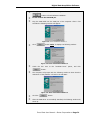
!
After you see the “Completed” message in the window click the
button to finish software installation.
!
!
Do not remove the CD-ROM yet.
Plug the USB cable into the USB port of the computer. After a few
seconds the following window will appear:
Figure 4.3. Driver Installation Window 1
!
Click
button twice To display the following window:
Figure 4.4. Driver Installation Window 2
!
Check the box next to the “CD-ROM Drive” option, and click
button.
!
The computer will prompt with the following window to show that the
USB driver of the platform is found on the CD-ROM:
Figure 4.5. Driver Installation Window 3
!
!
Click the
button.
After the USB driver is successfully installed, the following window will
show up:
Force Plate User Manual – Bertec Corporation ! Page 21
Digital Data Acquisition Software
Figure 4.6. Driver Installation Window 4
!
!
Click the
button to finish the installation procedure.
If you have any problems during the installation procedure please
contact customer service.
4.3. Using the Software
Once the software is properly installed it can be started by clicking “Start”
on the Windows® desktop and then selecting “Programs” and “Bertec
Acquire” from the list. Then click on the “Acquire” entity and the
program will start. Before starting the program, make sure that all the
cables to the force plate, external amplifier (AM6500 or AM6800), and
computer are properly connected. The data acquisition program consists of
a single window incorporating all the controls and features for collecting
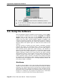
data from Bertec force plates. Figure 4.7 shows the main window of the
software.
The main window is divided into three sections: Acquisition, Acquired
Channels and Status. The Acquisition field is used to set parameters
related to data collection such as name of the file to save data, length of
data acquisition period, digital filter cutoff frequency, and selection of
manual or automatic software zero feature. The Acquired Channels field
allows selection of the data channels to be saved. The Status section
displays information related to the current status of the system including
data sampling frequency, serial number of the force plate connected to the
computer, current value of the load in Fz direction, and the location of
center of pressure (CoP) in real time. This section also includes a progress
bar displaying the percentage of data collection completed during timed
acquisition. Next to the progress bar is a message displaying whether the
force plate is loaded or unloaded.
File Name
In order to save the data to a file, the File Name field should designate a
valid file name and location. The location and name can either be entered
manually or the Choose button next to the field can be clicked to select a
specific file and location. Data will be saved as a column formatted text file
where each column contains data from a different channel. If the file name
belongs to an existing file, the program will prompt with a confirmation
message to overwrite the file before starting data acquisition.
Page 22
!
Force Plate User Manual – Bertec Corporation
Digital Data Acquisition Software
Figure 4.7 – The ACQ software consists of a single window incorporating
all of its functionality.
Data Acquisition Interval
The length for the data acquisition interval can either be fixed or variable.
A fixed time period for data acquisition can be set by checking the Timed
box, and entering a period length in seconds. Data collection can be
started by pressing the Start button, and it will stop automatically after
the specified time period runs out. If the Timed button is not checked,
then data collection period has no time limit, and the user should stop data
collection manually. For user controlled time period, data collection starts
by pressing the Start button. As soon as this button is pressed, it will
transform into a Stop button, which can then be used to terminate data
collection. The variable time data collection feature relieves the user from
the guesswork of how long the data collection period should be set in order
not to miss valuable data.
Software Zero
The ACQ software incorporates the capability of removing the signal offset
due to additional equipment on the force plate. The Software Zero feature
sets the mean values of the signals from all channels to zero. Software
Zero can be performed both manually and automatically. Pressing the Zero
Force Plate User Manual – Bertec Corporation ! Page 23
Digital Data Acquisition Software
button at the bottom of the window will remove the offset in each signal
channel. Alternatively, checking the Auto Zero box will result the software
to take a zero automatically every 3 seconds when it is not loaded. In this
case two square marks appears next to the Fz load display to indicate that
automatic software zero function is turned on. This feature is active only
when the load in the Fz channel is below a certain value (about 8 lb), and
the variations in the signal are negligible.
In order to use the automatic zero feature with heavy objects, put
the object on the force plate, zero the signals manually using Zero
button while the automatic zero function is turned on by checking
the Auto Zero box.
Applying a Digital Filter
The sampling frequency for data acquisition is fixed at a value of 1000 Hz.
The force plate itself has an analog anti-aliasing filter of 500 Hz.
Additionally, a digital software filter can be applied by selecting from a list
of preset cutoff frequencies listed in the drop-down menu of the filter box.
The drop-down menu lists nine different cutoff frequencies: 500, 333, 250,
200, 167, 143, 125, 111 and 100 Hz. The highest frequency, 500 Hz,
belongs to the anti-aliasing filter, no additional filtering is applied in the
software. The other cutoff frequencies are achieved by averaging
successive data points. In other words, averaging 3 sequential data points
yields 333 Hz, 4 data points provides 250 Hz, etc.
Selecting Data to Be Saved
Individual channel data to be saved can be chosen selectively by using the
check boxes in the Acquired Channels field. Ten check boxes are available
in this field, six of them belonging to the force and moment channels of
the force plate, two to the coordinates of the center of pressure (CoP). The
forces are saved in Newtons (N), the moments in Newton-meters (N·m),
and the coordinates of CoP in meters (m). If the “Seq” box is checked the
first column of the data file contains a sequential number starting at 1 and
incremented by 1. The last number in this column gives the total number
of data points saved for each channel. If the Time box is checked then the
data file includes a column with absolute time values corresponding to
each sample collected. The values of this column are incremented by the
amount equal to 1/fs, where fs is the sampling frequency of the data.
The Status Field
The status field displays three numerical values; the fixed sampling
frequency, the serial number of the force plate connected to the computer
and a real-time value of the force in Fz channel of the force plate. The unit
button can be used to change the unit of the displayed force. Pressing this
button swaps the unit between Newtons (N), pounds (lb) and kilograms
(kg) sequentially. In addition, a real-time display shows the location of the
Center of Pressure as a “+” cursor.
Page 24
!
Force Plate User Manual – Bertec Corporation
Digital Data Acquisition Software
Data Collection
A step-by-step procedure for data collection is as follows:
Data Collection
!
Check all the cables, and make sure that they are properly
connected.
!
Turn on the external amplifiers, and allow the system to warm
up for at least 5 minutes.
!
Start the ACQ software by double clicking on the icon on the
desktop of the Windows® operating system.
!
Make sure that the serial number of the force plate is displayed
correctly. If not, check the cable connections.
!
Enter or choose the name and location of the text file for the
data to be saved.
!
If you want a fixed time interval for data collection, check the
Timed box, and enter an interval length in seconds. If you want
to start and stop data collection manually, uncheck the Timed
box.
!
If you want the software to remove signal offset periodically by
taking a software zero, check the Auto Zero box. If you do not
check this box, zero the signals by pressing the Zero button
before each data collection.
!
If you want to filter the collected data digitally, select a cutoff
frequency from the Filter drop-down menu. Leaving the filter
cutoff at 500 Hz will result in no filtering.
!
Select the channels you want to save in the Acquired Channels
field.
!
If the Auto Zero box is not checked, then press the Zero button
for manual signal offset removal.
!
Press the Start button to start data collection.
!
If the Timed box is not checked, press the Stop button to stop
data collection process. If this box is checked, then data
acquisition will stop automatically after the specified time
interval expires.
!
Data will be saved to the file that you specified while collecting
data. Therefore, no additional action is required.
Force Plate User Manual – Bertec Corporation ! Page 25
Technical Specifications
5
Technical
Specifications
5.1. Overview
Bertec force plates are designed to cover a wide range of technical
specifications to meet the needs of clinicians and researchers from a
variety of fields. Standard force plates are available in different sizes and
load capacities, which can further be customized depending upon the
requirements of the measurements to be performed. The popular 4550,
4060 and 4080 series are the gold standard for gait analysis studies, while
larger sizes such as the 6090, 9090 and 6012 series are well suited for the
rigors of sports, ergonomics, industrial, and other dynamic biomechanical
applications.
The measured signals from strain gauge based force transducers are
amplified, filtered and digitized in the force plate, which minimizes signal
degradation due to external noise sources during analog signal
transportation. The output of the force plate is a 16-bit single channel,
serial, digital signal, which can be transported over very long distances
without any loss of quality. The digital output can be directly connected to
the USB port of the computer or it can be fed into an external amplifier
and converted into six individual analog signals to be connected to an A/D
card. All the electronics of the force plates are designed and developed by
Bertec Corporation. Analog and digital external amplifiers are designed so
that measurement load range and sensitivity can be selectively optimized.
Deciding on a particular model is not a trivial task, and requires a careful
evaluation of the needs and technical specifications of the force plates.
Type of studies to be performed, available space, other equipment to be
used with the force plate and available budget are among the many
important deciding factors in selecting force plates. Furthermore,
depending on the application a suitable force plate – amplifier combination
should be selected.
This chapter provides the basic information about the mechanical and
electrical properties of the force plates and amplifiers. If you have
additional questions, please contact Bertec Corporation (see 1.2
Customer Support).
Force Plate User Manual – Bertec Corporation ! Page 27
Technical Specifications
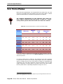
5.2. Force Plates
Basic technical specifications for the particular force plate that you have
are given on the data sheet at the back of this user guide. Table 5.1 below
gives the specifications for standard configuration force plates2.
The technical specifications for the particular force plate you
have, might be different then those given in Table 5.1. Please
check product specific data sheet at the end of this user manual.
Table 5-1 Technical Information for Various Force Plate Models
MODEL
L
W
4060-08
4060-10
600
400
4060-15
RATED
LOAD
WEIGHT
SIZE (mm)
(kg)
H
(kN)
NATURAL
FREQUENCY*
(Hz)
Fz
Fx, Fy
Fz
Fx
Fy
83
28
10
5
340
550
540
100
22.6
20
10
600
580
580
150
23.5
20
10
750
570
550
4550-08
508
464
83
26.3
10
5
380
550
540
4060-NC
600
400
100
25.9
10
5
480
500
500
800
400
100
25.2
10
5
430
460
460
150
26.2
20
10
540
460
460
6090-15
900
600
150
28.8
20
10
400
450
450
9090-15
900
900
150
31.8
20
10
320
410
410
6012-15
1200
600
150
32.5
20
10
250
450
450
4080-10
4080-15
* The given values are measured for unmounted force plates. Therefore, the actual
value might be higher. Please refer to the “Natural Frequency” section below for a
detailed explanation.
For all force plates given in Table 5-1 the maximum error due to linearity
or hysteresis is 0.2% of the full-scale output signal. Since the calibration
matrix is already stored in the force plate all outputs are calibrated and
corrected for any cross talk. Sensitivity for all force plates is 5V per rated
output. Resolution of output signal is at least 0.02% of full scale. Finally,
all force plates have an operating temperature range of 0-50 ºC.
2
Technical specifications given in this chapter may be changed without notice and
shall not be regarded as a warranty.
Page 28
!
Force Plate User Manual – Bertec Corporation
Technical Specifications
Rated Load
The rated load given in Table 5-1 is the maximum dynamic load capacity
that the force plate can measure within the linearity limit given above.
Exceeding the rated load limit may cause the force plate to behave
nonlinearly. The overload capacity for the force plates is 50%; i.e. they are
designed to sustain loads up to 1.5 times the rated load without any
damage.
Exceeding the overload capacity will result in permanent
deformation of the transducers, and damage the force plate.
Moreover, localized, high impact forces are likely to cause
physical damage to the force plate.
Natural Frequency
The natural frequency of the force plate is an important parameter for the
studies where high impact forces are involved (e.g. running, impact
landing, etc.). Impact forces are the source of band-limited excitation
where the force might contain a wide range of frequencies. These
frequencies are likely to excite fundamental structural modes of the force
plate and might cause the output signal to be unstable. Table 5-1 lists the
natural frequencies for the first structural mode of the force plates. For
impact studies, it is recommended to have the natural frequency as high
as possible. The natural frequency of the force plate is determined by
intrinsic and extrinsic factors. Intrinsic factors are physical features such
as the total mass, stiffness of the top, base and transducers. For Bertec
force plates these physical features are optimized at the design stage to
have a high natural frequency. Extrinsic factors, on the other hand, are
related to operating conditions of the force plate. Type of mounting and
condition of the mounting surface, for example, might lead to the natural
frequency of the overall system to be different than those listed in Table
5-1.
The values given in Table 5-1 are determined so that they reflect the
effect of intrinsic factors. These values are measured in an environment
where the force plate is free to move in all directions (free boundary
conditions). Adverse mounting conditions such as compliant foundations,
non-flat mounting surfaces, or improper shimming will result in a lower
natural frequency for the force plate. Using a mounting plate as described
in section 2.1 Mounting the Force Plate will result the natural frequency
to be higher than the values listed in Table 5-1.
Improper mounting of the force plate will lower the overall
natural frequency of the system. Using a mounting plate on a stiff
foundation will result in higher frequencies than those listed in
Table 5-1.
Force Plate User Manual – Bertec Corporation ! Page 29
Technical Specifications
Anchor Locations
Four anchor locations are provided on the force plate so that it can be
fastened to a mounting plate or to the floor using standard ⅜”-16 (or M81.25) machine bolts. Standard mounting plates for each force plate model
already have pre-drilled anchor locations with steel-threaded inserts.
Figure 5.1 and Table 5-2 give the exact locations of the anchor points for
standard force plates models.
Figure 5.1 – Force plate anchor locations. For numerical values of A, B, C
and D for different force plate models, please refer to Table 5-2.
Table 5-2 – Numerical values for A, B, C and D shown in Figure 5.1. All
values are in mm.
MODEL
A
B
C
D
342
552
29
24
4550-08
438
458
13
25
4060-NC
342
552
29
24
342
752
29
24
6090-15
542
860
29
24
9090-15
758
860
71
20
6012-15
540
1113
30
44
4060-08
4060-10
4060-15
4080-10
4080-15
Page 30
!
Force Plate User Manual – Bertec Corporation
Technical Specifications
5.3. Amplifiers and Signal Converters
Signal conditioning and amplification for the force plates are provided by
means of external amplifiers. Each force plate has an internal digital
preamplifier, which digitizes the analog signal from the transducer strain
gauges, and conditions it through oversampling, preliminary amplification
and filtering. The calibration matrix of the force plate is digitally stored on
the preamplifier so that the output is already calibrated data having the
units of Newtons and Newton-meters. The output of the force plate is a
16-bit digital signal using RS-485 format.
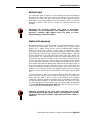
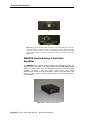
AM6500 Digital Signal Converter
The AM6500 series external converter transforms the digital output signal
to USB format, which can directly be connected to the computer (see
Figure 5.2) using a standard USB cable.
Figure 5.2 – AM6500 USB converter
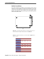
The input-output connections for the AM6500 module is shown in Figure
5.3 . The output is a standard female B-type USB connector. Next to the
connector are two LED lights. The bottom light is on when the unit is
powered via the transformer, and the top light comes on if the unit is
connected to the USB port of the computer. The input to the module is via
a 9-pin D-Sub connector located next to the power input.
Force Plate User Manual – Bertec Corporation ! Page 31
Technical Specifications
(a)
(b)
Figure 5.3 – (a) The USB output connector is a standard B-type connector.
The lower light is on when the unit is connected to power, and the top light
comes on when the unit is connected to the USB port of the computer. (b) The
input to the module is through a 9-pin D-Sub connector located next to the
power input.
AM65XX Series Analog, Fixed Gain
Amplifier
The AM65XX series external analog amplifiers are utilized to convert the
digital output of the plate to an analog signal using a fixed, pre-set gain
value. This pre-set gain value is indicated by the suffix XX in the model
identifier (i.e. 6501 – unity gain, 6504 – gain of four, etc.). These
amplifiers also provide an auto zero button to remove tare load offset (see
Figure 5.4). An external, universal power supply is used to provide power
to the amplifier.
Figure 5.4 – AM65XX analog amplifier
Page 32
!
Force Plate User Manual – Bertec Corporation
Technical Specifications
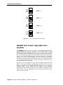
The input and output connections to the AM65XX module are shown in
Figure 5.5. The pin assignments for the analog output channels are given
in Figure 5.9 below. The output voltage range for all channels is ±5V.
Shorting pins 9 and 10 on the 15-pin output connector has the same effect
as pushing the autozero button on the AM6501.
(a)
(b)
Figure 5.5 – (a) The analog output from the AM65XX is supplied via a 15-pin
D-Sub connector (see Figure 5.9 for pin assignments). Next to the output
connector is the autozero button and two LED’s. The top LED is lit when the
signal offset is removed through autozero. The bottom LED shows that the unit
is connected to power. (b) The input to the module is through a 9-pin D-Sub
connector located next to the power input.
A blinking bottom LED indicates that the unit is not connected to a
force plate. Please check the cable connecting the force plate to
the unit.
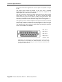
AM6504 has two additional dipswitches on the top surface to set the gain
for the output signal. Each switch has a ON/OFF setting. The gains
corresponding to each setting is given in the Figure below.
Force Plate User Manual – Bertec Corporation ! Page 33
Technical Specifications
ON
OFF
ON
OFF
ON
OFF
ON
OFF
1
2
GAIN = 1
1
2
GAIN = 2
1
2
GAIN = 5
1
2
GAIN = 10
Figure 5.6 - Gain switch settings for the AM6504
AM6800 Dual Output, Adjustable Gain
Amplifier
The AM6800 amplifier, shown in Figure 5.7, incorporates both analog and
digital outputs into one unit. The gain of the analog output is user
selectable, and has 7 different settings (1, 2, 5, 10, 20, 50, 100). A single
gain selection switch is provided for all 6 output channels (see Figure 5.8
(a)). A three-digit LED display on the front panel shows the current gain
setting. The channel signal indicators show the polarity of the analog
output for the six force plate channels. The auto zero button is utilized to
remove tare load offset from each channel output. The mains power input
is a universal input with the range 100-240 V, 50-60 Hz (Figure 5.8 (b)).
The digital output is a USB signal.
If the unit is not connected to a force plate, the digital display will read
“P L 7 ”. After the force plate is properly connected to the unit, when the
amplifier is turned on, the display will briefly (about 0.5 sec.) show the
message “C A L ”, which indicates that the amplifier has successfully
recognized the force plate. Finally, the gain setting will display on the
digital readout. The pin assignments for the analog output channels are
given in Figure 5.9 below.
Page 34
!
Force Plate User Manual – Bertec Corporation
Technical Specifications
Figure 5.7 – AM6800 dual output, variable gain signal amplifier with auto zero.
(a)
(b)
Figure 5.8 – (a) Front panel of AM6800 amplifier. Of the two lights between
the auto zero button and power switch the bottom one comes on when the unit
is switched on, and the top light is lit after the auto zero button is pressed. (b)
The input and output to the unit is through 9-pin and 15-pin female D-Sub
connectors respectively.
A 19” rack mounting adaptor for AM6800 amplifier is available upon
request from Bertec Corporation.
General Specifications
The AM65XX series and AM6800 amplifiers provide a ±5 V full-scale
calibrated analog output per rated load range for each of the six force
plate channels. For example, if the force plate has a ±10 kN load range for
the Fz channel, then for a gain of unity, the –5.00 V output corresponds to
–10 kN, and +5.00 V stands for +10 kN (i.e. a sensitivity of 0.5 mV/N).
The analog gain used in data acquisition represents a trade-off between
maximum load range and force plate sensitivity. If the same force plate
above is used with an amplifier gain of 5, then the load range will be
limited to ±2 kN. This means the plate now has an increased sensitivity of
2.5 mV/N. The analog load scale factors for specific force plates, given on
Force Plate User Manual – Bertec Corporation ! Page 35
Technical Specifications
the product data sheet supplied with the force plate are specified for a gain
of one.
The analog output signals are filtered so that they have a standard
bandwidth of 500 Hz. The actual analog gain ratios are applied to the
digital signal with an accuracy of 99.997%.
The auto zero button removes the signal offset and sets the analog output
signal within ±5 mV. This feature can be used to increase the useful
measurement range of the force plate by shifting the signal baseline. Note
that auto zero might not set the mean value of the signal to true zero.
Therefore, an additional offset removal through software is suggested.
The digital input to all external amplifiers and signal converters is a female
9-pin D-Sub connector, whereas the analog output is in the form of a
female 15-pin D-Sub connector with the pin assignments shown in Figure
5.9. Shorting pins 9 and 10 has the same effect as pushing the autozero
button on the AM6501 and AM6800.
8
7
15
6
14
5
13
4
12
3
11
2
10
1
9
CH1 : Pin 3
CH2 : Pin 4
CH3 : Pin 5
CH4 : Pin 6
CH5 : Pin 7
CH6 : Pin 8
GRND : Pin 10
Autozero: Pin 9
Figure 5.9 – Pin configuration for the standard analog 15-pin female DSub connector for the AM65XX and AM6800 amplifiers. The output range
for each channel is ±5V. Shorting pins 9 and 10 has the same effect as
pushing the autozero button.
Page 36
!
Force Plate User Manual – Bertec Corporation