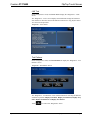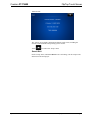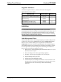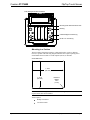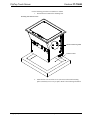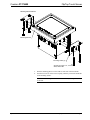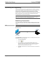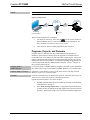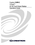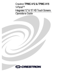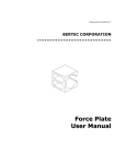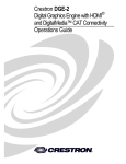
1
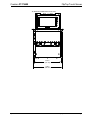
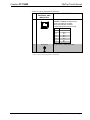
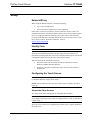
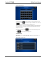
Crestron FT-TS600 FlipTop™ Touch Screen Operations & Installation Guide Regulatory Compliance This product is Listed to applicable UL Standards and requirements by Underwriters Laboratories Inc. As of the date of manufacture, the FT-TS600 has been tested and found to comply with specifications for CE marking and standards per EMC and Radiocommunications Compliance Labelling. Federal Communications Commission (FCC) Compliance Statement This device complies with part 15 of the FCC Rules. Operation is subject to the following conditions: (1) This device may not cause harmful interference and (2) this device must accept any interference received, including interference that may cause undesired operation. CAUTION: Changes or modifications not expressly approved by the manufacturer responsible for compliance could void the user’s authority to operate the equipment. NOTE: This equipment has been tested and found to comply with the limits for a Class B digital device, pursuant to part 15 of the FCC Rules. These limits are designed to provide reasonable protection against harmful interference in a residential installation. This equipment generates, uses and can radiate radio frequency energy and, if not installed and used in accordance with the instructions, may cause harmful interference to radio communications. However, there is no guarantee that interference will not occur in a particular installation. If this equipment does cause harmful interference to radio or television reception, which can be determined by turning the equipment off and on, the user is encouraged to try to correct the interference by one or more of the following measures: • Reorient or relocate the receiving antenna • Increase the separation between the equipment and receiver • Connect the equipment into an outlet on a circuit different from that to which the receiver is connected • Consult the dealer or an experienced radio/TV technician for help Industry Canada (IC) Compliance Statement CAN ICES-3(B)/NMB-3(B) The specific patents that cover Crestron products are listed at patents.crestron.com. Crestron, the Crestron logo, Cresnet, Crestron Studio, Crestron Toolbox, DigitalMedia, FlipTop, Rava, Smart Graphics, SmartObjects, TouchPoint and VT Pro-e are either trademarks or registered trademarks of Crestron Electronics, Inc. in the United States and/or other countries. Window is either a trademark or registered trademark of Microsoft Corporation in the United States and/or other countries. Other trademarks, registered trademarks, and trade names may be used in this document to refer to either the entities claiming the marks and names or their products. Crestron disclaims any proprietary interest in the marks and names of others. Crestron is not responsible for errors in typography or photography. This document was written by the Technical Publications department at Crestron. ©2013 Crestron Electronics, Inc. Crestron FT-TS600 FlipTop Touch Screen Contents FlipTop Touch Screen: FT-TS600 1 Introduction ............................................................................................................................... 1 Features and Functions ................................................................................................ 1 Specifications .............................................................................................................. 4 Physical Description .................................................................................................... 6 Setup ........................................................................................................................................ 12 Network Wiring ......................................................................................................... 12 Identity Code ............................................................................................................. 12 Configuring the Touch Screen ................................................................................... 12 Supplied Hardware .................................................................................................... 24 Installation ................................................................................................................. 24 Hardware Hookup ..................................................................................................... 28 Recommended Cleaning ............................................................................................ 29 Uploading and Upgrading ........................................................................................................ 30 Establishing Communication ..................................................................................... 30 Programs, Projects, and Firmware ............................................................................. 31 Program Checks ........................................................................................................ 32 Problem Solving ...................................................................................................................... 33 Troubleshooting......................................................................................................... 33 Reference Documents ................................................................................................ 33 Further Inquiries ........................................................................................................ 33 Future Updates .......................................................................................................... 34 Return and Warranty Policies .................................................................................................. 35 Merchandise Returns / Repair Service ...................................................................... 35 Crestron Limited Warranty........................................................................................ 35 Operations & Installation Guide – DOC. 7585A Contents • i Crestron FT-TS600 FlipTop Touch Screen FlipTop Touch Screen: FT-TS600 Introduction The FT-TS600 FlipTop™ Touch Screen by Crestron® provides a configurable control and connectivity solution in a stylish, flush mount tabletop design. Flipping open the “FlipTop” lid exposes a brilliant 5” (127 mm) color touch screen, gracefully angled for easy operation and viewing. The built-in connection compartment keeps interface cables and connectors at the ready for plugging in laptop computers, mobile devices, AV source, and other equipment. Features and Functions • • • • • • • • • • • • • • Flush mount tabletop control and connectivity in one stylish FlipTop design Integrated 5” capacitive color touch screen with Smart Graphics™1 support High performance H.264 streaming video over Ethernet Seamless integration with Crestron DigitalMedia 5 soft-touch capacitive buttons for common functions Hands-free audio conferencing using Rava™ SIP intercom technology2 Customizable audio feedback Built-in microphone and speaker Balanced line out for amplification of the speaker signal PoE+ (Power over Ethernet) 1-wire touch screen communication and power Configurable connection compartment allows versatile combinations of pull-out cables, cable retractors, connector plates, and AC power outlets Tapered cable notch allows lid to be closed with cables plugged in Universal cutout size fits all new and future FlipTops Black anodized or brushed aluminum finish 1. Supports Smart Graphics only. Not compatible with “traditional” UI projects. 2. Supports audio conferencing with another Rava-enabled device over an IP network, or with any telephone device through integration with a SIP-compatible phone system or SIP server. Operations & Installation Guide – DOC. 7585A FlipTop Touch Screen: FT-TS600 • 1 Crestron FT-TS600 FlipTop Touch Screen The FlipTop Touch Screen is an ideal complement to a DigitalMedia™ transmitter or any other AV interface device. It provides an intuitive and inviting “front end” for the more complex and mundane technology hidden away beneath the tabletop. The integrated touch screen can provide control for an entire room, offering a fully customizable user interface for selecting presentation sources, adjusting audio levels, dimming the lights, and even calling for lunch service. Advanced capabilities include displaying full-motion video and hands-free audio conferencing.1 FlipTop Design Handsomely finished in a choice of black anodized or brushed aluminum, Crestron FlipTops lend a contemporary metallic accent to conference tables and podiums. The FT-TS600 installs cleanly in virtually any flat, horizontal surface up to 1 3/4” (44 mm) thick. Beveled edges provide for a nearly flush appearance. The FlipTop lid flips open with just the tip of a finger to access the touch screen and connection compartment. Once connections and touch screen settings are made, the lid can be closed. A generous, tapered notch at the front of the lid opening allows interface cables to remain connected even when the lid is closed. Connection Compartment The FT-Ts600 is highly configurable to provide a well organized connectivity solution tailored to each unique application. It provides options for both pullout and panel-mounted connectors, with or without AC power outlets. It comes standard with two cable pass-through plates and four blank plates, all of which can be swapped out for a choice of cable retractors, connector plates, and AC power outlet modules. • Cable Pass-Through Plates – Each cable pass-through plate provides four grommeted holes to accommodate Crestron Certified Interface Cables2 and other AV, data, and communication cables. The user end of each cable stows neatly within the connection compartment ready for use while excess cable simply drops out of sight below the cable pass-through plate. The grommets provide a smooth, slippery surface for easy pullout of each cable. Blank caps are also provided to cover any unused holes. The cable pass-through plates are positioned at the left and right sides of the connection compartment. The FT-TS600 supports one or two cable pass-through plates. Two are included. • Cable Retractors – For an even more refined cable management solution, the FT-TS600 accommodates up to six Crestron CBLR Cable Retractors2. Crestron cable retractors feature a patent pending, lever actuated retraction mechanism that ensures smooth operation while eliminating hanging cable loops beneath the table. Up to three cable retractors can be installed in place of each cable pass-through plate, allowing for a total of six cable retractors. • Connector Plates – If panel mounted connectors are preferred, the FT-TS600 can accommodate up to four FTA-CP Connector Plates2. Connector plates are offered with a variety of common AV and data connector types. Custom connector plates may also be fabricated by the installer using the blank plates provided. All four connector plates are positioned at the center of the connection compartment. 1. Supports audio conferencing with another Rava-enabled device over an IP network, or with any telephone device through integration with a SIP-compatible phone system or SIP server. 2. Item(s) sold separately. 2 • FlipTop Touch Screen: FT-TS600 Operations & Installation Guide – DOC. 7585A Crestron FT-TS600 FlipTop Touch Screen • AC Power Outlet Modules – To provide power for laptops and other portable devices, the FT-TS600 can be equipped with up to four AC power outlets. A single FTA-PWR-102 Dual AC Power Outlet Module1 can be installed in place of the center two connector plates or two FTA-PWR-102s can be installed in place of all four connector plates. Integrated 5” Touch Screen The FT-TS600 features a large 5” (127 mm) capacitive touch screen display that wakes when the FlipTop lid is opened and goes to sleep when the lid is closed. Smart Graphics technology provides a stunning custom user interface with fluid gesturedriven controls, animated feedback, metadata, embedded apps, and high performance H.264 video. Five soft-touch capacitive buttons are also provided for quick access to commonly used functions. Streaming Video High performance streaming video capability makes it possible to preview a video source during a presentation or see a live camera image while video conferencing, right on the FlipTop screen. Support for H.264 and MJPEG formats allows the FT-TS600 to display streaming video from a Web camera, a streaming server (Crestron CEN-NVS2001 or similar), or a DigitalMedia switcher1, 2. Video is delivered to the touch screen over Ethernet, eliminating the need for any extra video wiring. For more information on video streaming, refer to Answer ID #5195 at http://support.crestron.com/app/answers/detail/a_id/5195/kw/streaming%20video. Hands-Free Audio Conferencing Using Rava SIP intercom technology, the FT-TS600 enables hands-free VoIP communication between any two Rava-enabled Crestron touch screens. Rava works over Ethernet, supporting audio conferencing3, intercom, video intercom4, paging, and room monitoring without any special wiring. VoIP phone capability is also possible through integration with a SIP-compatible IP phone system or SIP server, allowing hands-free telephone and teleconferencing functionality complete with speed dialing, caller ID, custom ringers, and other enhancements. Built-in echo cancellation affords true duplex performance for clear, seamless voice communication using the FT-TS600’s integrated microphone and speaker. Line Output In addition to its onboard speaker, the FT-TS600 includes a balanced line level audio output, allowing the speaker signal to be routed to the room’s audio system. Amplifying the FlipTop’s audio signal through the room speakers enhances its audio conferencing capabilities, allowing a small group of individuals to participate in a conference call using a single FT-TS600.2 1. Item(s) sold separately. 2. Streaming output is currently available on the following DigitalMedia switcher modules: DM-MD8X8, DM-MD8X8-RPS, DM-16X16, DM-16X16-RPS, DM-32X32, and DM-32X32-RPS. 3. Supports audio conferencing with another Rava-enabled device over an IP network, or with any telephone device through integration with a SIP-compatible phone system or SIP server. 4. H.264 compatible IP camera required. Operations & Installation Guide – DOC. 7585A FlipTop Touch Screen: FT-TS600 • 3 Crestron FT-TS600 FlipTop Touch Screen Power over Ethernet Using PoE+ technology, the FT-TS600 gets its operating power right through the LAN wiring. PoE eliminates the need for a local power supply or any dedicated power wiring. A PoE+ capable power source (CEN-SWPOE-16, sold separately, or similar) is required to power the FT-TS600. Specifications Specifications for the FT-TS600 are listed in the following table. FT-TS600 Specifications SPECIFICATION DETAILS Touch Screen Display Display Type TST active matrix color LCD Size 5 inch (127 mm) diagonal Aspect Ratio 15:9 WVGA Resolution 800 x 480 pixels Brightness 300 nits (cd/m ) Contrast 450:1 Color Depth 24-bit, 16.7 million colors Illumination Edgelit LED Viewing Angle ±69º horizontal, +62º /-64º vertical Touch Screen Projected capacitive 2 Buttons Hard Keys (5) Projected capacitive push buttons, programmable, pre-labeled with icons for “Power”, “Home”, “Lights”, “Up”, and “Down” Memory LPDDR2 RAM 1 GB Flash 4 GB Maximum Project Size 512 MB Graphics Engine Supports Smart Graphics* Communications Ethernet 10/100 Mbps, auto-switching, auto-negotiating, auto-discovery, full/half duplex, DHCP, IEEE 802.3at Type 2 compliant Video Streaming Formats H.264 (MPEG-4 part 10 AVC), MJPEG Audio Features Built-in microphone and speaker, Rava SIP Intercom, line out (same signal as speaker) Audio Feedback Format MP3 Power Requirements Power over Ethernet IEEE 802.3at Type 2 Class 4 PoE+ powered device (Continued on following page) 4 • FlipTop Touch Screen: FT-TS600 Operations & Installation Guide – DOC. 7585A Crestron FT-TS600 FlipTop Touch Screen FT-TS600 Specifications (Continued) SPECIFICATION DETAILS Environmental Temperature 32º to 112º F (0º to 45º C) Humidity 10% to 90% RH (non-condensing) Heat Dissipation 46 Btu/h Enclosure Chassis Metal, black Cover Aluminum, black anodized or brushed aluminum finish Mounting Flush tabletop mount, 1 3/4 in (44 mm) maximum surface thickness, 6 1/4” (159 mm) deep x 7 1/2 in (190 mm) wide cutout (template provided) Dimensions Height 7.06 in (180 mm) 10.80 in (275 mm) with lid open Width 7.98 in (203 mm) 9.19 in (234 mm) with mounting brackets Depth 6.77 in (172 mm) 7.88 in (200 mm) with lid open Weight 5.1 lb (2.3 kg) Available Models FT-TS600-B FlipTop Touch Screen, Black Anodized FT-TS600-BALUM Flip Top Touch Screen, Brushed Aluminum [Special Order] Available Accessories * CBL Series Crestron Certified Interface Cables CBLR Series Cable Retractors CBLRA-BRKT-3-H Horizontal Mounting Option for CBLR CBLRA-INSERT-2WIRE 2-Wire Insert for Cable Retractor Option CBLRA-INSERT-BLANK Blank Insert for Cable Retractor Option CEN-NVS200 Network Video Streamer CEN-SWPOE-16 16-Port Managed PoE Switch FTA-CP-DP-101 FlipTop DisplayPort Connector Plate FTA-CP-HDMI-101 FlipTop HDMI Connector Plate FTA-CP-RCA-103 FlipTop 3 RCA Connector Plate FTA-CP-RJ45-102 FlipTop 2 RJ45 Connector Plate FTA-CP-USB-102 FlipTop 2 USB Connector Plate FTA-PWR-102 FlipTop Dual AC Power Outlet Module, NEMA 5 VMK-WIN TouchPoint Virtual Mouse & Keyboard ® Software for Windows ® Supports Smart Graphics only. Not compatible with “traditional” UI projects. Operations & Installation Guide – DOC. 7585A FlipTop Touch Screen: FT-TS600 • 5 Crestron FT-TS600 FlipTop Touch Screen Physical Description This section provides information on the connections, controls, and indicators available on the FT-TS600. FT-TS600 Overall Dimensions (Top View) 7.98 in (203 mm) 6.22 in (158 mm) 6.77 in (172 mm) 6 • FlipTop Touch Screen: FT-TS600 Operations & Installation Guide – DOC. 7585A Crestron FT-TS600 FlipTop Touch Screen FT-TS600 Overall Dimensions (Front View) 6.72 in (171 mm) 7.28 in (185 mm) Operations & Installation Guide – DOC. 7585A FlipTop Touch Screen: FT-TS600 • 7 Crestron FT-TS600 FlipTop Touch Screen FT-TS600 Overall Dimensions (Side View) 7.88 in (200 mm) 3.75 in (95 mm) 7.06 in (180 mm) 6.94 in (177 mm) 5.12 in (130 mm) 6.07 in (155 mm) 8 • FlipTop Touch Screen: FT-TS600 Operations & Installation Guide – DOC. 7585A Crestron FT-TS600 FlipTop Touch Screen FT-TS600 (Oblique View) Microphone Speaker Operations & Installation Guide – DOC. 7585A FlipTop Touch Screen: FT-TS600 • 9 Crestron FT-TS600 FlipTop Touch Screen FT-TS600 (Bottom View) 1 2 4 3 6 5 Connectors, Controls, and Indicators 1 # CONNECTORS , CONTROLS, AND INDICATORS DESCRIPTION 1 AUD OUT (1) 3-pin 3.5 mm detachable terminal block; Balanced mono line level audio output; Output impedance: 100 Ω; Maximum output level: 4 Vrms G 2 COMPUTER Pin 1 Pin 2 (1) USB Type B female; USB computer console port (cable included) PIN Pin 3 Pin 4 3 PWR LED 4 HW-R Button DESCRIPTION 1 +5 Vdc 2 Data - 3 Data + 4 Ground (1) Dual color LED; Yellow indicates operating power supplied via PoE; Green indicates device is ready (1) Recessed miniature push button for hardware reset (Continued on following page) 10 • FlipTop Touch Screen: FT-TS600 Operations & Installation Guide – DOC. 7585A Crestron FT-TS600 FlipTop Touch Screen Connectors, Controls, and Indicators (Continued) 1 # CONNECTORS , CONTROLS, AND INDICATORS 5 LAN PoE 2 Pin 8 6 Pin 1 G (Ground) DESCRIPTION (1) 8-pin RJ-45 with two LED indicators; 10BASE-T/100BASE-TX Ethernet port; Power over Ethernet compliant; Green LED indicates link status; Yellow LED indicates Ethernet activity PIN DESCRIPTION 1 2 3 4 5 6 7 8 TX + TX RX + DC + DC + RX DC DC - (1) 6-32 screw, chassis ground lug 1. An interface connector for the AUD OUT port is provided with the unit. 2. PoE+ dc power can also be available on a TX/RX pair. Operations & Installation Guide – DOC. 7585A FlipTop Touch Screen: FT-TS600 • 11 Crestron FT-TS600 FlipTop Touch Screen Setup Network Wiring When wiring the Ethernet network, consider the following: • Use Crestron Certified Wire. • Use Crestron power supplies for Crestron equipment. Unlike other Crestron network devices, the FT-TS600 does not use Cresnet® for communications between the device and the control system. The FT-TS600 requires the use of a high-speed Ethernet connection for control system communications. For general information on connecting Ethernet devices in a Crestron system, refer to the Crestron e-Control Reference Guide (Doc. 6052) at www.crestron.com/manuals. Identity Code NOTE: The latest software can be downloaded at www.crestron.com/software. The IP ID is set within theFT-TS600’s IP table using Crestron Toolbox™. For information on setting an IP table, refer to the Crestron Toolbox help file. The IP IDs of multipleFT-TS600 devices in the same system must be unique. When setting the IP ID, consider the following: • The IP ID of each unit must match an IP ID specified in the Crestron Studio™ or SIMPL Windows program. • Each device using IP to communicate with a control system must have a unique IP ID. Configuring the Touch Screen NOTE: The only connection required to configure the touch screen is power. Refer to “Hardware Hookup” on page 28 for details. NOTE: The FT-TS600 can take up to 45 seconds to boot to a display after initial power up. Access the Setup Screens The “Setup” menu is the starting point for configuring the FT-TS600. NOTE: If no project has been loaded or if an invalid project has been loaded, the screen displays a message saying “There is no display project to start. [Touch Screen to Enter Setup…]” The setup screens enable basic configuration procedures prior to regular operation of the touch screen. 12 • FlipTop Touch Screen: FT-TS600 Operations & Installation Guide – DOC. 7585A Crestron FT-TS600 FlipTop Touch Screen During regular operation of the touch screen, there are two ways to activate the setup functions: 1. Place a button on the project main page and assign the reserved join number (17242) that activates setup. 2. Press hard keys 1, 2, 3 and 4, to the right of the touch screen display, in sequence twice (i.e., press 1, 2, 3, 4, 1, 2, 3, 4) within a 5 second period. Button Numbering 1 2 3 4 The “Setup” menu is displayed. “Setup” Menu The “Setup” menu is comprised of buttons for Ethernet Setup, IP Table Setup, Audio Setup, Display Setup, Standby Timeout and Diagnostics. In addition, there is an About button that provides information about the touch screen and a Save & Exit button. The functions of each are detailed in the following pages of this guide. Operations & Installation Guide – DOC. 7585A FlipTop Touch Screen: FT-TS600 • 13 Crestron FT-TS600 FlipTop Touch Screen Ethernet Setup On the “Setup” menu, touch Ethernet Setup to display the “Ethernet Setup” menu. “Ethernet Setup” Menu The “Ethernet Setup” menu displays the touch screen’s Mac and IP Address, Subnet Mask, Def Router, Primary DNS, Secondary DNS, Hostname and Domain. There are controls for turning DHCP On or Off as well as a Set Static IP Address Settings button, which provides access to controls which allow editing of these settings. This screen also contains a Link indicator to show the status of the Ethernet connection. Touch Set Static IP Address Settings to display the “Ethernet Setup – Static IPs” screen. “Ethernet Setup – Static IPs” Screen To edit the Static IP Address, Static Subnet Mask, Static Default Router, Preferred DNS or Alternate Preferred DNS, touch the button directly under the label for the entry to edit. The on-screen numeric keypad opens. 14 • FlipTop Touch Screen: FT-TS600 Operations & Installation Guide – DOC. 7585A Crestron FT-TS600 FlipTop Touch Screen On-Screen Numeric Keypad Use the keypad to make the new entry. Touch the “x” in the text field to clear any previous entry. Touch or to delete the last digit. Touch Save to save a new entry to return to the “Ethernet Setup – Static IPs” screen. After new settings have been saved, touch Reboot Required to Apply IP Changes on the “Ethernet Setup – Static IPs” screen to reboot the touch screen, so the new settings can take effect. If not making any changes, touch Touch to return to the “Ethernet Setup” menu. again to return to the “Setup” menu. IP Table Setup On the “Setup” menu, touch IP Table Setup to display the “Ethernet Setup – IP Table” menu. “Ethernet Setup –IP Table” Menu Operations & Installation Guide – DOC. 7585A FlipTop Touch Screen: FT-TS600 • 15 Crestron FT-TS600 FlipTop Touch Screen The “Ethernet Setup – IP Table” menu displays up to four IP table settings, each of which has an Online indicator. To add or edit an entry, touch the Add/Edit button to its left. The “Ethernet Setup – Edit IP Table Entry” screen is displayed. “Ethernet Setup –Edit IP Table Entry” Screen Touch the field below CIP ID to display the on-screen hex keypad. On-Screen Hex Keypad Use the keypad to make the new entry. Touch the “x” in the text field to clear any previous entry. Touch or to delete the last digit. Touch Save to save a new entry to return to the “Ethernet Setup – Edit IP Table Entry” screen. Touch the field below IP Address/Hostname to display the on-screen keyboard. 16 • FlipTop Touch Screen: FT-TS600 Operations & Installation Guide – DOC. 7585A Crestron FT-TS600 FlipTop Touch Screen On-Screen Keyboard Use the keyboard to make the new entry. Touch Cancel to return to the “Ethernet Setup – Edit IP Table Entry” screen. Touch the “x” in the text field to clear any to delete the last digit. Touch Save to save a new entry previous entry. Touch and return to the “Ethernet Setup – Edit IP Table Entry” screen. On the “Ethernet Setup – Edit IP Table Entry” screen, touch Save Entry to save the current entry or Delete Entry to clear it. If not making any changes, touch Table” menu. Touch to return to the “Ethernet Setup –IP again to return to the “Setup” menu. Audio Setup On the “Setup” menu, touch Audio Setup to display the “Audio Setup” screen. “Audio Setup” Screen The “Audio Setup” screen provides controls for muting (or unmuting) the audio, adjusting level for both Master Volume and Media Volume, as well as a control for playing a test .wav file. The Media Volume controls adjust H.264 streaming media Operations & Installation Guide – DOC. 7585A FlipTop Touch Screen: FT-TS600 • 17 Crestron FT-TS600 FlipTop Touch Screen level in relation to the Master Volume controls. Use Audio Select to choose whether audio plays through the internal speaker or via the line output. Touch to return to the “Setup” menu. Display Setup On the “Setup” menu, touch Display Setup to enter the “Display Setup” screen. “Display Setup” Screen The “Display Setup” screen provides controls for LCD (Screen) Brightness and On and Off controls for Hard Key Wakes LCD. Touch to return to the “Setup” menu. Standby Timeout On the “Setup” menu, touch Standby Timeout to display the “Standby Timeout” screen. “Standby Timeout” Screen The “Standby Timeout” screen provides controls to adjust standby timeout from 0 to 120 minutes. 18 • FlipTop Touch Screen: FT-TS600 Operations & Installation Guide – DOC. 7585A Crestron FT-TS600 FlipTop Touch Screen Touch to return to the “Setup” menu. Diagnostics On the “Setup” menu, touch Diagnostics to display the “Diagnostics” menu. “Diagnostics” Menu The “Diagnostics” menu displays the CPU temperature, Available Memory and contains controls to run a Keypad Test, Touch Test, LAN Test, Rava Test, and Mic Test. In addition there are controls to initiate touch screen calibration and to open various test screens. These are explained in the paragraphs that follow. Keypad Test On the “Diagnostics” menu, touch Keypad Test to display the “Diagnostics – Keypad Test” screen. “Diagnostics – Keypad Test” Screen The “Diagnostics - Keypad” screen can be used to test the function of the hard key push buttons on the right side of the screen. When a button is pressed, its corresponding indication on the screen lights. Touch Operations & Installation Guide – DOC. 7585A to return to the “Diagnostics” menu. FlipTop Touch Screen: FT-TS600 • 19 Crestron FT-TS600 FlipTop Touch Screen Touch Test On the “Diagnostics” menu, touch Touch Test to display the touch test screen. Touch Test Screen The touch test screen can be used to test the function of the screen. When a location button (the “x” buttons or the “o” button) is touched, its indication on the screen lights. This screen also contains a Calibrate button to initiate touch screen calibration. During touch screen calibration, a crosshair appears at the center of the screen. Touch the center of the crosshair, which then moves to the upper left part of the screen. Touch the center of the crosshair and it moves to another part of the screen. Continue touching the center of the crosshair until calibration is complete. NOTE: When touching the screen during calibration, be as accurate as possible. Touch to return to the “Diagnostics” menu. Calibrate On the “Diagnostics” menu, touch Calibrate to initiate the screen calibration procedure. Refer to “Touch Test” above for details. 20 • FlipTop Touch Screen: FT-TS600 Operations & Installation Guide – DOC. 7585A Crestron FT-TS600 FlipTop Touch Screen LAN Test On the “Diagnostics” menu, touch LAN Test to display the “Diagnostics – LAN” screen. The “Diagnostics – LAN” screen displays current Ethernet settings and contains a Link indicator to show the status of the Ethernet connection. A Ping Default Router Test control is also provided. “Diagnostics – LAN” Screen Test Patterns On the “Diagnostics” menu, touch Test Patterns to display the “Diagnostics - Test Patterns” screen. “Diagnostics - Test Patterns” Screen The “Diagnostics - Test Patterns” screen contains buttons for selecting the different available test patterns: Display Color Bars, Display Vertical Lines, Display Gray Scale, Display Grid Pattern and Display Test Pattern. Touch Operations & Installation Guide – DOC. 7585A to return to the “Diagnostics” menu. FlipTop Touch Screen: FT-TS600 • 21 Crestron FT-TS600 FlipTop Touch Screen Rava Test On the “Diagnostics” menu, touch Rava Test to display the “Diagnostics – Rava” screen. “Diagnostics - Rava” Screen The “Diagnostics - Rava” screen provides controls for testing the use of Crestron’s Rava™ SIP Intercom with the FT-TS600. It can be used to test projects and settings. If the intercom works but the project does not, there is an issue with the project; if the intercom does not work, there is an issue with the settings. Touch to return to the “Diagnostics” menu. Mic Test On the “Diagnostics” menu, touch Mic Test to begin a microphone test. The touch screen records audio for five seconds and then plays back the recorded sound. The built-in microphone (located above the touch screen display) will be used to record your voice and play it back to confirm the microphone is functioning. When playback is finished, the display returns to the “Diagnostics” menu. Touch to return to the “Setup” menu. About On the “Setup” menu, touch About to display the “About” screen. 22 • FlipTop Touch Screen: FT-TS600 Operations & Installation Guide – DOC. 7585A Crestron FT-TS600 FlipTop Touch Screen “About” Screen The “About” screen displays information about the touch screen, including the currently loaded firmware and operating system versions. Touch to return to the “Setup” menu. Save & Exit On the “Setup” menu, touch Save & Exit to save all settings, exit the setup screens and return to the main project. Operations & Installation Guide – DOC. 7585A FlipTop Touch Screen: FT-TS600 • 23 Crestron FT-TS600 FlipTop Touch Screen Supplied Hardware The hardware supplied with the FT-TS600 is listed in the following table. Supplied Hardware for the FT-TS600 DESCRIPTION PART NUMBER QUANTITY Metal, Plate, Mounting 2036985 2 Screw, 10-32 x 2”, Steel, Socket HD, Zinc 2037109 4 Small Hole Plug 2036647 4 Large Hole Plug 2036649 4 Small Bushing, 5/16” ID, 0.5” OD 2009522 4 Large Bushing, 0.55” ID, 0.80” OD 2010496 4 Installation NOTE: To prevent overheating, do not operate this product in an area that exceeds the environmental temperature range listed in the table of specifications. Consideration must be given if installed in a closed assembly, inside a closed desk or in a closed podium since the operating ambient temperature of these environments may be greater than the room ambient temperature. Contact with thermal insulating materials should be avoided on all sides of the unit. Cable Management Plates The FT-TS600 ships with two cable management plates pre-installed. These provide a pullout cable solution for the AUD OUT (audio output) COMPUTER and LAN cables. A 6 foot (1.8 meter) USB Type A to Type B cable is included for the COMPUTER connection. Cables are looped through the cable management plates. The included bushings must be installed before mounting the FT-TS600 in a surface. For a neat appearance, any unused openings can be filled using the included hole plugs. The only tool required is a Phillips screwdriver. 1. Remove the two cable management plates and retain the 06-32 x 1/4” screw that holds each one in place. 2. Place the bushings on the cables (eight bushings supplied). 3. Thread the cables through the appropriate slots on each plate. 4. Snap the bushings into the plate slots. 5. Feed all excess cable through the opening. 6. Attach each plate by first sliding its dovetail into the slot toward the rear of the inside of the FT-TS600, then dropping the front into place and securing it with the 06-32 x 1/4” screw from step 1. Refer to the following illustration. 24 • FlipTop Touch Screen: FT-TS600 Operations & Installation Guide – DOC. 7585A Crestron FT-TS600 FlipTop Touch Screen Cable Management Plate Installation Mounting Plate Dovetail Inserts Here Bushing Cable Management Plates (2) 06-32 x 1/4” Screws (2) Mounting in a Surface The FT-TS600 is designed to mount in a horizontal surface, such as a desktop, lectern, or podium. The following diagram illustrates the required opening size to accommodate the FT-TS600. A cutout template (40143) is included. Cutout Dimensions 7 1/2 in (190 mm) 6 1/4 in (159 mm) Maximum Radius 1/8 in (4 mm) NOTE: Before inserting the FT-TS600 in the mounting hole, ensure that all required cables have been installed. Tools required: • Phillips screwdriver • #10 Allen wrench Operations & Installation Guide – DOC. 7585A FlipTop Touch Screen: FT-TS600 • 25 Crestron FT-TS600 FlipTop Touch Screen Use the following procedure to mount the FT-TS600. 1. Position the FT-TS600 in the mounting hole. Mounting Plate Stud Locations Studs for Mounting Plate Surface Cutout 2. 26 • FlipTop Touch Screen: FT-TS600 Install the four #10-32 socket screws (2037109) in the metal mounting plates (2036985) (two screws per plate). Refer to the following illustration. Operations & Installation Guide – DOC. 7585A Crestron FT-TS600 FlipTop Touch Screen Mounting Plate Installation Mounting Surface Mounting Plates (2) Screws (4) #10-32 x 2”, Steel, Socket HD 3. Slide the mounting plates over the studs on each side of the FT-TS600. 4. Turn the four #10-32 socket screws equally, until they contact the underside of the mounting surface. NOTE: Do not overtighten the #10 screws as this may damage the surface or the unit. Operations & Installation Guide – DOC. 7585A FlipTop Touch Screen: FT-TS600 • 27 Crestron FT-TS600 FlipTop Touch Screen Hardware Hookup Make the necessary connections as called out in the illustration that follows this paragraph. Apply power after all connections have been made. When making connections to the FT-TS600, note the following: • Use Crestron power supplies for Crestron equipment. • The included cable cannot be extended. Hardware Connections for the FT-TS600 AUD OUT: To Balanced Line Level Input COMPUTER: To PC LAN PoE: 10BASE-T / 100BASE-TX Ethernet to LAN Ground CAUTION: Do not apply excessive pressure to the touch screen display during handling. Doing so can crack the screen and damage the touch screen. NOTE: Ensure the unit is properly grounded by connecting the chassis ground lug to an earth ground (building steel). NOTE: To prevent overheating, do not operate this product in an area that exceeds the environmental temperature range listed in the table of specifications. 28 • FlipTop Touch Screen: FT-TS600 Operations & Installation Guide – DOC. 7585A Crestron FT-TS600 FlipTop Touch Screen Recommended Cleaning Keep the surface of the touch screen free of dirt, dust or other materials that could degrade optical properties. Long-term contact with abrasive materials can scratch the surface, which may detrimentally affect image quality. For best cleaning results, use a clean, damp, non-abrasive cloth with any commercially available non-ammonia glass cleaner. Bezels may not provide a complete watertight seal. Therefore, apply cleaning solution to the cloth rather than the surface of the touch screen. Wipe touch screen clean and avoid getting moisture beneath the bezels. Operations & Installation Guide – DOC. 7585A FlipTop Touch Screen: FT-TS600 • 29 Crestron FT-TS600 FlipTop Touch Screen Uploading and Upgrading Crestron recommends using the latest programming software and that each device contains the latest firmware to take advantage of the most recently released features. However, before attempting to upload or upgrade it is necessary to establish communication. Once communication has been established, files (for example, programs, projects, or firmware) can be transferred to the control system (or device). Finally, program checks can be performed (such as changing the device ID or creating an IP table) to ensure proper functioning. NOTE: Crestron software and any files on the Web site are for authorized Crestron dealers and Crestron Service Providers (CSPs) only. New users must register to obtain access to certain areas of the site (including the FTP site). Establishing Communication Use Crestron Toolbox for communicating with the FT-TS600; refer to the Crestron Toolbox help file for details. There are two methods of communication: USB, and TCP/IP. USB NOTE: Required for loading projects and firmware. USB Communication FT-TS600 USB PC Running Crestron Toolbox The COMPUTER port on the Ft-TS600 connects to the USB port on the PC via the included Type A to Type B USB cable: 1. Click Tools | System Info. 2. Click the 3. For Connection Type, select USB. When multiple USB devices are connected, identify the FT-TS600 by entering “FT-TS600” in the Model text box, the unit’s serial number in the Serial text box or the unit’s hostname (if known) in the Hostname text box. 4. Click OK. Communications are confirmed when the device information is displayed. 30 • FlipTop Touch Screen: FT-TS600 icon. Operations & Installation Guide – DOC. 7585A Crestron FT-TS600 TCP/IP FlipTop Touch Screen NOTE: Required for operation with a Crestron control system. Ethernet Communication Power Injector N LA Po FT-TS600 E PO E 4 3 2 Up lin 1 k N et Sw TRO Ethern ES r ov er CR Powe itc CE PC Running Crestron Toolbox h C VD 48 r we -5 OE W-P N-S Po 120 Volts The FT-TS600 connects to PC via Ethernet: 1. Use the Device Discovery Tool (click the icon) in Crestron Toolbox to detect all Ethernet devices on the network and their IP configuration. The tool is available in Toolbox version 1.15.143 or later. 2. Click on the FT-TS600 to display information about the device. Programs, Projects, and Firmware Program, project, or firmware files may be distributed from programmers to installers or from Crestron to dealers. Firmware upgrades are available from the Crestron Web site as new features are developed after product releases. One has the option to upload programs and projects via the programming software or to upload and upgrade via the Crestron Toolbox. For details on uploading and upgrading, refer to the Crestron Studio help file, SIMPL Windows help file, VT Pro-e® help file, or the Crestron Toolbox help file. Crestron Studio / SIMPL Windows If a Crestron Studio (or SIMPL Windows) program is provided, it can be uploaded to the control system using Crestron Studio (or SIMPL Windows) or Crestron Toolbox. Crestron Studio / VT Pro-e Upload the Crestron Studio (or VT Pro-e) file to the touch screen using Crestron Studio (or VT Pro-e) or Crestron Toolbox. Firmware Check the Crestron Web site to find the latest firmware. (New users must register to obtain access to certain areas of the site, including the FTP site.) Upgrade FT-TS600 firmware via Crestron Toolbox. 1. Establish communication with the FT-TS600 as described in “Establishing Communication” on page 30. 2. Select Tools | Package Update Tool… to upgrade the FT-TS600 firmware or double click on an appropriate Package Update File (PUF) located on the hard drive. The Package Update Tool is loaded as a standalone application. Operations & Installation Guide – DOC. 7585A FlipTop Touch Screen: FT-TS600 • 31 Crestron FT-TS600 FlipTop Touch Screen Program Checks Using Crestron Toolbox, display the “System Info” window (Tools | System Info) and select the Functions menu to display actions that can be performed on the FT-TS600. Be sure to use Crestron Toolbox to create the FT-TS600 IP table. 1. Select Functions | IP Table Setup. 2. Add, modify or delete entries in the IP table. The FT-TS600 can have only one IP table entry. 3. A defined IP table can be saved to a file or sent to the device. Edit the control system’s IP table to include an entry for the FT-TS600. The entry should list the FT-TS600’s IP ID (specified on the FT-TS600’s IP table) and the internal gateway IP address 127.0.0.1. 32 • FlipTop Touch Screen: FT-TS600 Operations & Installation Guide – DOC. 7585A Crestron FT-TS600 FlipTop Touch Screen Problem Solving Troubleshooting The following table provides corrective action for possible trouble situations. If further assistance is required, please contact a Crestron customer service representative. FT-TS600 Troubleshooting TROUBLE POSSIBLE CAUSE(S) CORRECTIVE ACTION Device is not communicating with the network. Use Crestron Toolbox to poll the network. Verify network connection to the device. Device is not receiving power from a Crestron power source. Use the provided Crestron power source. Verify connections. PWR LED does not illuminate. Device is not receiving power. Verify PoE power source is properly attached. Button press yields incorrect result. Incorrect programming Verify the Crestron Studio or SIMPL Windows program. Improper grounding. Check that all ground connections have been made properly. Device does not function. Loss of functionality due to electrostatic discharge. Reference Documents All documents mentioned in this guide are available at www.crestron.com/manuals. List of Related Reference Documents DOCUMENT TITLE Crestron e-Control Reference Guide Further Inquiries To locate specific information or resolve questions after reviewing this guide, contact Crestron's True Blue Support at 1-888-CRESTRON [1-888-273-7876] or, for assistance within a particular geographic region, refer to the listing of Crestron worldwide offices at www.crestron.com/offices. To post a question about Crestron products, log onto Crestron’s Online Help at www.crestron.com/onlinehelp. First-time users must establish a user account to fully benefit from all available features. Operations & Installation Guide – DOC. 7585A FlipTop Touch Screen: FT-TS600 • 33 Crestron FT-TS600 FlipTop Touch Screen Future Updates As Crestron improves functions, adds new features, and extends the capabilities of the FT-TS600, additional information may be made available as manual updates. These updates are solely electronic and serve as intermediary supplements prior to the release of a complete technical documentation revision. Check the Crestron Web site periodically for manual update availability and its relevance. Updates are identified as an “Addendum” in the Download column. 34 • FlipTop Touch Screen: FT-TS600 Operations & Installation Guide – DOC. 7585A Crestron FT-TS600 FlipTop Touch Screen Return and Warranty Policies Merchandise Returns / Repair Service 1. No merchandise may be returned for credit, exchange or service without prior authorization from Crestron. To obtain warranty service for Crestron products, contact an authorized Crestron dealer. Only authorized Crestron dealers may contact the factory and request an RMA (Return Merchandise Authorization) number. Enclose a note specifying the nature of the problem, name and phone number of contact person, RMA number and return address. 2. Products may be returned for credit, exchange or service with a Crestron Return Merchandise Authorization (RMA) number. Authorized returns must be shipped freight prepaid to Crestron, 6 Volvo Drive, Rockleigh, N.J. or its authorized subsidiaries, with RMA number clearly marked on the outside of all cartons. Shipments arriving freight collect or without an RMA number shall be subject to refusal. Crestron reserves the right in its sole and absolute discretion to charge a 15% restocking fee plus shipping costs on any products returned with an RMA. 3. Return freight charges following repair of items under warranty shall be paid by Crestron, shipping by standard ground carrier. In the event repairs are found to be non-warranty, return freight costs shall be paid by the purchaser. Crestron Limited Warranty Crestron Electronics, Inc. warrants its products to be free from manufacturing defects in materials and workmanship under normal use for a period of three (3) years from the date of purchase from Crestron, with the following exceptions: disk drives and any other moving or rotating mechanical parts, pan/tilt heads and power supplies are covered for a period of one (1) year; touch screen display and overlay components are covered for 90 days; batteries and incandescent lamps are not covered. This warranty extends to products purchased directly from Crestron or an authorized Crestron dealer. Purchasers should inquire of the dealer regarding the nature and extent of the dealer's warranty, if any. Crestron shall not be liable to honor the terms of this warranty if the product has been used in any application other than that for which it was intended or if it has been subjected to misuse, accidental damage, modification or improper installation procedures. Furthermore, this warranty does not cover any product that has had the serial number altered, defaced or removed. This warranty shall be the sole and exclusive remedy to the original purchaser. In no event shall Crestron be liable for incidental or consequential damages of any kind (property or economic damages inclusive) arising from the sale or use of this equipment. Crestron is not liable for any claim made by a third party or made by the purchaser for a third party. Crestron shall, at its option, repair or replace any product found defective, without charge for parts or labor. Repaired or replaced equipment and parts supplied under this warranty shall be covered only by the unexpired portion of the warranty. Except as expressly set forth in this warranty, Crestron makes no other warranties, expressed or implied, nor authorizes any other party to offer any warranty, including any implied warranties of merchantability or fitness for a particular purpose. Any implied warranties that may be imposed by law are limited to the terms of this limited warranty. This warranty statement supersedes all previous warranties. Crestron software, including without limitation, product development software and product operating system software is licensed to Crestron dealers and Crestron Service Providers (CSPs) under a limited non-exclusive, non-transferable license pursuant to a separate end-user license agreement. The terms of this end user license agreement can be found on the Crestron Web site at www.crestron.com/legal/software_license_agreement. Operations & Installation Guide – DOC. 7585A FlipTop Touch Screen: FT-TS600 • 35 Crestron Electronics, Inc. 15 Volvo Drive Rockleigh, NJ 07647 Tel: 888.CRESTRON Fax: 201.767.7576 www.crestron.com Operations & Installation Guide – DOC. 7585A (2037433) 09.13 Specifications subject to change without notice.