1
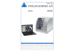
Preciso M200 Mill
Jensen Dental
50 Stillman Rd
North Haven, CT 06473
Table of Contents
Table of Contents............................................................................................................
2
1 General Information...............................................................................................................
1.1 The Manual..............................................................................................................................
1.2 Technical Data........................................................................................................................
1.3 CAM Software........................................................................................................................
1.4 Package Contents.................................................................................................................
3
3
4-5
5
6
2 Installation ................................................................................................................................
2.1 Placement...............................................................................................................................
2.2 Setting Up the Machine ......................................................................................................
2.3 Components of the Machine .............................................................................................
2.4 Compressed Air ...................................................................................................................
2.5 Dust Extraction ......................................................................................................................
2.6 Installing the CNC Application............................................................................................
7
7
7
8
9
11
12
3 Running the System ...............................................................................................................
3.1 Operation...............................................................................................................................
3.2 Safety .....................................................................................................................................
3.3 Maintenance and Cleaning.................................................................................................
13
13
14
16
4 Spindle ........................................................................................................................................ 19
4.1 High Frequency Jager Spindle............................................................................................ 19
4.2 High Frequency .................................................................................................................... 22
4.3 Tool Parameters .................................................................................................................... 22
2
General Information
Chapter 1 General Information
Read this manual carefully before connecting and starting the Preciso M200. As with all technical
systems, proper function and safety can only be guaranteed for this unit if both generally applicable
safety precautions and the specific safety information in these instructions are observed.
1.1 The Manual
This manual will enable you to properly and safely use the Preciso M200 mill and its accessories. We will
highlight specific sources of danger that may come from the Preciso M200, and emphasize the correct
use of the system. This manual should not be discarded for as long as you’re using the Preciso M200.
The Characteristics of the Preciso M200
The Preciso M200 is a desktop milling machine for dental
restorations. The compact desktop housing contains a fouraxis mechanism, a high frequency Jager Spindle, as well
as an integrated controller. The Preciso M200 is designed
to work seamlessly with Jensen authorized CAM software
packages including the Preciso and Jensen CAM’s.
The integrated high frequency Jager Spindle admits high
feed rates. Due to the precision bearing of the spindle axis,
a top surface-quality of the milled material is achieved. The
rotary axis with collet chuck is equipped with a harmonic
drive which offers highest true running accuracy for
processing restorations around their full circumference.
The automatic measurement of the rotary axis and the
automatic axis compensation ensure consistently high
precision during the milling process.
3
General Information
1.2 Technical Data
1.2.1 Basic System
•
Dimensions (W/D/H): 15.74” x 15” x 15.98”
•
Milling area illumination
•
Four- Axis Mechanism; Positioning Range
(X/Y/Z): 3.93” x 3.93” x 1.57”
•
•
Precise ball screw spindles for the 3 linear
axes with 4mm lead
•
Motor resolutions <1 um
Prepared dust extraction through
openings in the rear panel of the milling
area as well as a hose connection sleeve
and switching output at the side of the
housing (Requirements: External vacuum
cleaner)
•
Repetition accuracy +/- 0.005mm
•
•
Complete enclosing of the working area
with a closable front cover, front lid switch
and safety interlock
Under pressure sensor for monitoring the
dust extraction – milling is only possible
with activated dust extraction
•
Weight: 99.2lbs
1.2.2 Rotary Axis
•
Rotary axis free from backlash with
harmonic drive
•
Integrated frame holder for 3M ESPE
Lava™ and Jensen Materials
•
Circular spline diameter 40mm
•
6 automated tool change stations
•
Automatic measurement of rotary axis and
automatic axis compensation for highly
precise results
4
General Information
1.2.3 High Frequency Jager Spindle
• Four-axis microstep controller
• Simultaneous interpolation of 4 axes
• Micro-step operations ensures reliability
and accuracy during the milling process
• High processing speed due to
exponential acceleration ramps and
automatic change-over to full step mode
• Look-ahead feature for continuous
velocity along milling path
• Speed limitations
• Minimal feed rate: 0.3 mm/s
• Maximum feed rate: 55 mm/s
1.3 CAM Software
The Preciso M200 CAM Software is designed to make the importation of your CAD design files
effortless. For operations specific to the CAM design software, such as file importation and nesting,
please reference the software instructions for your specific CAM.
5
General Information
1.4 Package Contents
•
The Preciso M200
•
110V power supply cord
•
2 Yellow Keys for emergency release of the
front cover
•
Service unit for compressed air connection
plus 6mm hose
•
Spindle service set for collet chuck
maintenance
•
Hose connection for external vacuum cleaner
•
2.5mm hexagon socket screw key for
exchanging Frames
•
Calibration plate and measuring pin
•
Replacement tool measuring plate
•
1 pair of rubber tool changer inserts
•
1 2.8 mm drill for tool changer inserts
•
6 foot USB connection cable
•
USB dongle with CNC software
•
Preciso M200 Manual
•
Quick start manual
6
Installation
Chapter 2 Installation
2.1 Placement
The Preciso M200 requires a source of clean, dry, compressed air. The environment must be free
of dust, oil, and moisture. The surface must be sturdy and even. The room temperature should be
between 64°F and 77°F as this is the best range for the gliding lubricants used in the mill. The air
requirements are a minimum of 80 liters per minute, non-condensing.
The Preciso M200 has a voltage switching power supply. For connecting the Preciso M200, a power
supply with 80-240 VAC and 50/60 Hz is needed.
Please exercise caution and DO NOT connect the Preciso M200 to the same circuit with other,
insufficiently shielded, devices as these could electrically interfere with the mill’s controller and cause a
system failure.
2.2 Setting Up The Machine
•
Carefully open and unwrap the box and remove the foam inserts on each side of the Preciso
M200. Remove mill from box and place in predetermined location(See paragraph 2.1)
•
Connect the included service unit to your compressor using the standard compressed air
connection plug, and to the machine using the 6mm connection hose.
•
Mount the service unit at the side of the mill housing.
•
Connect the existing or providing manufacturing computer to the mill using USB cable.
•
The Preciso M200 packaged with a 6 foot USB cable. USB connections are limited in length to an
estimated 15 feet. If you plan to locate Preciso M200 within 15 feet of the controlling PC, but farther
than the provided USB cable allows, you will need to obtain a USB cable of suitable length.
•
For Ethernet connection options for distances longer than 15ft, please reference your mill quick
start guide
7
Installation
2.2 Setting Up The Machine (cont.)
•
Contact your computer supplies provider to access these items.
•
Insert the suction hose with the hose connection into the connection sleeve of the machine (See
also, Chapter 2.5)
•
Insert the dongle into a USB port of the manufacturing computer.
•
Plug the power supply cord into the machine.
•
Plug the machine power cord in a separately fused circuit current and ensure that no devices are
connected that cause heavy voltage fluctuation when switched on (air compressor, suction unit.)
!
CAUTION!
Before starting Preciso M200, make sure that the front cover is closed!
Plug the DIN4 cable for Autopower of Vacuum if your suction unit has this feature.
2.3 Components of the Machine
8
Installation
2.4 Compressed Air
The High Frequency Jager Spindle needs compressed air to operate the
pneumatic collet chuck in conjunction with automated tool changing. It
also uses the compressed air to prevent particles from getting into the
spindle. The air consumption of the machine is at a maximum of 80l/
min. The air pressure inlet connector is a style uncommon in the United
States. A 1/4” Male Threaded Coupler (shown below) may be needed
to adapt the mill fitting to your air compressor hose. These should be
readily available at your local hardware store.
Please NOTE: An Air Drier is
highly recommended
2.4.1 Compressed Air Supply
The packaging contents of the Preciso M200 include a service unit for the compressed air supply. The
integrated water separator, with its 5um superfine filter, is used to prevent air that is contaminated with
humidity, or dust particles from reaching the bearings on the spindle. It is important to note the sensitivity
of the spindle bearings. The compressor must supply dry and oil-free air according to ISO 8573-1, as
the water separator is only able to filter small amounts. Compressed air which is not dry may lead to
damage of the spindle bearings and to electrical defects.
Air purity according to ISO 8573-1:
Solid Impurities
Class 3 - Filter grade at least 5 um for solids
Water Content
Class 4 - Maximum pressure dew point +37°F
Total Oil Content
Class 5 - Maximum oil content 1 mg/m3
The compressed air connection must deliver at least 7 bar continuously
9
Installation
2.4.2 Connecting the Compressed Air
The service unit has to be mounted in an upright position directly on
the side of the mill housing. Remove the blind screws from the housing
and affix the service unit with its cylinder head screws to the machine.
Connect your compressed air supply to the service unit using a standard
compressed air connection plug. The machine will be connected via
the thin blue hose on the right side of the service unit.
2.4.3 Settings
After you have connected your compressor too the service unit, please confirm that the manometer shows
a pressure of 7 bar. If the manometer shows a pressure other than 7 bar, you must adjust the knob on the
service unit by pulling it up slightly to unlock. By turning the knob toward the “+” symbol you can increase
the pressure, turning toward the “-” symbol will decrease the pressure. Once you have completed the
adjustment of the manometer, be sure to press the knob back down to prevent any lock adjustment.
2.4.4 Maintenance
Routinely check whether liquid has accumulated in the water separator and if so, empty it by opening
the discharging screw, located at the bottom of the service unit. The condensation will be blown out
under pressure from the compressed air.
In case of dirt accumulation, the micro-filter element in the water separator must be cleaned or changed.
A clogged filter element my cause a loss of air pressure. Disconnect the air pressure by unplugging
the main compressed air supply hose. Once you disconnect the air pressure you will have the ability to
unscrew and remove the beaker. After you have unscrewed the supporting spring from under the filter
element, you can pull out the filter element. Spare parts, such as new filter elements, can be purchased
through Jensen Technical Support.
10
INSTALLATION - PRECISO
2.5 Dust Extraction
The Preciso M200 and the High Frequency Jager Spindle are prepared for dust extraction with an external
industrial vacuum cleaner or suction unit (sold separately). The machine is equipped with openings in the
rear panel of the milling area, a hose connection sleeve, and a switching output at the side of the housing.
A minimum suction power of 100 l/min and a Class M dust filter are required.
The Preciso M200 is equipped with an under pressure sensor for monitoring dust extraction. Milling
is only possible, if the dust extraction unit is switched on, and the required under pressure level has
been reached. These preventative measures are in place to prevent milling dust from entering into the
mechanics and electronics of the machine.
!
CAUTION!
•
Remember that your vacuum cleaner must be suitable for this application (micro-filter for
processing hazardous materials, etc.).
•
Empty the dust bag of the vacuum regularly, and replace the fine particle filter at regular
intervals if it’s so equipped.
In all cases, follow the instructions and safety regulations given by the manufacturer of your vacuum
cleaner.
The vacuum cleaner is connected at the side of the machine housing. An illustration of these connections
is provided in Chapter 2.3, “Setting Up The Machine”.
The machine comes with a DIN4 connection for Auto start and stop of vacuum. This connection is located
on the left side of the machine. See Chapter 2.3. The plug should be available from your vacuum supplier.
11
Installation
2.6 Installing the CNC Application
•
Connect and start your manufacturing computer
•
Insert the dongle into the USB port of this computer
•
Start setup.exe and follow the instructions in the installation program
•
For additional information, please reference your CAM software manual
For additional information, please reference the Software Manual
!
CAUTION!
•
Installing and operating the software and the Preciso M200 is only possible with
the CNC Dongle, which is separate from your CAM application.
•
Please contact Jensen Technical Support to install the CAM software on your PC, if
it has not been installed already.
•
For additional information, please visit www.PrecisoEducation.com
12
Running The System
Chapter 3 - Running The System
3.1 Operation
After you have ensured that all cables have been connected and
the front cover is closed, you can turn on the Preciso M200 by using
the power switch on the left side of the housing.
The Preciso M200 machine is equipped with a safety contact and
safety interlock at the front cover. During milling, the front cover
must remain closed.
The Preciso M200 front cover comes locked. Before proceeding,
you will need to unlock. Remove the blind plug at the left side of
the housing, unlock the door by turning the Yellow Emergency Key
counterclockwise. Now you can open the front cover. Reattach the
blind plug.
The Preciso M200 is already calibrated on delivery. As long as your
milling results are correct, there is no need for a further calibration. If
your results should become inaccurate, a calibration could become
necessary. In such a case, please contact a Jensen Technical Support
Team for remote assistance at 800-528-5531 before recalibrating the
machine.
13
Running The System
3.2 Safety
3.2.1 Intended Use of The Preciso M200
The Preciso M200 has been designed for milling crown and bridge restorations, inlays, onlays, and
veneers. The Preciso M200 is calibrated and warrantied for processing zirconia, wax, nanocomposites,
and most synthetic plastics (e.g. PMMA) It is important to note that you should NOT use too high values
for the cutting depth and the rate of feed. Doing so could lead to the work piece ripping loose or the
tool becoming jammed. This can cause irreversible damage to the machine and/or the high frequency
Jager Spindle. By using the Preciso CAM Software, the software automatically calculates the optimal
parameters.
3.2.2 Safety and Protective Regulations
All operators of the Preciso M200 must be trained in the proper handling of the machine and in the
following safety and protective regulations.
•
The working place must be kept clean and orderly. A clean and orderly working environment will
help to minimize accidents.
•
Keep children and animals away from the Preciso M200
•
Only mill with activated dust extraction. Please keep in mind that your vacuum cleaner must be
suitable for this application (micro-filter for processing zirconium).
•
The Preciso M200 must be operated with the front door closed.
•
Before starting to work with the Preciso M200, check for possible damage. Ensure that all safety
devices and their components are in place and in good working order. Damaged safety devices or
parts thereof must, if not stated otherwise in the User Manual, be repaired or replaced by authorized
service personnel. Contact Jensen Technical Support at 800-528-5531.
•
While working with the Preciso M200 in maintenance mode or when the front door is open, the
operator, and all persons within reach of the machine, must wear protective safety glasses.
14
Running The System
•
Do not let the machine run unobserved.
•
If using external CAM software, loud noises may occur from certain modes of work. All persons
within reach of the machine must wear ear protection. Loud noise is often a sign for inappropriate
operating circumstances. Ensure that the work piece is fixed properly and check the values for
rotational speed, cutting depth, feed rate, tool endurance and the material.
•
The safety devices of the machine are designed for practical use. It is prohibited to circumvent or
tamper with any preset safety devices or settings.
•
It is imperative to confirm that the tools are loaded straight in the changing station and that they are
placed in the positions indicated in the manufacturing software.
•
A damaged cable must be removed from operation. An original spare cable must be used to
replace it. To order additional spare cables, please contact the Jensen Dental Technical Support
Team, 800-528-5531.
3.2.2.1 High Frequency Jager Spindle
For operation and maintenance of the high frequency Jager Spindle, follow the below guidelines to
prevent accidents. Improper handling or operations differing from the intended use of the machine
greatly diminish the safety to the operator, and the safe operations of the machine.
•
Do not use unbalanced tools at high rotational speeds. This applies to the single tooth cutters and
engravers. Such an imbalance will generate loud running noise and will put a strain on the ball
bearing of the spindle.
•
Do not use tools with cutting edge diameters that exceed the shank diameter.
•
Please be aware of the information about the choice of tools and adjustment of tool parameters
outlined in Chapter 4.2.2.
!
CAUTION!
While working in maintenance mode, do not put your hand into the range of
the rotating tools.
15
Running The System
3.2.2.2 Fixing Devices
•
Always ensure and check that the tool and frames are tightly fastened before starting to mill. Due
to the high forces that act on the frame, improperly fixed rods and frames may loosen.
•
In general, you should start with a relatively small cutting depth and increase it in small steps. A
higher abrasive rate in milling works, lead to stronger forces acting on the work piece. If these
forces exceed the fixing power of the fastening device, the work piece may come loose.
3.3 Maintenance and Cleaning
3.3.1 Collet Chuck
It is important to clean the collet chuck of the machining spindle once a week and heed follow the
instruction provided in Chapter 4: Spindle.
3.3.2 Fixing Device
It is important to clean the frame holder at regular intervals with a soft brush and a vacuum cleaner.
3.3.3 Calibration
The machine is already calibrated on delivery. As long as your milling results are accurate, there is no
need for additional calibration. If your milling should become inaccurate, a calibration could become
necessary. If a recalibration becomes necessary, please contact the Jensen Dental Technical Support
Team, 800-528-5531, for assistance.
16
Running The System
3.3.4 Measuring Key
•
The measuring key is a consumable item. Wear is caused by
the contact between the tool and measuring key, and effects an
indentation in the aluminum. The deeper the indentation, the
greater the length (L) of different tools.
•
Due to dust and chipping on the measuring key, the spindle needs
to apply force until the electrical contact between the tool and the
measuring key is established.
•
Keep the measuring key clean to minimize wear. It is sufficient to wipe
the measuring key once with your finger before starting a milling
job.
•
It is important to ensure that the measuring key is always kept
clean and that the electrical contact for the tool length detection is
possible.
•
For restoring the measuring key, please contact the Jensen Dental
Technical Support Team at 800-528-5531.
3.3.5 Internal Cleaning
Clean the machine daily to prevent dust and chips from accumulating in the guiding rails and other
sensitive components of the system as well as the vacuum dust collection chamber and inside of the
front cover. Do not use compressed air for this, as air can blow the dust into the guiding rails. Use a
vacuum cleaner to remove all dust. In addition, please check the air filter for moisture.
17
Running The System
3.3.6 External Cleaning (Housing)
•
The cleaning of powder-coated surfaces should generally be done with a soft dry cloth.
•
If dirt cannot be removed with a soft dry cloth, the cloth can be moistened. If necessary, a
PH-neutral cleaner can be used.
•
Any contact between the powder coatings and alkaline or acid substances must be avoided.
These will damage the housing of the machine.
•
If the use of a special cleaner is necessary, it is recommended to test the cleaner on a small
surface area of the housing first.
•
Please pay special attention to the affixed machine labels. They are especially sensitive to
intensive rubbing and harsh detergents will make them peel off.
3.3.7 Additional Preventative Maintenance
Wires and Electircal Plug Connections:
Description:
Check for loose wires and reset all electrical plug connections. (Requires
removal of outside housing.)
Tool:
4 mm Hex wrench
Duration:
5 minutes
Frequency:
Every 12 months or 1200 hours
18
Spindle
Chapter 4 Spindle
4.1 High Frequency Jager Spindle
4.1.1 Features
•
Nominal power under continuous load (S1): 170 Watt
•
Maximal power (P maximum): 240 Watt
•
Rotational speed range: 5,000 – 60,000 RPM
•
Collet chuck 3mm
•
Precision shaft with double bearing
•
Quick chucking device for manual tool change
!
CAUTION!
The high frequency Jager Spindle is a high precision device
that should never be subject to any unnecessary movement.
4.1.2 Manual Tool Change
Manual tool change is done through the control software. Please note
that only Jensen authorized tools may be used in your M200.
Procedure:
•
Start the control software and choose the control panel. In order to
execute a manual tool change, click on the Spindle Maintenance
button. The spindle will move into a position that is easily
accessible.
•
The system will prompt you about opening collet, click ok. If
system doesn’t open collet click on the collet chuck button to
open.
•
Place tool in collet and click collet chuck button again to close.
19
Spindle
4.1.3 Maintenance and Cleaning
To guarantee a safe and precise operation of the high frequency Jager Spindle, the collet chuck has to be
cleaned regularly. No grease or oil may enter inside the collet chuck. The inside cone of the spindle shaft,
collet and the tool shafts must be free from oil, grease and dust to ensure optimal tension force.
DO NOT use compressed air to clean the spindle, as dust could be blown into the sensitive bearing area.
Tool:
Clean and soft cloth, soft brush, spindle maintenance set
Duration:
Approximately 5 minutes
Frequency:
Once a week
20
Spindle
Spindle Maintenance Procedure:
•
Start the control software (CNC) and choose the control panel. In order to execute spindle
maintenance, click on the Spindle Maintenance button. The spindle will then move into a
position that is easily accessible.
• In order to unscrew the collet chuck, place the calibration tool
inside collet then the collet wrench over the collet. It is a round
tool with a Hex hole in the middle. Next, turn the collet wrench
clockwise to unscrew the collet chuck completely.
• Clean the internal cone of the shaft with the felt cone of the
maintenance set. The internal cone must be free of dirt.
• Clean the collet chuck with a clean, soft, round brush, preferably
the soft brush from the spindle maintenance set.
• After cleaning, apply a light grease film on the taper area of
the collet chuck.
!
CAUTION!
Use caution to ensure that no grease or oil enter inside the collet chuck.
•
Reinsert the collet chuck and tighten it hand tight. Use same tools as for removal.
•
Weekly, or every 40 hours, maintenance is required for the collet chuck to ensure proper
function of the Preciso M200.
!
CAUTION!
Grease only the outside of the collet and use only the grease provided in the
service kit. No other grease or oil should be used, and only the outside of the
collet should receive grease.
21
Spindle
4.2 High Frequency
4.2.1 Automatic Tool Change
Tool changes are carried out automatically using the mill’s 6 tool magazine. A frequency converter is
integrated in the CAM Impression thus, all spindle features are controlled by the production software.
Only tools with a shank diameter of 3mm should be used. The cutting edge diameter may be 3mm
maximum.
Tool Dimensions:
For storing the tool in the tool changing station, a 3mm shank with a length of at least 6mm is required.
All tools should have a stop ring installed on shank.
!
CAUTION!
Install only retaining rings according to DIN 471-A3.
4.3 Tool Parameters
In the Preciso M200 CAM software, all processing and tool parameters are already preset. Jensen
reserves the right to void your warranty on the mill and materials used if you use another CAM software.
It is important to follow all safety and protective regulations outlined in this manual.
22
Get a Team Preciso support strategy customized for you
by calling 1.800.243.2000 or visit precisodental.com
800-243-2000
REV 0
www.jensendental.com