1
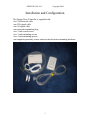
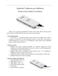
housEvolve
Garage Door Controller
User Manual and Installation Guide
FREEVOLVE® LLC
Copyright 2008
Introduction
Thank you for purchasing a FREEVOLVE® product. We designed it to
provide you with years of reliable service.
The following setup instructions will help you get up and running quickly.
While we hope all our products are self-explanatory, the enclosed user guide
should cover all questions you may have. Please refer to the “Support”
section of our website – www.freevolve.com – for additional information.
Warranty Information
All FREEVOLVE® products are covered against manufacturing defects for
a period of 2 years from the date of purchase. During the warranty period we
will replace any defective unit free of charge.
The warranty does not cover any problem caused by accident; abuse;
neglect; improper installation, operation or modification; any misuse
contrary to the instructions in this user guide.
2
FREEVOLVE® LLC
Copyright 2008
Installation and Configuration
The Garage Door Controller is supplied with:
-two 25ft network cable
-one 25ft signal cable
-one 3ft signal cable
-one network termination plug
-two 3-inch wood screws
-two 1-inch mounting screws
-two 2-inch mounting spacers
-one magnetic proximity sensor and associated actuator mounting hardware.
3
FREEVOLVE® LLC
Copyright 2008
1. Installation
• We recommend that this installation be performed by a
qualified person.
The housEvolve Garage Door Controller was designed to be
compatible with all garage door opener brands.
• Unplug your garage door opener.
• Open the cover of your housEvolve Garage Door Controller by
removing the 4 retaining screws. Note the location of two
mounting holes as shown below:
4
FREEVOLVE® LLC
Copyright 2008
• The Garage Door Controller can be mounted on any accessible
location (wall, ceiling, etc). In this example we decided to
attach the Garage Door Controller directly to the case of the
Garage Door Opener. For this, one of the Garage Door Opener
case screws was removed and then re-attached through one of
the Garage Door Controller mounting holes:
• Replace the cover to the Garage Door Controller
• Door proximity detector: The Garage Door Controller relies on
information provided by the proximity detector to rely door
position information to the Main Controller (Door Open/Door
5
FREEVOLVE® LLC
Copyright 2008
Closed). The image below shows the two proximity sensor
elements:
i. The Contact element, identified by the presence of two
screw-type wire terminals
ii. The magnetic element, identified by the absence of any
terminals
• The Magnetic Element must be mounted somewhere on the
Garage Door and the Contact Element must be mounted
somewhere on the Garage Door so that:
i. The Magnetic Element must be parallel with and at a
distance of less than 1.5in from the Contact Element
when the Garage Door is closed
ii. The Proximity Sensor must not obstruct the garage door
movement in any way
6
FREEVOLVE® LLC
Copyright 2008
• In this installation example, the Contact Element is mounted
above the garage door (on the door frame), at a height that
ensures unobstructed door motion (the garage door’s tracks
begin pulling the door away from the frame by the time the top
edge of the door becomes parallel to the Contact Element). The
Magnetic Element is mounted on the top edge of the door, at a
height that places it within the required distance and alignment
of the Contact Element when the door is fully closed:
• If your Garage Door Controller Module is equipped with the
optional Access Keypad Module (see below), please follow the
next steps to install it:
7
FREEVOLVE® LLC
Copyright 2008
• 1. Using a 5/8” wood bit, drill a hole through the side of the
garage door frame at the desired height at which the Access
Keypad Module will be mounted (enclosure center).
• 2. Feed the end of one of the 25ft network cables provided
through this hole so that about a 6in length of cable is available
on the outside of the garage door frame.
8
FREEVOLVE® LLC
Copyright 2008
• 3. Open the cover of the Access Keypad Module by removing
the 4 retaining screws. Note the position of the keypad ribbon
cable inside and the two mounting holes:
• 4. Disconnect the Keypad Ribbon Cable from the Access
Keypad Module’s Circuit Board. Feed the protruding network
cable through the Network Cable Access hole and mount the
device to the Garage Door Frame.
9
FREEVOLVE® LLC
Copyright 2008
• 5. Connect the network cable to the Circuit board and pull the
excess cable back through the door frame.
• 6. Re-connect the ribbon cable to the Circuit Board
10
FREEVOLVE® LLC
Copyright 2008
• 7. Carefully replace the Access Keypad Module Cover and the
four mounting screws.
• Connect the Access Keypad Module Network Cable to the
“KEYPAD” port on the Garage Door Controller. Any excess
cable length should be coiled and tied to one of the support
arms of the Garage Door Opener. Ensure the cable is clear of
the drive chain.
• Connect the 25ft signal cable provided to the “SENSOR” port
of the Garage Door Controller using the pre-attached connector.
Run this cable to the Contact Element of the proximity sensor.
Cut off or coil any excess cable, strip about 0.5” of wire on
each conductor and connect the cable to the Contact Element of
the proximity sensor.
• If the Garage Door Controller is part of a housEvolve system,
use the second Network Cable provided to connect one of the
“SYSTEM” ports to the housEvolve network. The remaining
“SYSTEM” port should be connected to the Network
Termination Plug provided or to another housEvolve
component.
• Trace the cable connecting your Garage Door Opener to the
Door Open/Close button. Note the two terminals where this
cable connects to your Garage Door Opener. Connect the 3ft
11
FREEVOLVE® LLC
Copyright 2008
signal cable provided to the “DOOR” port of the Garage Door
Controller using the pre-attached connector. Run this cable to
the Garage Door Opener terminals identified above. Cut off or
coil any excess cable length, strip off about 1” of wire on each
of the two conductors and connect each one to one of the Door
Button terminals:
12
FREEVOLVE® LLC
Copyright 2008
Here is the installed Garage Door Controller:
2. Testing the Garage Controller Installation
Power up the Garage Door Controller by connecting it to an active
housEvolve network. The yellow light next to the SYSTEM ports should be
ON, (indicating network power). The green light next to the SYSTEM ports
will blink about once a second. If the device is a stand-alone installation, use
the enclosed 15V DC adapter. Note that the SYSTEM lights will be off
because there is no network connection detected.
Manually close the Garage Door. The proximity sensor should engage and
the green light next to the SENSOR port should be ON. If the Sensor light is
not ON, check
that the Garage Door Controller is powered
that the Magnetic and Contact Elements of the proximity sensor
parallel and within 1.5in of each other
13
FREEVOLVE® LLC
-
Copyright 2008
the connections at both ends of the sensor cable
If installed, check the Access Keypad Module. The yellow light should be
blinking (if no password is defined) or the green light should be ON (if
password is defined).
14