1
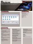
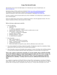
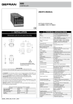
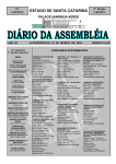
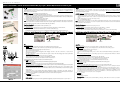
CAREL code +050000930 - rel. 1.1 dated 25/07/06 pCOnet PCO1000BA0 - Scheda di interfaccia BACnet MS/TP per pCO / BACnet MS/TP interface board for pCO Fig. 1 Fig. 2 La scheda opzionale pCOnet (codice PCO1000BA0) per controllori pCO Sistema permette il collegamento di un pCO* ad una rete di tipo BACnet MS/TP (Master/Slave Token pass). La connessione RS485 è optoisolata rispetto al controllore pCO*. Nota: pCOnet non è compatibile con la serie pCOB*. pCOnet è di tipo Master/Slave. The optional pCOnet board (code PCO1000BA0) for pCO sistema controllers allows the pCO* to be connected to a BACnet MS/TP network (Master/Slave Token pass). The RS485 connection is optoisolated compared with pCO*. Note: pCOnet is not compatible with the pCOB* series. pCOnet features Master/Slave operation. Installazione Figg. 2, 3, 5: per installare pCOnet nel controllore pCO*: 1. Disinserire l’alimentazione pCO e togliere lo sportellino “Serial Card” del pCO* (Fig. 2); 2. inserire pCOnet nel corrispondente connettore a pettine interno, assicurandosi che sia ben inserita e a contatto con i due appoggi del pCO*. Poiché lo spazio è esiguo, l’inserimento di pCOnet e l’accoppiamento dei connettori può risultare difficoltoso: inserire pCOnet obliquamente e farla poi ruotare fino a far combaciare i connettori; 3. inserire gli opportuni ponticelli (per il significato si veda più avanti); 4. inserire lo sportellino di chiusura fornito in dotazione a pCOnet. Nota: se il dispositivo utilizzato per la lettura dei dati dalla rete 485 è connesso a terra e l’eventuale convertitore RS232-RS485 o la seriale RS485 dello stesso dispositivo hanno un isolamento funzionale minore di 2kV è necessario collegare il connettore G0 della scheda pCOx a terra. Non è possibile installare la scheda a diretto contatto con il pannello metallico del quadro elettrico. Installation Figs. 2, 3, 5: to install pCOnet in the pCO* controller: 1. Disconnect the power supply from the pCO* and remove the “Serial Card” cover (Fig. 2); 2. insert pCOnet in the plug-in connector, making sure that it is fully inserted and in contact with the two supports on the pCO*. As there is little space available, this operation may be complex: as a result, insert the pCOnet at an angle and then tilt it back until the connectors line up; 3. insert the required jumpers (see below for the meanings of these); 4. fit the cover supplied with the pCOnet. Nota: if the device used to read the data from the 485 network is earthed and the RS232-RS485 converter or the RS485 serial port on the device have functional insulation of less than 2kV, connector G0 on the pCOx board must be earthed. The board cannot be installed in direct contact with the metal panel on the electrical panel. Significato dei ponticelli Meaning of the jumpers All’interno dell’apertura frontale dello sportellino si trovano i ponticelli P1, P2, P3. Con riferimento alla fig. 4: - il ponticello P1 inserisce una resistenza da 510 ohm di polarizzazione tra la linea dati negativa (-) e il riferimento GND; - il ponticello P2 inserisce una resistenza di terminazione da 120 ohm tra le due linee dati (+) e (-); - il ponticello P3 inserisce una resistenza da 510 ohm di polarizzazione tra la linea dati positiva (+) e la tensione interna +5 Vdc. Jumpers P1, P2 and P3 are located inside the front opening of the cover. With reference to Fig. 4: - jumper P1 adds a 510 ohm polarisation resistance between the negative data line (-) and GND; - jumper P2 adds a 120 ohm terminal resistance between the two data lines (+) and (-); - jumper P3 adds a 510 ohm polarisation resistance between the positive data line (+) and the +5 Vdc internal voltage. Inserire tutti e tre i ponticelli sulla unità ad inizio rete e su quella a fine rete. Non inserire ponticelli sulle unità intermedie. Per rispettare le normative europee EMC di prodotto, è necessario aggiungere al cavo di rete la ferrite in dotazione come illustrato in Fig. 5. Insert all three jumpers on the unit at the start of network and the unit at the end of the network. Do not insert the jumpers on the intermediate units. For compliance of the product with the European EMC standards, add the ferrite supplied to the network cable, as illustrated in Fig. 5. Status LED RS485 LED RS485 LED Fig. 6 Fig. 5 Fig. 3 Uso Con riferimento alla fig. 6: Il LED Status (sinistra) indica lo stato della comunicazione con il controllore e anche lo stato di pCOnet. Sequenza di avvio: all’accensione, o dopo un riavvio di pCOnet, il LED Status esegue la seguente sequenza: -spento per 2 secondi; -dopo 2 secondi dal riavvio: rapido lampeggio rosso-verde-rosso-verde…; -dopo 5 secondi dal riavvio: verde fisso; -dopo circa 50 secondi dal riavvio: lampeggiante (colore lampeggio: vedi sotto - Stato della comunicazione con pCO*) inizia la comunicazione pCOnet-pCO*. Stato della comunicazione con pCO*: una volta conclusa la sequenza di avvio, il LED Status lampeggia per indicare la qualità della comunicazione con pCO*: -rapido verde-buio-verde se la comunicazione con pCO* è ok (pCO* ON-LINE); -lento rosso-buio-rosso se la comunicazione con pCO* non è stabilita (pCO* OFF-LINE) -verde-rosso-verde se pCOnet rileva errori o temporanea mancanza di risposta da pCO*. Fig. 4 Il LED RS485 (destra) indica lo stato della comunicazione con la rete BACnet MS/TP (485). Il LED assume i seguenti stati: Sequenza di avvio: all’accensione o dopo un riavvio di pCOnet il LED RS485 esegue la seguente sequenza: -spento per circa 50 secondi; -dopo circa 50 secondi dal riavvio di pCOnet: verde–rosso–verde–rosso lentamente: al termine BACnet risulterà attivo. Stato della comunicazione con rete BACnet MS/TP: una volta conclusa la sequenza di avvio, il LED RS485 lampeggia per indicare la qualità della comunicazione con la rete BACnet MS/TP: -verde con occasionali lampeggi rossi se la comunicazione è ok (significato BACnet MS/TP: verde acceso = pCOnet detiene il Token (controllo della rete MS/TP); verde spento = pCOnet NON detiene il Token; rosso acceso = Poll-For-Master, ricerca di un Master a cui poter passare il Token); -contemporaneo verde e rosso (significato BACnet MS/TP: Poll-For-Master continuo): comunicazione non stabilita (problemi di connessione, o nessun dispositivo di rete trovato); questo potrebbe dipendere da difficoltà di connessione elettrica oppure da impostazioni di comunicazione non compatibili con gli altri dispositivi di rete connessi. Si veda la sezione Configurazione. Il tasto Pushbutton permette di : - riavviare pCOnet - richiamare la configurazione di fabbrica. Tool BACset - Fig. 7 Fig. 6 Pushbutton Riavvio di pCOnet Da scheda accesa e a regime (quindi con LED Status regolarmente lampeggiante), tenere premuto il tasto per più di 5 s e per non più di 10 s. Fig. 5 Pushbutton Operation With reference to Fig. 6: The Status LED (left) indicates the status of communication with the controller and the status of the pCOnet. Starting sequence: on power-up, or after restarting pCOnet, the Status LED switches in the following sequence: -OFF for 2 seconds; -2 seconds after restarting: quick flash red-green-red-green…; -5 seconds after restarting: green on steady; -around 50 seconds after restarting: flashing (colour: see below - Status of communication with the pCO*) pCOnet-pCO* communication starts. Status of communication with the pCO*: once the starting sequence has been completed, the Status LED flashes to indicate the quality of communication with the pCO*: -quick green-OFF-green if communication with the pCO* is OK (pCO* ON-LINE); -slow red-OFF-red if communication has not been established with the pCO* (pCO* OFF-LINE) -green-red-green if pCOnet detects errors or a temporary lack of response from the pCO*. The RS485 LED (right) indicates the status of communication with the BACnet MS/TP network (RS485). The LED shows the following information: Starting sequence: on power-up or after rebooting pCOnet, the RS485 LED switches in the following sequence: -off for around 50 seconds; -around 50 seconds after restarting pCOnet: slow green–red–green–red: at the end, BACnet will be active. Status of communication with the BACnet MS/TP network: once the starting sequence has been completed, the RS485 LED flashes to indicate the quality of communication with the BACnet MS/TP network: -green with occasional red flashes if communication is OK (BACnet MS/TP meaning: green ON = pCOnet keeps the Token (control of the MS/TP network); green OFF = pCOnet DOES NOT keep the Token; red on = Poll-For-Master, search for a Master to pass the Token to); -green and red ON together (BACnet MS/TP meaning: continuous Poll-For-Master): communication not established (connection problems, or no network device found); this may depend on electrical connection difficulties or communication settings that are not compatible with the other network devices connected. See the section on Configuration. The Pushbutton is used to : - restart pCOnet - recall the factory configuration. Restarting pCOnet With the board on and in stable operation (Status LED flashing continuously), hold the button for more than 5 seconds and no more than 10 seconds. CARATTERISTICHE GENERAL/ GENERAL SPECIFICATIONS Interfaccia RS485: isolamento funzionale 630 Vac. RS485 interface: functional insulation 630 Vac. Protocolli gestiti/Protocols managed: BACnet MS/TP. Baud rate MS/TP selezionabili:/Settable MS/TP baud rate: 76800, 38400 (default), 19200, 9600 Memoria/Memory: 16MB RAM, 8 MB Flash. CPU: ARM7 TDMI@74 MHz Sistema operativo/Operating system: LINUX 2.4.21. Tool di configurazione /Configuration tool: BACset Condizioni di funzionamento: 0T55 °C, 20…80% U.R. non cond.; Operating conditions: 0T55 °C, 20 to 80% RH non-cond.; Condizioni di immagazzinamento: -20T70 °C, 20…80% U.R. non cond.; Storage conditions: -20T70 °C, 20 to 80% RH non-cond.; Grado di inquinamento ambientale: 2 Environmental pollution: 2. Tensione nominale di alimentazione: 8…38Vdc Power suppìy rated voltage : 8…38Vdc Massima potenza assorbita: 1W Maximum power absorbed : 1W Precauzioni nel maneggiare il prodotto. I danneggiamenti elettrici che si verificano sui componenti elettronici avvengono quasi sempre a causa delle scariche elettrostatiche indotte dall’operatore. È quindi necessario prendere adeguati accorgimenti per queste categorie di componenti, ed in particolare: • prima di maneggiare qualsiasi componente elettronico o scheda, toccare una messa a terra (il fatto stesso di evitare di toccare un componente non è sufficiente in quanto una scarica di 10000 V, tensione molto facile da raggiungere con l’elettricità statica, innesca un arco di circa 1 cm); • i materiali devono rimanere per quanto possibile all’interno delle loro confezioni originali. Se necessario, prelevare la scheda da una confezione e trasferire il prodotto in un imballo antistatico senza toccare con le mani i lati della scheda su cui sono montati i componenti elettronici; • evitare nel modo più assoluto di utilizzare sacchetti in plastica, polistirolo o spugne non antistatiche; • evitare nel modo più assoluto il passaggio diretto tra operatori per evitare fenomeni di induzione elettrostatica e conseguenti scariche; servirsi di un tavolo di passaggio. Dopo circa altri 10 secondi dal rilascio del tasto, il LED Status smetterà di lampeggiare, e dopo altri 15 secondi pCOnet si riavvia: LED Status rapidamente lampeggiante rosso-verde-rosso-verde… Richiamo della configurazione di fabbrica (modalità “factory bootswitch”) Recalling the factory configuration ( “factory bootswitch” mode) Con la seguente procedura pCOnet utilizzerà i parametri di fabbrica invece di quelli specificati dall’utilizzatore. Consultare la tabella dei parametri e dei valori di fabbrica nella sezione Configurazione. In modalità “factory bootswitch” pCOnet non memorizza i valori richiamati, per cui al successivo riavvio senza pressione del pulsante, pCOnet utilizzerà di nuovo i valori impostati dall’utilizzatore. All’acquisto di pCOnet i parametri utilizzatore risultano impostati con valori uguali a quelli della configurazione di fabbrica. Da pCOnet spenta: - accendere pCOnet (accendere perciò il controllore pCO* con pCOnet già inserita) mantenendo premuto il pulsantino a lungo finchè il LED status lampeggerà LENTAMENTE 3 volte rosso-buio; - lasciare il tasto mentre il LED sta lampeggiando: dopo aver concluso i 3 lampeggi rossi il LED diventa verde; poi il LED conferma il riconoscimento del rilascio del tasto lampeggiando RAPIDAMENTE 3 volte rosso-buio, quindi diventa di nuovo verde. Per il completo avvio di pCOnet saranno necessari circa altri 40 secondi fino ad ottenere il LED RS485 lampeggiante; solo da questo momento in poi sarà possibile accedere da remoto a pCOnet. Da pCOnet già accesa: - riavviare pCOnet (vedi sopra: Riavvio di pCOnet); - dopo il riavvio, procedere come da pCOnet spenta (vedi sopra). With the following procedure pCOnet uses the default parameters instead of the ones specified by the user. See the table of parameters and factory values in the section on Configuration. In “factory bootswitch” mode, pCOnet does not save the recalled values, and consequently when next restarted without pressing the button, pCOnet will again load the user settings. When purchasing pCOnet the user parameters are set to the factory configuration values. With pCOnet OFF: - switch pCOnet on (i.e. switch on the pCO* controller with the pCOnet board inserted) by pressing and holding the button for at least 20 seconds: the Status LED will flash SLOWLY 3 times, red-off; - release the button while the LED is flashing: after 3 red flashes, the LED comes on green; the LED then confirms recognition of the button by flashing QUICKLY 3 times red-off, and then comes on green again. Complete start-up of the pCOnet will take another 40 seconds, then the RS485 LED starts flashing; only from this moment on can pCOnet be accessed via a remote connection. With pCOnet already ON: - restart pCOnet (see above: Restarting pCOnet); - after the restart procedure, follow the steps described above for pCOnet OFF. Documentazione Documents Nel sito ksa.carel.com sono disponibili delle Application Notes relative al protocollo BACnet di pCOnet, PICs (Protocol Implementation Conformance Statement) e al tool di configurazione BACset. Application Notes relating to the pCOnet BACnet protocol, PICs (Protocol Implementation Conformance Statement) and the BACset configuration tool are available at ksa.carel.com. Configurazione (Fig. 7) Configuration (Fig. 7) Procedura di configurazione dei parametri di pCOnet per una corretta comunicazione in una rete MS/TP: - collegare pCOnet via 485 ad un Computer (è necessario un convertitore per reti 485; nella fase di configurazione è possibile ad esempio utilizzare il prodotto CAREL CVSTDUMOR0 per porta USB. si sconsiglia l’utilizzo di convertitori USB nell’impianto per il grosso carico di dati trasmessi in una rete BACnet™ complessa). - Installare il tool di configurazione CAREL “BACset” disponibile gratuitamente sul sito ksa.carel.com. Attenzione: se i valori dei parametri di pCOnet non sono adatti, la comunicazione con BACset può risultare impossibile. Per potersi collegare a pCOnet è necessario allora riaccendere o riavviare pCOnet utilizzando i parametri di fabbrica “factory bootswitch” (si veda la sezione Uso - Pushbutton). Procedure for configuring the pCOnet parameters for correct communication over an MS/TP network: - connect pCOnet via RS485 to a computer: during configuration, the CAREL product code CVSTDUMOR0 for USB ports can be used. USB converters should not be used in the installation due to the large volume of data transmitted across a complex BACnet™ network. - Install the CAREL “BACset” configuration tool, available free-of-charge at ksa.carel.com. Important: if the values of the pCOnet parameters are not suitable, communication with BACset may not be possible. To connect to pCOnet, restart pCOnet using “factory bootswitch” mode (see the section on Operation - Pushbutton). Parametro Device instance Station Address MaxMaster Max Info Frames BaudRate Min Max 0 4194303 0 127 0 127 0 255 9600-19200-38400-76800 Factory 77000 0 127 20 38400 Note utilizzatore Significato dei parametri. Device Instance: Station Address: Max Info Frames: MaxMaster: Precautions when handling the product. Electrical damage on electronic components usually occurs because of electrostatic discharges caused by the operator. Suitable precautions must be therefore be taken when handling these components, specifically: • before handling any controller, earth yourself (not touching the board does not prevent a spike, as a 10000V discharge, easily reached with static electricity, can produce an arc of about 1 cm); • all materials must be kept inside their original package as long as possible. If necessary, take the controller from its package and place it into an antistatic package without touching the side of the board containing the electronic components with your hands; • absolutely avoid non-antistatic plastic bags, polystyrene or sponges; • do not pass the controller directly to other operators (to prevent from electrostatic induction and discharges); use a work bench. Around 10 seconds after releasing the button, the Status LED will stop flashing, and 15 seconds later pCOnet will be restarted: Status LED quickly flashing red-green-red-green… Baud Rate: è un numero che identifica in modo univoco un dispositivo all’interno della rete BACnet (la rete BACnet può essere composta anche da dispositivi BACnet di tipo non MS/TP). Se due unità hanno lo stesso Device Instance verranno generati errori di identificazione. (indirizzo di stazione) è un numero che differenzia tra loro le unità nella rete BACnet MS/TP. Se due unità hanno lo stesso Station Address verranno generati errori di identificazione. Per abbreviare il tempo di scambio dati tra i Master, è consigliabile che gli Station Address delle unità Master inizino da 0 e proseguano senza saltare alcun numero. stabilisce il numero massimo di pacchetti di informazioni scambiati superato il quale l’unità Master cederà il controllo (Token) della rete ad un’altra unità Master. Stabilisce indirettamente una priorità tra i Master nell’utilizzo della rete: numeri elevati garantiscono ad un Master uno scambio dati più consistente. per abbreviare il tempo di scambio dati tra i Master, si consiglia di impostare MaxMaster eguale allo Station Address del Master avente Station Address più alto. Infatti ogni Master, dopo aver utilizzato la rete, ne cede il controllo al Master successivo. Con il parametro MaxMaster si specifica a pCOnet l’indirizzo del Master di rete che ha Station Address più alto: grazie a questo parametro pCOnet saprà che non esiste alcun altro Master con Station Address più alto di MaxMaster; pCOnet cederà quindi il controllo della rete al Master successivo ma comunque non oltre MaxMaster; se non trova alcun Master successivo farà subito ricominciare il ciclo cedendo il controllo al Master con Station Address più basso. velocità di transito dati. Il Baud Rate deve essere unico per tutti i dispositivi connessi, altrimenti lo scambio dati produrrà errori di comunicazione. Per reti lunghe sono più adatti Baud Rate bassi che garantiscono una quantità minore di errori di comunicazione. Nel caso si utilizzi Baud Rate=76800 assicurarsi che il dispositivo supporti questa velocità di comunicazione. Questo baud rate non è supportato dalle seriali RS232 dei normali pc. Tutti i marchi registrati sono proprietà dei rispettivi titolari. Parameter Device instance Station Address MaxMaster Max Info Frames BaudRate Min Max 0 4194303 0 127 0 127 0 255 9600-19200-38400-76800 Factory 77000 0 127 20 38400 User notes Meaning of the parameters. Device Instance: Station Address: Max Info Frames: MaxMaster: BaudRate: this is a number that uniquely identifies a device inside the BACnet network (the BACnet network can also include non-MS/TP BACnet devices). If two units have the same Device Instance, identification errors will be generated. this is a number that differentiates the units in the BACnet MS/TP network. If two units have the same Station Address, identification errors will be generated. To speed up the data exchange between the Master units, the Station Address of the Master units should start from 0 and continue without skipping any numbers. this establishes the maximum number of information packages exchanged, above which the Master unit will give up control (Token) of the network to another Master unit. It thus indirectly establishes a sort of priority between the Master units in the network: high numbers guarantee the Master a higher data exchange volume. to speed up data exchange between the Master units, MaxMaster should be set to the Station Address of the Master with the highest Station Address. In fact, each Master, after having used the network, passes over control to the next Master. The MaxMaster parameter specifies to pCOnet the address of the network Master with the highest Station Address: using this parameter, pCOnet will know that there is no other Master with a higher Station Address than MaxMaster; pCOnet will then give control of the network to the next Master, however not beyond MaxMaster; if no next Master is found, the cycle will begin again, with control being given to the Master with the lowest Station Address. data transfer speed. The BaudRate must be the same for all the devices connected, otherwise the exchange of data will generate communication errors. For extended networks, low baud rates should be specified, as this guarantees less communication errors. If Baud Rate=76800, make sure that the device supports this communication speed. This baud rate is not supported by the RS232 serial port on a normal PC. All registered trademarks are the property of their respective owners. AVVERTENZE IMPORTANTI Il prodotto CAREL è un prodotto avanzato, il cui funzionamento è specificato nella documentazione tecnica fornita col prodotto o scaricabile, anche anteriormente all’acquisto, dal sito internet www.Carel.com. Il cliente (costruttore, progettista o installatore dell’equipaggiamento finale) si assume ogni responsabilità e rischio in relazione alla fase di configurazione del prodotto per il raggiungimento dei risultati previsti in relazione all’installazione e/o equipaggiamento finale specifico. La mancanza di tale fase di studio, la quale è richiesta/indicata nel manuale d’uso, può generare malfunzionamenti nei prodotti finali di cui CAREL non potrà essere ritenuta responsabile. Il cliente finale deve usare il prodotto solo nelle modalità descritte nella documentazione relativa al prodotto stesso. La responsabilità di CAREL in relazione al proprio prodotto è regolata dalle condizioni generali di contratto CAREL editate nel sito www.Carel.com e/o da specifici accordi con i clienti. CAREL S.p.A. Via dell’Industria, 11 – 35020 Brugine – Padova (Italy) Tel. (+39) 0499716611 – Fax. (+39) 0499716600 http://www.carel.com - e-mail: [email protected] IMPORTANT WARNINGS The CAREL product is a state-of-the-art device, whose operation is specified in the technical documentation supplied with the product or can be downloaded, even prior to purchase, from the website www.carel.com. The customer (manufacturer, developer or installer of the final equipment) accepts all liability and risk relating to the configuration of the product in order to reach the expected results in relation to the specific installation and/or equipment. The failure to complete such phase, which is required/indicated in the user manual, may cause the final product to malfunction; CAREL accepts no liability in such cases. The customer must use the product only in the manner described in the documentation relating to the product. The liability of CAREL in relation to its products is specified in the CAREL general contract conditions, available on the website www.carel.com and/or by specific agreements with customers. Smaltimento del prodotto L'apparecchiatura (o il prodotto) deve essere oggetto di raccolta separata in conformità alle vigenti normative locali in materia di smaltimento. Disposal of the product The appliance (or the product) must be disposed of separately in accordance with the local waste disposal legislation in force. CAREL code +050000930 - rel. 1.1 dated 25/07/06