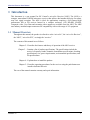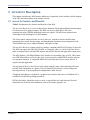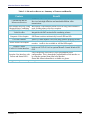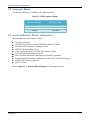
1
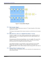
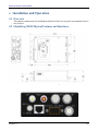
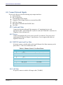
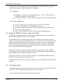
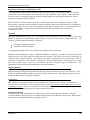
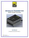
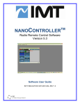
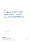
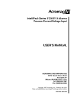
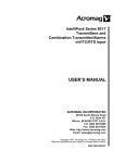
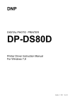
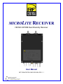
MICROLITE RECEIVER
HD/SD COFDM Dual Diversity Receiver
User Manual
IMT PUBLICATION: M23-0005-00A, REV 1.1
MicroLite Receiver User Manual
Revision History
Date
May 16, 2011June 13, 2011
August 8th. 2011
October 12, 2011
11/05/2011
Revision
0.1D
0.2D (BETA)
.3D
Modified by
Dave Anderson
(Mike Hardy)
Mike Hardy
Mike Hardy
Sean Van
11/27/2011
.4D
Sean Van
01/05/2011
.5D
Sean Van
01/23/2011 –
02/06/12
.6D
Sean Van
02/07/2012
1.0
Sean Van
02/14/2012
1.1
Sean Van
0.0D
Description
Initial Writing
Ongoing updates and clarifications
Clarified future dual-band option
Added Theory of Operation and Description
Added Formats, formatting, and
Specifications
Updated FCC and CE
Updated, added up to date drawings,
updated specifications and formatting.
Updated operational data.
Review and Initial Release
Changed Chapter 4 to Installation and
Operation. Added Figure 4.1
MicroLite Receiver
User Manual
Publication: M23-0005-00A
IMT, LLC.
200 International Drive
Mt. Olive, NJ, 07828, USA.
T +1 908 852 3700 F +1 908 813 0399
www.imt-solutions.com
Revision 1.1
2
MicroLite Receiver User Manual
We make every effort to ensure our documentation is as accurate and as complete as possible. In the event that you find any errors or
omissions, please contact Customer Tech Support at (908) 852-3700, or via email at [email protected].
© Copyrighted 2012 - IMT, LLC - Mount Olive, New Jersey 07828
NOTICE
This device complies with part 15 of the FCC Rules. Operation is subject to the following two conditions: (1) This
device may not cause harmful interference, and (2) this device must accept any interference received, including
interference that may cause undesired operation.”
Revision 1.1
3
MicroLite Receiver User Manual
microLite Receiver
User Manual
Contents
1
Introduction ___________________________________________________________________ 7
1.1
2
Manual Overview _________________________________________________________________ 7
MICROLITE Description ____________________________________________________________ 9
2.1
microLite Features and Benefits _____________________________________________________ 9
2.2
Frequency Bands ________________________________________________________________ 11
2.3
microLite Receiver Theory of Operation ______________________________________________ 11
2.3.1
2.3.2
2.3.3
2.3.4
2.3.5
2.3.6
2.3.7
2.3.8
2.3.9
2.4
Dual Antenna Inputs _____________________________________________________________________ 12
Dual Microwave Receiver COFDM Demodulator Circuits ________________________________________ 12
Maximal-Ratio Combining Circuit __________________________________________________________ 12
MPEG4 Decoder ________________________________________________________________________ 13
Video Outputs __________________________________________________________________________ 13
Audio Outputs __________________________________________________________________________ 13
User Data Output _______________________________________________________________________ 13
Video over IP Encapsulation for Streaming Video ______________________________________________ 13
Faceplate Status Display and Preset User Interface ____________________________________________ 13
Remote Control and Firmware _____________________________________________________ 13
2.4.1
2.4.2
2.4.3
3
Remote Control via Ethernet ______________________________________________________________ 13
Remote Control via RS-232 _______________________________________________________________ 14
Firmware updates _______________________________________________________________________ 14
Specifications_________________________________________________________________ 16
3.1
Frequency Bands and RF Performance _______________________________________________ 16
3.2
Modulation Modes_______________________________________________________________ 16
3.3
Diversity _______________________________________________________________________ 16
3.4
MPEG 4 Decoder ________________________________________________________________ 16
3.4.1
3.4.2
Video _________________________________________________________________________________ 16
Audio _________________________________________________________________________________ 16
3.5
System ________________________________________________________________________ 17
3.6
Power Requirements _____________________________________________________________ 17
3.7
Environmental __________________________________________________________________ 17
3.7.1
3.7.2
3.7.3
3.8
4
Temperature Range _____________________________________________________________________ 17
Altitude _______________________________________________________________________________ 17
Physical Characteristics __________________________________________________________________ 17
User Interface and Remote Control__________________________________________________ 17
Installation __________________________________________________________________ 19
Revision 1.1
4
MicroLite Receiver User Manual
4.1
Overview ______________________________________________________________________ 19
4.2
Identifying MLR Physical Features and Interfaces ______________________________________ 19
4.3
Physical Installation ______________________________________________________________ 21
4.4
Connect External Signals __________________________________________________________ 22
4.4.1
4.4.2
4.4.3
4.4.4
4.5
5
Audio and Video ________________________________________________________________________ 22
Power ________________________________________________________________________________ 22
RS232 Control and User Data ______________________________________________________________ 22
ASI Out _______________________________________________________________________________ 22
Connect Antennas _______________________________________________________________ 23
Operation ___________________________________________________________________ 25
5.1
Power up the MicroLite Receiver ___________________________________________________ 25
5.2
Pre-Configure the MLR user options _________________________________________________ 25
5.3
Control and LED Interface _________________________________________________________ 25
5.3.1
5.3.2
Buttons: _______________________________________________________________________________ 26
Status Indicators: _______________________________________________________________________ 26
5.4
Using the MLR to Receive Audio and Video ___________________________________________ 26
5.5
Verify Operation_________________________________________________________________ 26
5.6
Streaming Video over IP/Ethernet __________________________________________________ 27
5.7
Using the MLR to Receive User Data _________________________________________________ 27
5.8
Maintenance Information _________________________________________________________ 27
Figures
Figure 2-1: Internal Block Diagram __________________________________________________________________ 12
Figure 4-1: Output Connectors ______________________________________________________________________ 20
Figure 4-3: MLR Antenna Connectors _________________________________________________________________ 23
Figure 5-1: Front Panel Controls and Indicators ________________________________________________________ 25
Tables
Table 2-1: MICROLITE RECEIVER - Summary of Features and Benefits ________________________________________ 10
Table 2-2: MLR Frequency Bands ____________________________________________________________________ 11
Table 4-1: Output Connectors _______________________________________________________________________ 20
Table 4-2: Remote Control / User Data Pinout __________________________________________________________ 22
Revision 1.1
5
MicroLite Receiver User Manual
Chapter One
1
Introduction
Revision 1.1
6
MicroLite Receiver User Manual
1 Introduction
This document is a user manual for RF Central’s microLite Receiver [MLR]. The MLR is a
compact, narrowband COFDM microware receiver that utilizes dual antenna diversity for robust,
error free signal reception. The MLR is ideal for applications requiring a full featured high
performance HD or SD receiver housed in a compact enclosure. ASI, HD-SDI, SD-SDI,
Composite video, User Data and streaming video outputs are available from the MLR. The MLR
uses industry standard output connectors for compatibility with a wide range of AV equipment.
1.1 Manual Overview
Throughout this manual, the product is referred to as the “microLite”, the “microLite Receiver”,
the “MLR”, “microLite RX”, or simply the “receiver.”
The contents of this manual are as follows:
Chapter 2 – Describes the features and theory of operation of the MLR receiver.
Chapter 3 – Contains a list of product specifications. The specifications include the
receiver’s frequency bands, channels, demodulator specifications, decoding
specifications, size, power requirements, environmental specifications, and
I/O specifications.
Chapter 4 – Explains how to install the product.
Chapter 5 – Describes operating procedures for the receiver using the push button user
interface built into the unit.
The rear of the manual contains warranty and repair information.
Revision 1.1
7
MicroLite Receiver User Manual
Chapter Two
2
Description
Revision 1.1
8
MicroLite Receiver User Manual
2
MICROLITE
Description
This chapter describes the MLR features and theory of operation. It also includes a block diagram
of the MLR and a description of the internal circuits.
2.1 microLite Features and Benefits
Table 2-1 summarizes key features and benefits of the MLR.
The microLite Receiver is a receiver that utilizes advanced silicon tuners and dual antenna inputs
for robust, error free signal reception. The MLR can receive either HD or SD video
transmissions using COFDM modulated microwave signals. The MLR uses maximal-ratio
combining to take advantage of its dual antennas.
The silicon tuners employed in the microLite Receiver includes low noise amplification,
automated gain control, mixing, tuning, and demodulation functions on one integrated circuit.
This facilitates low power, high performance, and space savings.
The microLite Receiver contains a built-in, industry compliant, MPEG4 (H.264 part 10) decoder.
The MLR can output ASI, HD-SDI, SD-SDI, or Composite video, as well as User Data. Stereo
audio is included on the ASI and SDI outputs, and the MLR has left and right audio output jacks.
The MLR features a 100 Mbps Ethernet LAN interface for streaming video over IP. This feature
uses UDP/IP and allows received video to be viewed remotely using MPEG4 decoder software
on a personal computer. A compatible MPEG4 decoder that runs on your remote host PC is
required for this application.
The top panel of the microLite Receiver has signal strength, status, and monitoring LEDs that
provide useful information at a glance. The user interface also features a selector button for
choosing between 16 pre-programmed configurations called “Presets”.
Though the unit ships pre-configured, a graphical user interface that runs on a Windows PC is
available to modify the operating parameters.
IMT has the ability, should the need ever arise, to provide the user with firmware files and
instructions for local firmware installation, such as for feature upgrades, etc.
Revision 1.1
9
MicroLite Receiver User Manual
Table 2-1: MICROLITE RECEIVER - Summary of Features and Benefits
Feature
Benefit
COFDM facilitates high data rates and robust signal reception.
Receives both high definition and standard definition video
transmissions.
Dual Antenna Diversity Using Best aspects of the transport stream received using either antenna is
Maximal-Ratio Combining
used, yielding robust, error free reception.
MPEG4 (H.264 part 10)
Industry standard video decoding.
Video Decoder
Integrated with IMT maximal-ratio combining scheme.
ASI, HD-SDI or SD-SDI, and Compatible with industry standard A/V equipment.
Composite Video Outputs
SDI format switches automatically between HD and SD.
An RS-232 data channel is received along with the program streams.
User Data Channel
Line audio outputs for connection to headphones, an amplifier, or
Stereo Audio Line Outputs
recorder. Audio is also available in ASI and SDI outputs.
The MLR is pre-programmed for its operating environment using a
Remote Control
built-in web GUI via LAN or optional Remote Control Windows PC
Via RS-232 Serial Interface
GUI.
Users can quickly select one of 16 pre-programmed preset
Faceplate User Interface with configurations. This is through the programmable serial interface or
Presets and Status LED’s
by using the optional front panel user interface.
Status and Alarm information is available at a glance.
Integrated in small form factor.
Rugged, Compact Housing
COFDM HD and SD
Microwave Receiver
Revision 1.1
10
MicroLite Receiver User Manual
2.2 Frequency Bands
The microLite Receiver is available in the following bands:
Table 2-2: MLR Frequency Bands
Base Part Number
Frequency (GHz)
21MLR
23MLR
58MLR
2.025-2110
2.200-2.400
5700-6000
2.3 microLite Receiver Theory of Operation
Major blocks in the MLR diagram include:
Dual Antenna Inputs
Dual Microwave Receiver and COFDM Demodulator Circuits
Dual Input Maximal Ratio Combining Circuit
MPEG4 Video Decoding Circuit
Video Output Interfaces: ASI, SDI, and Composite Video
Left and Right Audio Output Interfaces
Preset Selection and Status Monitoring User Interface (Optional)
Programmable Serial Interface and Internal Control CPU With Flash Memory
Interface For Firmware Upgrades
Power Circuitry
Refer to Figure 2-1: Internal Block Diagram for following discussion.
Revision 1.1
11
MicroLite Receiver User Manual
Figure 2-1: Internal Block Diagram
2.3.1 Dual Antenna Inputs
The MLR has two SMA antenna input connectors. The input impedance of the antenna
connectors are 50 ohms.
The frequency band supported by the antenna connectors are labeled next to the antenna
inputs.
2.3.2 Dual Microwave Receiver COFDM Demodulator Circuits
The MLR is capable of receiving COFDM transmissions from compatible products in
multiple bands. The receiver standards supported by the MLR support high data rates
with low error rates.
Each antenna input is filtered and amplified by a low noise amplifier. The output of the
amplifier is filtered again at the input of the RF receiver circuit. The receiver mixer
down converts the received signals to the internal IF frequency.
The COFDM demodulator is programmable to support transmission modes offering
different data rates (Refer to Chapter 5 for more information). The output of the
COFDM demodulator circuits contains transport streams carrying audio, video, and user
data.
2.3.3 Maximal-Ratio Combining Circuit
This feature enhances the robustness of the receiver when line of site obstructions occur
in the transmission path.
Revision 1.1
12
MicroLite Receiver User Manual
2.3.4 MPEG4 Decoder
The MLR contains a built-in MPEG4 (H.264 part 10) compliant decoder. The decoder
audio and video output is available on the SDI output jack. Both HD-SDI and SD-SDI
are output on the SDI jack.
2.3.5 Video Outputs
Video output jacks include:
ASI – MPEG4 encoded transport stream
SDI – HD-SDI and SD-SDI audio and video
Composite Video – The MLR composite video output circuit automatically
outputs either NTSC or PAL, per the user specified settings.
2.3.6 Audio Outputs
The MLR has left and right audio line output jacks. Stereo audio is also part of the ASI
and SDI video outputs. The Audio output jacks are 75 Ohm RCA connectors.
2.3.7 User Data Output
A data channel is transmitted with the audio and video information. Access of the data
channel is through the RS-232 serial interface output connector. The baud rate and other
RS-232 parameters are programmable.
2.3.8 Video over IP Encapsulation for Streaming Video
The MLR features a 100 Mbps Ethernet LAN interface for streaming video over IP.
This feature allows received video to be viewed remotely using MPEG4 decoder
software on a personal computer.
2.3.9 Faceplate Status Display and Preset User Interface
If you commonly use several configurations in the field, the faceplate LED preset
settings and “Set” selector button provide a quick way to change pre-programmed
configurations. Status information is also presented by LED’s. Refer to Chapter 5 for
more information.
The Preset configurations are pre-programmed using the Remote Control Windows PC
GUI or Web GUI interface. To program a preset, adjust any of the settings within the
MLR, and then save the current group of settings by assigning a Preset number. The
Presets are recalled by using either the faceplate user interface or the Remote Control
PC GUI or the Web GUI interfaces.
2.4 Remote Control and Firmware
2.4.1 Remote Control via Ethernet
An Ethernet port allows remote control of all configuration options, as well as
monitoring of internal status and settings.
The IMT NanoController GUI is available for controlling the unit via the Ethernet port.
Any Windows compatible computer running Windows XP/Vista/7 with 500 MB of
memory and 1 GHz Pentium or above can be used. Refer to Chapter 5, “Operation” for
more information.
Revision 1.1
13
MicroLite Receiver User Manual
2.4.2 Remote Control via RS-232
An RS-232 command set is implemented to allow remote control of all configuration
options, as well as monitoring of internal status and settings. Commands and responses
are sent via the RS-232 serial interface on the 9-pin connector.
The IMT NanoController GUI is available for controlling the unit via the RS-232 serial
interface. Any Windows compatible computer running Windows XP/Vista/7 with 500
MB of memory and 1 GHz Pentium or above can be used. Refer to Chapter 5,
“Operation” for more information.
2.4.3 Firmware updates
Update unit firmware via the Ethernet interface. Contact IMT Tech Support for
additional details.
Revision 1.1
14
MicroLite Receiver User Manual
Chapter Three
3
Specifications
Revision 1.1
15
MicroLite Receiver User Manual
3 Specifications
3.1 Frequency Bands and RF Performance
Base Part Number
Frequency (GHz)
23MLR
2.025-2.500
58MLR
5.725-5.850
Tuning step size: 250 KHz
Frequency stability: ± 10ppm
3.2 Modulation Modes
Modes are auto detected within modulation format
Modulation Formats:
COFDM (DVB-T)
Carriers:
2K
Constellation:
QPSK, 16QAM, 64 QAM
Code Rate:
1/2, 2/3, 3/4, 5/6, 7/8
Guard Interval:
1/32, 1/16, 1/8, 1/4
Bandwidth:
6 MHz, and 8 MHz
3.3 Diversity
Dual Receivers
Channels: 2 input Maximum Ratio Combining
3.4 MPEG 4 Decoder
3.4.1 Video
Method:
Video Coding;
Video Output;
SD-SDI output:
HD-SDI output:
MPEG-4 Part 10/H.264
AVC
Composite and SDI
ANSI/SMPTE 259M
ANSI/SMPTE 292M
3.4.2 Audio
Audio Channels:
Audio Coding:
Audio Sample Rate:
Audio Output Levels:
Embedded Audio:
Revision 1.1
1 Stereo, 2 Mono
ISO/IEC 11172-3(Layer I/II)
48Khz
Direct line output or adjustable gain output.
Available in SDI as embedded audio
16
MicroLite Receiver User Manual
3.5 System
ASI Output:
User Data:
Latency
Ethernet:
Streaming Video:
Remote Control:
Auto output rate follows modulation
or fixed output user selectable
(PCR Retime stamp)
RS232 Side channel; 300-115K Baud
(*using MicroLite Transmitter):
o 4 frames in Low Latency Mode for all
formats except PSF
o 5 frame in Low Latency Mode for PSF
formats
100 Mbps Ethernet interface.
Streaming MPEG-TS over UDP/RTSP
Via LAN and/or PC GUI
3.6 Power Requirements
Input range:
Power consumption:
DC: +9 to +32
9W Typical
3.7 Environmental
3.7.1 Temperature Range
Full specification:
Storage:
Humidity:
-10° to 50°C Ambient
-40° to 80°C
0 to 95% non-condensing
3.7.2 Altitude
Operating:
Storage:
20,000ft (6,000 m)
50,000ft (15,000 m)
3.7.3 Physical Characteristics
Size:
Weight:
3.7" x 5" x 1.5"
620g/1.4lbs
3.8 User Interface and Remote Control
One button control (16 user defined presets)
Remote RS232
WEB GUI
Revision 1.1
17
MicroLite Receiver User Manual
Chapter Four
4
Installation and Operation
Revision 1.1
18
MicroLite Receiver User Manual
4
Installation and Operation
4.1 Overview
This chapter contains steps for installing the MicroLite Receiver in typical environments where it
may be used.
4.2 Identifying MLR Physical Features and Interfaces
4-1: microLite Outline Drawing
Revision 1.1
19
MicroLite Receiver User Manual
Figure 4-2: Output Connectors
Item
Left, Right
SDI
Video
ASI
DC In
Ethernet Port
Remote / User Data
Revision 1.1
Table 4-1: Output Connectors
Description
Audio Line Outputs
HD-SDI or SD-SDI Output
Composite Video (PAL or NTSC)
Encoded Video Output
Power Supply Input
100mbps LAN Interface
RS-232 Connector
Connectors
75 Ohm RCA
BNC
BNC
BNC
2.5mm jack
RJ45
DB-9
20
MicroLite Receiver User Manual
______________________________________________________________
! WARNING – DO NOT OPEN THE MICROLITE!
The MicroLite contains no user serviceable parts. Do not open the
MicroLite housing. Failure to comply will result in voiding of the
warranty.
______________________________________________________________
4.3 Physical Installation
Remove microLite Receiver (MLR) from the case. The mounting bracket with MLR is
preassembled.
Attach MLR to the Magic Arm using tripod mount bracket.
Connect Video output as needed (BNC connector).
Connect audio output as needed (RCA jacks).
Connect RX antennas (larger sector directional) to the RF Inputs (N-Type).
Aim directional sector antennas in the general area of MLT operation.
Connect power source to the MLR using the power cable supplied.
Select MLR preset using the set button.
Revision 1.1
21
MicroLite Receiver User Manual
4.4 Connect External Signals
The microLite Receiver has the following major output interfaces:
Power Interface
RS-232 Serial Port
Left and Right Audio Outputs
Composite Video Output (not down converted from HD)
ASI Video Output
SDI Output for HD-SDI and SD-SDI Video
User Data
4.4.1 Audio and Video
Connect the desired Audio and Video outputs to A/V monitoring devices with
appropriate cables. The MLR has RCA jacks for audio and 75ohm BNC connectors for
Composite Video, SDI and ASI.
4.4.2 Power
Connect an appropriate DC power source to the DC in connector. The power source
requirements are listed in Chapter 3, Specifications. Power supplies and cables are
supplied with the unit.
4.4.3 RS232 Control and User Data
If desired, connect a suitable cable to the 9 pin D Remote/User Data connector per the
pinout below. Cables are available from IMT.
Pin
1
2
3
4
5
6
7
8
9
Table 4-2: Remote Control / User Data Pinout
Function
Notes
N/C
RX / IN A
Remote Control
TX / OUT A
Remote Control
N/C
Ground
Ground
TX / OUT B
User Data
RX / IN B
User Data
N/C
N/C
4.4.4 ASI Out
If required, connect a suitable ASI output cable (75Ω BNC).
Revision 1.1
22
MicroLite Receiver User Manual
4.5 Connect Antennas
Connect antennas directly to the N RF input connectors, or via 50-Ohm cables.
WARNING
If cabling the MLR directly to a transmitter (e.g. for testing) you must use
in-line RF attenuators. 50dB minimum recommended.
Figure 4-3: MLR Antenna Connectors
Revision 1.1
23
MicroLite Receiver User Manual
Chapter Five
5
Operation
Revision 1.1
24
MicroLite Receiver User Manual
5 Operation
While this chapter contains basic information about the operation of the microLite Receiver, the
programming of the unit (including preset configuration) via the NanoController GUI is not
covered. Please refer to the NanoController manual (IMT Publication: M27-0001-00A) for
detailed information on how to program and configure the unit.
In this section, you will find information on how to use the MLR to receive video, audio, and user
data, and how to stream video to a PC or network.
5.1 Power up the MicroLite Receiver
Turn on the power to the overall system.
The MLR requires up to 20 seconds to complete the power up sequence. Supply current will
jump up in steps as internal circuits are powered. The final DC supply current will settle after 20
seconds.
The MLR contains flash memory, which retains all stored preset configuration settings when the
unit is not powered.
5.2 Pre-Configure the MLR user options
The MLR has a wide range of programmable settings. Before using the MLR in your application,
you should pre-configure it to for the settings you want to use in your application. Settings are
selected and configured using the NanoController software, or a third party alternative. Please
refer to the NanoController documentation for details, or contact IMT Technical Support.
5.3 Control and LED Interface
Figure 5-1: Front Panel Controls and Indicators
The MLR has several Buttons and LED’s on the front panel, to perform basic operation and
view unit status. Any changes made via a remote control interface will be reflected by the front
panel LED’s.
Revision 1.1
25
MicroLite Receiver User Manual
The MLR can be pre-configured using the programmable serial interface and then quickly
changed between preset modes using the “Set” pushbutton.
5.3.1 Buttons:
Set Button - Advances the unit through the presets. The 1-12 LED’s indicate in
GREEN, which preset is currently active.
SCAN(future Feature) - Scan available presets until it locks on an incoming signal.
5.3.2 Status Indicators:
Alarm - Normally OFF. If an Alarm is present, the LED will be RED.
Rx Lock - When YELLOW, the demodulator is locked.
Streaming - Indicates that the unit is streaming video through the Ethernet port.
Decoder – Decoder Operating
RSSI - LED’s will light to provide a Received Signal Strength Indicator.
5.4 Using the MLR to Receive Audio and Video
The MLR receives and demodulates COFDM radio signals from the microLite Transmitter. It
then decodes the MPEG4 transport stream for output.
The dual antenna diversity feature of the MLR is used to maximize the robustness of video
reception. The primary goal of dual antenna diversity is to enable the user to prevent line of site
obstruction on the transmission path from causing receiver errors to occur. By separating the
antennas, the user has two chances to receive the signal properly, regardless of obstructions
between the transmitter and MLR antennas. Properly directing your antenna to the transmit
source is key obtaining the best range possible.
Video may be viewed on a monitor, which accepts SD Composite video, or SDI. MPEG4
encoded video is also included in the transport stream on the ASI output, and must be decoded
using an MPEG4 decoder prior to viewing on a monitor.
Audio can be output to a recorder or amplifier. Audio is also embedded in SDI outputs, and
included in the transport stream on the ASI output.
Streaming video and audio can be output via a laptop or PC with a compatible MPEG4 decoder
program.
5.5 Verify Operation
After installing the MLR, turn on the power to the receiver and your overall system. The LED’s
on presets 1-4 will sequentially illuminate until boot up is complete.
Verify operation of the MLR by using the following methods:
Revision 1.1
26
MicroLite Receiver User Manual
Use the Remote Control Interface and/or the Web GUI interface to verify the status of
the MLR.
Use a video monitor to view SD Composite video (NTSC or PAL, as appropriate).
Display video on equipment with ASI or SDI input connectors. This may include video
analysis equipment or PC’s with ASI or SDI input cards used for video storage and
editing.
To stream video over IP use the Ethernet connection to a PC or laptop running a
compatible MPEG4 audio and video decoder program.
Note: When operating in low latency, external MPEG4 software/hardware decoders
may not work.
5.6 Streaming Video over IP/Ethernet
The MLR is pre-configured to stream video over IP on its Ethernet port. To stream video over
IP use the Ethernet connection to a PC or laptop running a compatible MPEG4 audio and video
decoder program.
.
5.7 Using the MLR to Receive User Data
View User Data by using a laptop PC with a Terminal program. The User Data is through the
RS-232 (DB-9) connector. Refer to Table 2-1 for pin-out. Contact IMT for details.
5.8 Maintenance Information
Follow these procedures when maintaining the device:
Dry the device immediately if it comes into contact with water or other liquids. Warranty
does not cover liquid damage.
Do not submerge the device or use it directly in rain.
Do not open the device. This voids the warranty.
Keep the device clean by wiping with a soft, dry cloth. If necessary, dampen only using a
solution suitable for cleaning electronic devices. Warranty does not cover cleaning
damage.
Revision 1.1
27
MicroLite Receiver User Manual
Proprietary Information and Disclaimer Notice
All information and graphic images contained within this manual are the sole property of IMT, LLC, and are
issued in the strictest of confidence. This material may not be reproduced, stored, copied, or converted in any
form, nor shall it be disclosed to others or used for manufacturing or any other purpose without the written
permission of authorized IMT personnel.
IMT has made every effort to ensure the accuracy of this material at the time of printing. However, as the
specifications, equipment, and this manual are subject to change without notice, IMT assumes no responsibility
or liability whatsoever for any errors or inaccuracies that may appear in this manual, or for any decisions based
on its use. This manual is supplied for informational purposes only and should not be construed as a
commitment by IMT.
Warranty
Equipment manufactured by IMT, LLC is warranted to meet all published specifications and to be free from
defects in material and workmanship within a period of two years from date of original shipment. The
company’s liability under this warranty is limited to:
Servicing or adjusting equipment.
Replacement of defective parts.
Any equipment returned to the factory shall have the freight paid for by the buyer.
Equipment showing damage by misuse, abnormal conditions of operation, or attempts to repair by other than
authorized service personnel shall be excluded from this warranty. IMT shall in no event be responsible for
incidental injury or property damage. Since IMT has no control over conditions of use, no warranty is made or
implied as to suitability for the customer’s intended use, beyond such performance specifications as are made
part of the purchase order. There are no warranties expressed or implied, except as stated herein. This
limitation on warranties shall not be modified by verbal representations.
Shipping Damage
Equipment shipped FOB IMT shall become the property of buyer upon delivery and receipt from carrier. Any
damage in shipment should be handled by the buyer directly with the carrier. Immediately request the carrier’s
inspection upon evidence of damage in shipment.
Field Service
IMT products are designed with easy access to components to facilitate service. However, some modules
cannot be service in the field. To prevent voiding of the warranty, please contact Tech Support before servicing
or making any repairs. The user is cautioned to read all module descriptions in this manual. Warnings are
included in the circuit descriptions and on certain modules themselves.
Replacement Modules
Troubleshooting to the component level is often not cost-effective and frequently impossible. Often the
practical method of effecting repairs is to substitute known good spare modules for suspect units. Replacement
modules for our standard product line are usually available.
Revision 1.1
28
MicroLite Receiver User Manual
Technical Support Information
Technical Support personnel are available to extend technical assistance to customers while installing,
operating, or troubleshooting IMT equipment. Please have your model number and serial number available.
Telephone
During IMT business hours, 8:30am - 5:30pm EST (-5 Hours, GMT), call:
US ........................................................... 908-852-3700
International ............................................ 001-1-908-852-3700
After hours, call:
US or International .................................. 888-531-3892
Email
Email address ....................................................... [email protected]
Internet
Web address ......................................................... www.imt-solutions.com
Equipment Returns
If equipment cannot be successfully restored through telephone consultation, return to the factory may be
required. Loaner items may be available until the repaired items are returned.
For out-of-warranty equipment only: We evaluate all returned units, and then confers with the client on
corrective action. If no fault is found, or no corrective action is authorized, a diagnostic fee may be charged.
Prior to returning products to the factory, please obtain a return material authorization (RMA) number and
shipping instructions from Tech Support.
When returning equipment, it is very helpful to enclose a note containing the following:
RMA number.
Serial number.
A detailed description of the problem.
Name of an engineer or technician we may contact regarding problems encountered.
A “ship to” and “bill to” address.
Ship all returns to:
IMT, LLC
Attn: RMA# (your RMA number)
200 International Drive
Mt. Olive, NJ, 07828, USA
(908) 852-3700
For International returns:
In addition to the instructions above, when shipping internationally we recommend the use of a courier such as
Federal Express, UPS, etc, and that the goods be shipped DOOR-TO-DOOR PRE-PAID. This will reduce
Customs costs, handling charges and delays. Enclose all the information above, plus a statement that the
equipment was manufactured in the United States (the latter is needed to expedite customs processing).
Revision 1.1
29
MicroLite Receiver User Manual
IMT, LLC.
200 International Drive
Mt. Olive, NJ, 07828, USA.
T +1 908 852 3700 F +1 908 813 0399
www.imt-solutions.com
Revision 1.1
30