1
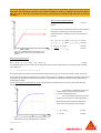
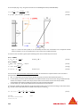
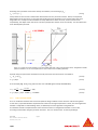
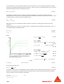
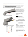
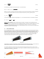
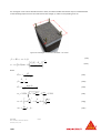
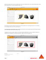
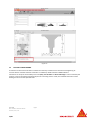
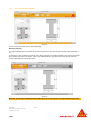
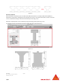
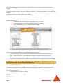
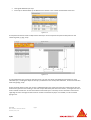
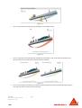
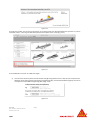
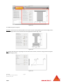
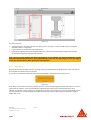
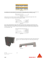
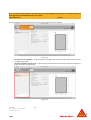
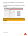
USER GUIDE Sika® Carbodur® calculation software DECEMBER, 2013 / 1.0.0 / SIKA SERVICES AG / TABLE OF CONTENTS 1 2 2.1 Theoretical Background Flexural Strengthening 2.1.1 Initial Situation 3 3 4 2.1.2 Ultimate Limit State (ULS) 6 2.1.3 Serviceability Limit State (SLS) 8 2.1.4 Fire situation check 10 2.1.5 Bond check 12 2.2 2.3 3 3.1 3.2 3.3 3.4 3.5 3 Introduction 16 18 Shear Strengthening Column confinement Use of Sika® Carbodur® software Installation and activation Introduction Flexural strengthening. 3.3.1 Cross section and concrete 20 20 20 23 24 3.3.2 Steel reinforcement 26 3.3.3 Loading 28 3.3.4 CFRP strengthening 33 3.3.5 Bond check 37 3.3.6 Printout 39 Shear reinforcement. 3.4.1 Cross section and concrete 39 39 3.4.2 Loading 40 1.1.1 Laminates 41 3.4.3 Printout 43 Column reinforcement 3.5.1 Cross section and concrete 43 43 1.1.2 Laminates 43 3.5.2 Printout 45 46 Legal note User Guide English Sika® Carbodur® calculation software December, 2013, 1.0.0. 2/47 1 INTRODUCTION The aim of this software is to assist the user in calculating the CFRP dimensions required to provide (a) flexural strengthening, (b) shear strengthening and (c) column confinement. These three topics are dealt with in the next sections, which present the theoretical basis of the calculations. The calculation procedures employed in this program are based on the fib Bulletin No. 14: "Design and use of Externally Bonded FRP Reinforcement for RC Structures". Additional and auxiliary calculation methods are taken from “Eurocode 2: Design of concrete structures”, as well as ”Eurocode: ‐ Basis of structural design”. 2 THEORETICAL BACKGROUND 2.1 FLEXURAL STRENGTHENING Figure 2-1: parabola-rectangle stress block for concrete under compression (left) and sample in a beam under flexure (right) Reinforced concrete elements, such as beams, slabs and columns, may be strengthened in flexure through the use of FRP composites epoxy‐bonded to their tension zones, with the direction of fibres parallel to that of high tensile stresses (member axis). The calculations described below address both the Ultimate Limit State (ULS) and the Serviceability Limit State (SLS). For the design, the parabola‐rectangular method is used by the software to determine the compressive strain and stress ratio of the concrete across the section´s height (Fig. 2‐1). The design values for the reinforcing steel are derived from the characteristic values, fyk. In the case of ULS verifications, the software uses a simplified bilinear diagram, with a horizontal branch extending from the point where fyd is achieved (Fig. 2‐2). Figure 2-2: simplified design stress-strain diagram for reinforcing steel (tension and compression) User Guide English Sika® Carbodur® calculation software December, 2013, 1.0.0. 3/47 (2.1a) For the design the value of the modulus of elasticity, Es ,is assumed to be 200 GPa. The design values for the Sika® Carbodur® laminates are obtained assuming a linear stress‐strain diagram (Fig. 2‐3): (2.1b) Figure 2-3: simplified design stress-strain diagram for CFRP composite (blue) compared to steel. 2.1.1 INITIAL SITUATION The first step in the calculations is to find the initial strain, Ɛo, that is present in the extreme fibre of the cross section when the strengthening operations take place. This strain is the result of a moment Mo (service moment, no load safety factors are applied) acting at the critical cross section during strengthening (e.g. due to the self‐ weight of the structure and any additional load acting at the time of the strengthening), and may be calculated based on equilibrium of internal forces and moments (Fig. 2‐4). Figure 2-4: determination of the initial strain at the extreme fibre (left), and its influence on the loaded, strengthened member (right) The calculation to determine the initial strain at the extreme fibre is based on cracked section properties. A parabolic‐rectangular concrete stress block is used (Fig. 2‐5). The concrete safety factor γc and long‐term effects coefficient for concrete αcc are disabled to evaluate the strain distribution. Concrete stress is determined according to the following equations: for fck < 50MPa: 1 1 , for 0 ≤ Ɛc ≤ 2‰ User Guide English Sika® Carbodur® calculation software December, 2013, 1.0.0. 4/47 (2.1.1a) for 2‰ ≤ Ɛc ≤ 3,5‰ (2.1.1b) (2.1.1c) (2.1.1d) (2.1.1e) for 0 ≤ Ɛc ≤ Ɛc2 (2.1.1f) for Ɛc2 ≤ Ɛc ≤ Ɛcu2 (2.1.1g) for fck ≥ 50MPa: ‰ 2,0 0.085 ‰ 2,6 1.4 23.4 1 50 35 1 , The initial Ɛo strain influence on the ULS calculation is usually limited. However, its influence on the Serviceability Limit State may cause great differences in the necessary quantity of FRP. Hence, the user should input a realistic Mo value for the expected moment during the CFRP installation. Subsequently: Internal force equilibrium (initial situation): Figure 2-5: Parabola-rectangle scheme (blue) used for the determination of the concrete deformation at initial state (2.1.1h) ∙ ∙ (2.1.1i) ∙ ∙ (2.1.1j) Compressive depth, δ and Fc values are exactly determined by the software in an iterative process. Assuming that Ɛco < 2‰, the compressive force developed by the parabola stress block can be estimated by the equation: ∙ ∙ 6 ∙ 1000 ∙ 1000 ∙ (2.1.1k) (2.1.1l) (2.1.1m) And δ depth can be estimated by: ∙ ∙ 2 ∙ ∙ ∙ ∙ Moment equilibrium (initial situation): where xo is the depth of neutral axis from the extreme compressive fibre and Fs1, Fs2 are the forces developed by the bottom and top steel reinforcement, respectively. fck is the characteristic (cylinder) strength of concrete. From the numerical solution of these equations, the maximum compressive concrete strain, Ɛco, and the neutral axis depth, xo, can be calculated. Finally, the initial strain Ɛo is given as: User Guide English Sika® Carbodur® calculation software December, 2013, 1.0.0. 5/47 (2.1.1n) Figure 2-6: Stress and strain profiles under the acting moment during the strengthening process, 2.1.2 ULTIMATE LIMIT STATE (ULS) The ultimate limit states are associated, among others, with the failure of a structural member and they generally concern safety of people. For the verification of the ultimate limit state, design actions will not exceed the design resistance of the structure. Once Ɛo is calculated, the analysis of the critical cross section for the ULS (Ultimate Limit State) is performed on the basis of Fig. 2‐7,which shows the strain profile and internal forces at the Ultimate Limit State. Forces equilibrium is carried out by using a parabola‐rectangular stress block, as provided by Eurocode 2 (Fig. 2‐8). Concrete stress is determined according to the following equations: for fck < 50MPa: 1 1 , for 0 ≤ Ɛc ≤ 2‰ (2.1.2a) for 2‰ ≤ Ɛc ≤ 3,5‰ (2.1.2b) (2.1.2c) for fck ≥ 50MPa: ‰ 2,0 ‰ 2,6 1.4 23.4 1 0.085 50 , 35 (2.1.2d) (2.1.2e) for 0 ≤ Ɛc ≤ Ɛc2 (2.1.2f) for Ɛc2 ≤ Ɛc ≤ Ɛcu2 (2.1.2g) (2.1.2h) 1 and : User Guide English Sika® Carbodur® calculation software December, 2013, 1.0.0. 6/47 where γc is the partial factor for the concrete, and αcc is the coefficient taking account of long term effects on the compressive strength. Figure 2-7: Stress and strain profiles for the ultimate limit state, strengthened member. Note that strains are limited (in red) by the maximum compressive strain of the concrete (3,5‰ in case of concrete class ≤50MPa), and the limiting strain of the CFRP, Ɛf,lim. Maximum Ɛc is limited to Ɛcu2 (3,5‰ for fck ≤ 50MPa). In the same way, CFRP strain, Ɛf, is limited to a limiting strain, Ɛf,lim, to treat debonding (Fig. 2‐7). Both values should be selected according to the Eurocode2 parameters and the respective National Annexes. Steel stress is determined by the equation: (2.1.2i) (2.1.2j) where and γs is the partial factor for the steel. For CFRP‐reinforced structures, the calculations are based on the assumption that one of the following two desirable failure modes govern the behaviour: Following yielding of the internal tension steel reinforcement the concrete crushes in the compression zone, as the strain in the top fibre exceeds Ɛcu2 (3,5‰ for fck ≤ 50MPa). Following yielding of the internal tension steel reinforcement the FRP reaches a limiting strain, Ɛf,lim (this is a simplified way to prevent debonding of the FRP in areas where flexure dominates the response, e.g. mid‐span of simply supported beams. Figure 2-8: Parabola-rectangle scheme (red) used for the determination of the concrete deformation at ultimate. User Guide English Sika® Carbodur® calculation software December, 2013, 1.0.0. 7/47 Some local regulations may also limit the maximum yielding strain of the internal reinforcement at the ultimate limit state. The information provided by the software includes the necessary graphical and numerical data to allow the user to check this requirement if necessary, and modify the quantity of CFRP laminates to meet this condition. Internal force equilibrium (ULS): where: , (2.1.2k) is the concrete compressive force from the parabolic‐ rectangular stress block, and is automatically determined by the software by means of an iterative process. ∙ ∙ , where ∙ (2.1.2l) ∙ ∙ , where ∙ (2.1.2m) ∙ ∙ , where (2.1.2n) (2.1.2o) , Figure 2-9: Simplified bilinear scheme (red) for the reinforcing steel, used for the ULS analysis of the member. Moment equilibrium (ULS): , (2.1.2p) The solutions of eqs. 2.1.2k and 2.1.2p are performed numerically through iterations, yielding the required FRP cross section Af. 2.1.3 SERVICEABILITY LIMIT STATE (SLS) The Serviceability Limit State concerns the functioning of the structure or structural members under normal use. For the SLS (Serviceability Limit State), the analysis of the critical cross section is performed, according to Eurocode parameters, for the two possible load combinations: Characteristic combination of loads and Quasi‐permanent combination of loads. For the Characteristic combination of loads, the calculations are performed as in the case of the ULS, with the following modifications: The parabolic‐rectangular stress block is determined by using the characteristic concrete strength (Fig. 2‐10). Ms,d is replaced by the acting moment (under the characteristic combination) Mser,ck; Under the characteristic load combination, steel and concrete stresses are limited to: ∙ 0,6 Figure 2-10: Parabola-rectangle scheme (blue) used for the determination of the concrete deformation at ultimate. User Guide English Sika® Carbodur® calculation software December, 2013, 1.0.0. 8/47 0,8 (2.1.3a) (2.1.3b) As an example (Fig. 2‐11), using C25 concrete class and B500 grade steel (E=200.000 MPa): 0,8 0,8 0,6 . 2‰ (2.1.3c) 15MPa (2.1.3d) 0,6 ∙ 25MPa Figure 2-11: Stress and strain profiles for the serviceability limit state under characteristic loads, strengthened member. (Limits are marked in red, for an example based on C25 concrete class and B500 grade steel) The stress in the concrete is given by the following stress‐strain relationship of concrete: for fck < 50MPa: 1 1 , for 0 ≤ Ɛc ≤ 2‰ (2.1.3e) (2.1.3f) (2.1.3g) (2.1.3h) for fck ≥ 50MPa: ‰ 2,0 1.4 23.4 1 0.085 1 50 , for 0 ≤ Ɛc ≤ Ɛc2 For the case of quasi‐permanent combination of loads, the calculations are performed as in the case of the characteristic load, with the following modifications: a. b. Mser,ck is replaced by the acting moment (under the quasi‐permanent load combination) Mser,qp; For the Quasi‐permanent load combination, the software takes creep into account using a simplified creep model. The analysis is made in one step (creep is taken into account from the initial load, without intermediate load stages) considering the quasi‐permanent load combination. A creep factor (φ = 2) is used to determine the compressive concrete strains. c. The previous models consider both the compressive deformation of the concrete according to the instant loads (Ɛc), as well as the creep deformation related to the long‐term loads (Ɛcc). , φ φ , User Guide English Sika® Carbodur® calculation software December, 2013, 1.0.0. 9/47 (2.1.3i) According to the parabolic stress block used by the software, and assuming Ec≈Ecm: , ~ 1 φ ∙ (2.1.3j) Creep relates to the increase in deformation with time due to the permanent actions. Hence, the expected deformation of the concrete is (1+ φ) times that resulting from the application of an instant load of the same magnitude. As a consequence of the additional creep deformation of the concrete, and to maintain strain compatibility, the depth of the neutral axis increases (compared to that for short term loads). This also affects the strain developed by the steel. Figure 2-12: Stress and strain profiles for the serviceability limit state under quasi-permanent loads, strengthened member. (Limits are marked in red for an example based on C25 concrete class and B500 grade steel). d) Under the quasi‐permanent combination of loads, steel and concrete stresses are limited to: ∙ 0,45 0,8 (2.1.3k) (2.1.3l) As an example (Fig. 2-12), using C25 concrete class and B500 grade steel (E=200.000 MPa): 0,8 0,8 0,45 0,45 ∙ 25MPa . 2‰ 11.25MPa (2.1.3m) (2.1.3n) 2.1.4 FIRE SITUATION CHECK Fire is an accidental situation that involves exceptional design conditions of the structure and the acting loads. In case of fire, unprotected CFRP is expected to be lost due to the high temperatures. Hence, the unstrengthened member is subjected to reduced design loads, as defined by the local regulations and guidelines. The software includes a simplified check of the resistance of the un‐strengthened member in case of fire, according to Eurocode 2: Design of concrete structures ‐ Part 1‐2: General rules ‐ Structural fire design. User Guide English Sika® Carbodur® calculation software December, 2013, 1.0.0. 10/47 The combination of actions used by the software for the verification of an un‐strengthened member strength is based on the simplified method indicated in Eurocode 2: ‐ Part 1‐2, 2.4.2 using a reduction factor (ηfi = 0.7) that is applied to the design moment at ultimate limit state. , ∙ , (2.1.4a) If SLS designs have been input, the software includes the possibility of using the quasi‐permanent load combination for the fire situation, according to the recommendations in Eurocode 1: Actions on structures ‐ Part 1‐ 2: General actions ‐ Actions on structures exposed to fire. , , , (2.1.4b) Alternatively, users can also define the design moment in case of fire, according to their needs or the local regulations. Partial safety factors for materials are taken equal to 1, following the recommendation of Eurocode 2: ‐ Part 1‐2, 2.3: Design values for material properties. , , 1 (2.1.4c) 1 (2.1.4d) Hence: , , (2.1.4e) for fck < 50MPa: 1 , , 1 , for 0 ≤ Ɛc ≤ 2‰ (2.1.4f) for 2‰ ≤ Ɛc ≤ 3,5‰ (2.1.4g) for fck ≥ 50MPa: ‰ Figure 2-13: Parabola-rectangle scheme (green) used for the determination of the concrete deformation in case of fire under flexural loads. 2,0 ‰ 2,6 1.4 23.4 , 50 , 35 (2.1.4i) (2.1.4j) (2.1.4h) , 0.085 1 1 for 0 ≤ Ɛc ≤ Ɛc2 (2.1.4k) for Ɛc2 ≤ Ɛc ≤ Ɛcu2 (2.1.4l) (2.1.4m) And for the reinforcing steel: , , The software checks if the un‐strengthened member strength is able to support the expected loads in case of fire, without the contribution of the CFRP. Otherwise, Sikacrete® 213F or other alternative fire protection methods must be used to ensure the protection of the CFRP. User Guide English Sika® Carbodur® calculation software December, 2013, 1.0.0. 11/47 The software does not analyze the structural behavior of the reinforced concrete member over time, for the fire load case. 2.1.5 BOND CHECK In elements with sufficient internal or external shear reinforcement, peeling‐off of the CFRP reinforcement is usually related to the opening of flexural cracks that propagate horizontally along the beam or slab, in the direction of decreasing moment. As these cracks open they induce high interfacial shear stress that may cause CFRP debonding. Due to this, it is necessary to ensure a proper anchorage of the CFRP on un‐cracked concrete beyond the outermost flexural crack position in ultimate limit state. The force developed by the CFRP in the section corresponding to the outermost crack (Nf,d) needs to be anchored to the available un‐ cracked concrete length (lb) (Fig. 2‐15). The software includes 2 different possibilities for the end anchorage verification: Figure 2-14: flexural cracks distribution at ultimate, strengthened member Option a): Approximate calculation for simply supported elements with homogeneous distribution of loads. This calculation comprises all the intermediate steps, including: The determination of the cracking moment magnitude of the beam/slab, considering the real distribution of the steel reinforcement in the area adjacent to the support. The expected position of the outermost crack at ultimate limit state. The calculations of the force developed by the CFRP strengthening in that section. The calculation of the maximum anchorable force, according to the concrete class, concrete surface compaction, uncracked concrete length and the geometry of the element and the CFRP reinforcement. Figure 2-15: End anchorage in an un-cracked concrete zone. The software determines the bending moment (Mcr) at which the tension in the lowest fibre equals the mean flexural tensile strength of the selected concrete (fctm,fl), as follows: Figure 2-16: strain and stress profile corresponding to crack User Guide initiation English Sika® Carbodur® calculation software December, 2013, 1.0.0. 12/47 max , 1,6 ∙ ; (2.1.5a) where: h is the total member depth in mm fctm is the mean axial tensile strength of the concrete: 0,30 ∙ 2,12 ∙ ln 1 for concrete class ≤C50/60 (2.1.5b) for concrete class >C50/60 (2.1.5c) The CFRP contribution for this calculation is dismissed as being negligible. Once the Mcr value is obtained, the expected position of the outermost flexural crack is determined by assuming: Simply supported member. Homogeneous load distribution. CFRP contribution as negligible. The estimation of this position (Fig. 2‐17), can be accomplished by determining the point at which the moment envelope at ULS equals the value corresponding to Mcr, previously calculated. The software considers the “shift rule” as indicated in Eurocode 2. It involves a horizontal displacement (al) of the bending moment envelope, to take into account the tensions generated in the area as a secondary consequence of the shear forces in the beam/slab. In accordance with this, the initially available length for the anchorage (x) is reduced. The horizontal displacement is estimated in a simplified way by the software, according to the static depth (d) and following the criteria: Figure 2-17 0.45 ∙ for beams, assuming the existence of internal shear reinforcement, a 0.9 ∙ (2.1.5d) (2.1.5e) for slabs, assuming a reduced or inexistent quantity of internal shear reinforcement. Finally, the available bond length (lb) is defined by subtracting the non‐accessible length located within the support (ai). In the case of continuous beams/slabs, the approximate determination of the available anchorage length is not included in the software. The anchorage is achieved by extending the CFRP to the compression zone hence it is necessary to have detailed information of the load distribution in order to estimate the neutral point of the bending moment envelope. The estimation of the anchorage length in the case of continuous beams and positive bending moments can be done using the following process (Fig. 2‐18): The position where the envelope of the bending moment equals zero (x) at ultimate, must be determined. After this, a horizontal displacement of the diagram (al) is taken into account, according to the “shift rule” indicated in Eurocode 2. User Guide English Sika® Carbodur® calculation software December, 2013, 1.0.0. 13/47 From this defined section, the designer must provide the maximum anchorage length, lb,max, as follows: , ∙ ∙ (2.1.5f) Similary, in the case of negative bending moments, the CFRP is anchored to the compression zone. In the same way, the shift rule is applied to take into account the shear forces (Fig. 2‐19). As the position corresponding to the zero moment varies significantly according to the different load combinations, some guidelines recommend to use: , ∙ ∙ 1 (2.1.5g) for the anchorage of CFRP used to increase negative moment capacity. At this stage, the software determines the initial strain expected at the bottom fibre of the section as a consequence of the existing load at the time of strengthening. As a simplification, the initial moment expected (Mo,cr) in the determined Figure 2-18 outermost cracked section at ultimate is obtained as result of the ratio between the ultimate moment (Msd) of the strengthened member at mid‐span, and the initial moment at mid‐span (Mo). According to this, the software determines the initial strain at the extreme tension fibre of the section (un‐cracked section) corresponding to the expected initial moment (Mo,cr). The calculation is based on strain compatibility, taking into account the contribution of the concrete (compressed and tensioned) as well as the existing steel in the area adjacent to the support (Fig. 2‐20). After this, a new calculation is carried out based on the reinforced cracked section to evaluate the strain (Ɛf,cr) developed by the CFRP in ULS (Fig. 2‐21). Figure 2-19 User Guide English Sika® Carbodur® calculation software December, 2013, 1.0.0. 14/47 Figure 2-20 Figure 2-21 As consequence of this expected strain, the CFRP force can be determined: , A ∙ , (2.1.5h) where Af is the cross section of the CFRP reinforcement. Once the force to be developed by the CFRP (Nf,d) at the outermost flexural crack is known, it is necessary to check if it can be anchored; according to the available anchorage length (lb) obtained previously. For the situations where lb ≥ lb,max, assuming: User Guide English Sika® Carbodur® calculation software December, 2013, 1.0.0. 15/47 ∙ , ∙ (2.1.5i) (2.1.5j) The maximum force which can be anchored, Nfa,max can be determined: , 0,64 ∙ k ∙ k ∙ b ∙ ∙ ∙ Where kc is a factor accounting for the state of compaction of concrete (can be generally assumed to be equal to 1.0, but kc=0.67 for CFRP bonded to concrete faces with low compaction), and kb is a geometry factor: 1,06 ∙ 1 (2.1.5k) In the cases where the available anchorage length lb < lb,max, the maximum bond force is calculated according to: , ∙ , ∙ 2 , (2.1.5l) Option b): Exact calculation, valid for any kind of beam or support. In this option, the user defines the value corresponding to the cracking moment for the strengthened member, as well as the available length of un‐cracked concrete. The software determines the force to be developed by the CFRP in that section, according to the characteristics of the beam/slab, and verifies if the awaited CFRP force (Nf,d) can be anchored to the length of the available un‐cracked concrete surface (lb). 2.2 SHEAR STRENGTHENING Shear strengthening of RC members using FRP may be provided by bonding the external reinforcement with the principal fibre direction as parallel as practically possible to that of maximum principal tensile stresses, so that the effectiveness of the FRP is maximized. For the most common case of structural members subjected to lateral loads, the maximum principal stress trajectories in the shear‐critical zones form an angle with the member axis that may be taken roughly equal to 45o. However, it is normally more practical to attach the external CFRP reinforcement with the principal fibre direction perpendicular to the member axis (Fig. 2‐22). Figure 2-22 Closed jackets or properly anchored strips are always preferable compared with open jackets, as in the latter case CFRP premature debonding is usually expected, hence the effectiveness of the CFRP is reduced. For members subjected to predominantly uniformly distributed loading the design shear force need not to be checked at a distance less than d from the face of the support (in addition it should be verified that the shear at the support does not exceed VRd,max) (Fig. 2‐23). User Guide English Sika® Carbodur® calculation software December, 2013, 1.0.0. 16/47 Figure 2-23 The external FRP reinforcement may be treated in analogy to the internal steel (accepting that the CFRP carries only normal stresses in the principal CFRP material direction), assuming that at the ultimate limit state in shear (concrete diagonal tension) the CFRP develops an effective strain in the principal material direction, Ɛf,e which is in general, less than the tensile failure strain, Ɛfu. The effective strain depends on the degree of CFRP debonding when the shear capacity of the RC is reached; that is, on the type of anchorage (properly anchored CFRP, e.g. closed jackets, versus poorly anchored FRP, i.e. open jackets). Hence, the shear capacity of a strengthened element may be calculated as follows (e.g. in Eurocode 2 format): Vrd = min (VRd,s+Vfd,VRd,max) (2.2a) where Vfd, the contribution of FRP to the member’s shear capacity (Fig. 2‐24), is given by the following expression. V fd 0.9 fd ,e E f f bw d 1 cot a sin a (2.2b) Figure 2-24 In the above equation Ef is the elastic modulus of CFRP composite, according to the characteristics of the SikaWrap® and the Sikadur® resin used, bw is the width of the cross section, d is the static (or effective) depth, α is the angle between the principal FRP fibre orientation and the longitudinal axis of the member (90º for vertical CFRP schemes in beams), Ɛfd,e is the design value of the effective FRP strain and ρf is the FRP composite volumetric ratio, equal to (2tf/bw)sinα for continuously bonded CFRP of thickness tf, or (2tf/bw)(bf/sf) for CFRP reinforcement in the form of strips or sheets of width bf (perpendicular to the fibre orientation) at a spacing sf (axis to axis of strips along the member axis). Equation 2.2b may be solved for the thickness of CFRP required to provide a shear resistance equal to Vfd. The design value of the effective CFRP strain may be estimated as follows: Fully wrapped or properly anchored CFRP: User Guide English Sika® Carbodur® calculation software December, 2013, 1.0.0. 17/47 fd , e 0.3 2/3 0.8 0.17 fu f cm E f f 0.6% min , 1.2 1.2 (2.2c) U‐shaped CFRP jackets: fd , e 0.3 0.56 2/3 2/3 0.8 0.17 fu f cm 0.8 0.65 10 3 f cm Ef f Ef f 0.6% min , , 1.2 1.3 1.3 2 (2.2d) 2 In the above, fcm is the mean compressive strength of concrete in N/mm and Ef is taken in kN/mm . 2.3 COLUMN CONFINEMENT The main objectives of confinement are: a. b. c. to enhance concrete strength and deformation capacities, to provide lateral support to the longitudinal reinforcement and to prevent the concrete cover from spalling. In the case of circular columns, these goals can be achieved by applying external FRP jackets, either continuously over the surface, or discontinuously as strips. In the case of rectangular columns, confinement can be provided with rectangular‐shaped reinforcement, with corners rounded before application. Note that rectangular confining reinforcement, although possible, is less effective as the confinement action is mostly located at the corners and a significant jacket thickness needs to be used between corners to restrain lateral dilation and rebar buckling. The stress‐strain response of CFRP‐confined concrete is illustrated schematically in Fig. 2.25. The figure displays a nearly bilinear response with a sharp softening and a transition zone at a stress level that is near the strength of unconfined concrete, fco. After this stress the tangent stiffness changes only a little, until the concrete reaches its ultimate strength fcc when the jacket reaches tensile failure at a stress ff,e and a corresponding strain Ɛfu,e, which is, in general, less than the uniaxial tensile strength Ɛfu. This reduction in failure stress is attributed to several reasons, including: (a) the triaxial state of stress in the CFRP (due to axial loading and confining action, but also due to bending, e.g. at corners of low radius); and (b) the quality of execution (potential local ineffectiveness of some fibres due to misalignment, and overstressing of others; damaged fibres at sharp corners or local protrusions etc). Figure 2-25: Stress-strain curves for plain (unconfined) and FRP-confined concrete. User Guide English Sika® Carbodur® calculation software December, 2013, 1.0.0. 18/47 For rectangular cross sections with dimensions b and h, the effect of CFRP confinement may be calculated based on the following expressions for the confined concrete strength fcc and the corresponding strain Ɛcu: Figure 2-26: Rectangular cross section with radius “r” at corners. f cc Esec,u cu f co E E Esec,u cu co 1 51 2 1 cc c Esec,u Ec Ecc E 1 cc Eco (2.3a) (2.3b) where Ec 1 2 fu , e Esec,u Ecc 1 2.254 1 7.94 h 2 h 2 1 0.6 1.4 0.8 1,b b f co b 1,b Ec 1 f co co (2.3c) (2.3d) (2.3e) (2.3f) (2.3g) (2.3h) 1 2 f co co 1 51 2 1 2t f h 1,b f co k e f f ,e 2 User Guide English Sika® Carbodur® calculation software December, 2013, 1.0.0. 19/47 1,b 1.254 f co ke 2 2 b 2 R h 2 R 1 3 Ag (Confinement effectiveness coefficient) (2.3i) And: 3 Ec = initial tangent modulus of concrete. Ɛco = 0.002 (strain corresponding to fco). Ag = gross sectional area of concrete. USE OF SIKA® CARBODUR® SOFTWARE 3.1 INSTALLATION AND ACTIVATION Once installed, the software needs to be activated in order to ensure its operation indefinitely. Otherwise, the user can use it only for a limited period of time. In order to request the activation code, the user must input the information requested in the activation form (Fig. 3‐1). During a limited period of time, the software can be launched by selecting the “Compatibility mode“ option without any previous activation. Figure 3-1 An automatic e‐mail will be generated and delivered to Sika. The activation code will be received by the user within the next days, who must enter activation code in the corresponding field, and press the “Activate software“ button. In case of new versions or additional modifications, the software is automatically updated if connected to the Internet. The update procedure can be forced manually or adjusted by clicking the first tab on the upper‐left corner (Sika logo), and selecting “Sika Carbodur Update“ option. 3.2 INTRODUCTION The software package Sika® Carbodur® is a user friendly, simple and reliable design tool for the selection of required CFRP dimensions to provide flexural strengthening, shear strengthening or confinement in reinforced concrete sections. User Guide English Sika® Carbodur® calculation software December, 2013, 1.0.0. 20/47 When the program starts, the user is asked to select one of the following three cases: flexural reinforcement, shear force reinforcement, or column reinforcement (Fig. 3‐2). Figure 3-1 The selection can be done either by selecting one of the schematic icons in the upper left corner, or one of the main drawings shown in the main screen (Fig. 3‐3). The area located on the left of the screen contains the information concerning the project, which will be included in the subsequent printout documents (Fig. 3‐4). Language and country selection appears on the upper band. By selecting the country, the software database is adapted to the available Sika® strengthening product range for that territory (Fig. 3‐5). Figure 3-2 User Guide English Sika® Carbodur® calculation software December, 2013, 1.0.0. 21/47 Figure 3-3 Regardless of the type of strengthening selected, the calculation process is organized into successive stages, which are shown in the tabs situated in the top of the screen. The type and quantity of stages vary as a function of the selected strengthening method and the data introduced by the user (Fig. 3‐6). If inadmissible or incoherent values are entered during the process, a hint will be presented in the lower left area of the screen. The user can directly move to the corresponding screen by double‐clicking on the hint text (Fig. 3‐7). Figure 3-4 User Guide English Sika® Carbodur® calculation software December, 2013, 1.0.0. 22/47 Figure 3-5 Figure 3-6 3.3 FLEXURAL STRENGTHENING. The flexural reinforcement calculation includes the necessary calculations for the flexural strengthening of concrete beams and slabs with Sika® Carbodur® or SikaWrap® CFRP laminates in ULS conditions. Calculations to verify the serviceability limit state (SLS), fire situation and bond anchorage are also covered by the program, and can be enabled or disabled by the user according to their needs, the available information of the existing structure and the expected loads. User Guide English Sika® Carbodur® calculation software December, 2013, 1.0.0. 23/47 3.3.1 CROSS SECTION AND CONCRETE Figure 3-7 The user needs to provide input as described below: Geometry selection The upper left area shows the profiles of the most characteristic concrete elements working under flexure(Fig. 3‐ 9). A slab option is also available by selecting “slab”. When selected, the software modifies some internal parameters with respect to the beam calculation. Such as the CFRP distribution, geometry limits of the profile and some aspects regarding bond anchorage checks. Figure 3-8 Note that, by selecting a suitable geometry profile, the user can recreate part of complex elements (Fig. 3‐10). User Guide English Sika® Carbodur® calculation software December, 2013, 1.0.0. 24/47 Figure 3-9 Geometry definition Once the profile is selected, the user can define the different dimensions. A sample model with the different dimensions nomenclature is displayed on the left side of the screen. A real draft of the profile, shown on the main screen, is updated according to the values introduced by the user (Fig. 3‐11). Note that complex profiles can be achieved by using the existing profile options (Fig. 3‐12). The software applies some geometrical limits to reduce the risk of user typing errors. Figure 3-10 Figure 3-11 User Guide English Sika® Carbodur® calculation software December, 2013, 1.0.0. 25/47 Concrete definition Concrete is defined by the user, either by selecting the concrete class or by entering the mean compressive strength. Note that the concrete class is defined according to Eurocode 2. It consists of the respective characteristic (5%) compressive cylinder strength fck, and cube compressive strength fck,cube, determined at 28 days, in accordance with EN 206‐1. The mean compressive strength is taken as fcm=fck+8 MPa. As an example: C25/30 concrete class: Characteristic (5%) concrete cylinder compressive stress: fck=25 MPa. Characteristic (5%) concrete cube compressive stress: fck,cube=30 MPa. Mean compressive strength: fcm=25 MPa + 8 MPa = 33 MPa. Figure 3-12 The user must also define additional concrete parameters (Fig. 3‐13), such as: γc, partial safety factor for concrete. This factor reduces the compressive concrete strength of the concrete for the ULS calculation. The αcc coefficient takes into account the long term effects on compressive strength and any un‐ favourable effects resulting from the way the load is applied. It reduces the value of the compressive stress block for the ULS calculation and the flexural resistance of the existing member in the fire situation. A creep factor (ϕ = 2) for the concrete is automatically used to determine the compressive concrete strains for long‐term load cases (SLS, quasi‐permanent load combination). 3.3.2 STEEL REINFORCEMENT The existing steel reinforcement is input by the user in the next stage of the program. It comprises a versatile interface that allows the introduction of complex steel distributions (Fig. 3‐14). It comprises some aspects, as: Entering of several steel layers (max. 10). User Guide English Sika® Carbodur® calculation software December, 2013, 1.0.0. 26/47 Steel grade definition per layer. Each layer is defined either by its effective cross section or the number and diameter of the bars. Figure 3-13 The top band contains the tool to add/remove steel layers. It also comprises the partial safety factor for the reinforcing steel (γs) (Fig. 3‐15). Figure 3-14 The steel definition tool is shown on the left column. The user can select and modify the parameters for each individual layer, including the depth of the layer, the effective cross section/rebar definition, and the characteristic steel strength (Fig. 3‐16). Finally, the draft shown on the main screen is updated based on the reinforcing steel input. Note that the bars are shown evenly spaced in the drawing. In the case of layers defined by the steel cross‐section, a homogeneous line is shown instead of steel bars. At least one bottom tensile steel layer is necessary for the calculations. Some limits regarding concrete coverage and the maximum number of steel bars by layer are included, in order to reduce typing errors. User Guide English Sika® Carbodur® calculation software December, 2013, 1.0.0. 27/47 Figure 3-15 3.3.3 LOADING Once the geometries and materials of the existing member are defined, the user must input the information related to the existing loads on the member at the time the CFRP is installed, as well as and design moments after the CFRP reinforcement is installed. Figure 3-16 The main screen shows additional information (Fig. 3‐17) in a graphical way, including: The acting moment during strengthening: User Guide English Sika® Carbodur® calculation software December, 2013, 1.0.0. 28/47 Figure 3-17 The current (bottom) and required (top) strengths of the member in ULS: Figure 3-18 The current (bottom) and required (top) strengths of the member in SLS, under both characteristic and quasi‐permanent load combination (if the SLS check is enabled): Figure 3-19 The current strength of the existing, unreinforced element (bottom) and the estimated acting load (top) in case of fire (if the fire situation check is enabled): User Guide English Sika® Carbodur® calculation software December, 2013, 1.0.0. 29/47 Figure 3-20 The left area includes the numerical input boxes. The limiting values are displayed beside the input box. In case of unsuitable values, a warning text will be displayed at the bottom of the screen (Fig. 3‐22). Figure 3-21 The load definition consists of 3 different stages: a) The minimum necessary loads to evaluate the strengthening performance in ULS; this part comprises the definition of the acting moment during the strengthening (Mo), and the demanded strength by the user as consequence of the CFRP strengthening (Ms,d) (Fig. 3‐23). Figure 3-22 User Guide English Sika® Carbodur® calculation software December, 2013, 1.0.0. 30/47 As explained in 2.1.1, it is important to note that the existing moment during the strengthening (Mo) generates an imposed deformation of the tensile steel that cannot be restored unless prestessing the CFRP. This moment can have a significant influence on the necessary CFRP quantity in the SLS in case of a substantial initial moment. Therefore, the user must input a realistic value for the acting moment (Mo) expected during the strengthening process. This should not include load factors and will be essentially composed of the existing dead loads and the reduced combination of the expected live loads during the installation. Due to safety reasons, this value cannot exceed: The strength of the unstrengthened member under the Serviceability Limit State (characteristic load), if SLS verification is enabled. 80% of the strength of the unstrengthened member under the Serviceability Limit State (characteristic load), if SLS verification is disabled. The limiting values are shown beside the input box. After this, the user must input the necessary strength of the element after the strengthening, i.e. the expected moment corresponding to the factored loads at ultimate (Ms,d). Due to safety reasons, the maximum strength of the member after the CFRP reinforcement is limited to the following values: 3x the original strength at ultimate of the unstrengthened member, if the serviceability limit state (SLS) check is activated. 1,6x the original strength at ultimate of the unstrengthened member if user doesn´t proceed with the SLS check. For obvious reasons, the user cannot request a strength lower than the existing capacity before the strengthening. b) Serviceability limit state (SLS) check (Fig. 3‐24): Figure 3-23 By enabling this option, the software verifies the performance of the reinforced concrete member under quasi‐ permanent and characteristic combination of loads: Those service loads correspond to the un‐factored combination of loads, as indicated in Eurocode, Eurocode 2 and the respective National Annexes. ‐The quasi‐permanent combination of loads corresponds to the sum of the permanent load plus a limited percentage of variable actions. This value is determined so that the total period of time for which it will be exceeded represents a large fraction of the reference period. ‐The characteristic combination of loads corresponds to the sum of the permanent load plus a significant percentage of variable actions. This magnitude is chosen so as to correspond to a prescribed probability of not being exceeded on the unfavorable side during a reference period, taking into account the design working life of the structure and the duration of the design situation. As shown in 2.1.3, the strains and stresses developed by the compressed concrete and tensile steel must be limited under certain values, to avoid excessive creep and/or cracking. The user must input the expected SLS design moments for the strengthened member: User Guide English Sika® Carbodur® calculation software December, 2013, 1.0.0. 31/47 The characteristic load combination value must equal or exceed the expected quasi‐permanent load combination value, but cannot exceed the value requested for ULS. c) Fire situation check: When the user enables this option (Fig. 3‐24), the software analyses the performance of the existing (un‐ strengthened) member in case of fire, by using the strength of concrete and steel without safety factors, as determined by Eurocode 2. The user is requested to establish the design load. In case of fire there are 3 options displayed: Figure 3-24 If SLS loads have been defined, the software takes the quasi‐permanent load (Mser,qp,d, Eq. 2.1.4b) as default value. If not, the default value is adjusted to 70% of the design load at ultimate (0.7xMs,d, Eq 2.1.4a). The user can directly input the value by using the third option, which allows entry of a specific value based on an exact calculation of the fire load combination, according to the local regulations. After this, the information is shown in the graphical area, together with a message that indicates if the CFRP strengthening needs protection in case of fire, according to the expected load and the strength of the un‐ strengthened member (Fig. 3‐26 and 3‐27). Figure 3-25 User Guide English Sika® Carbodur® calculation software December, 2013, 1.0.0. 32/47 Figure 3-26 The software evaluates the initial strength of the un‐strengthened member and the expected loads in case of fire, according to that indicated in fib Bulletin 14, parts 3.1.2.5 and 3.2.2. Any additional protection for the reinforced concrete member as resulting of the strengths development throughout a fire situation (concrete and/or steel reinforcement) must be determined independently. 3.3.4 CFRP STRENGTHENING After the introduction of the suitable initial and design loads, the hints area at the bottom of the screen will disappear, and new tabs (“laminates” and “user‐defined setting”) will be displayed at the top of the screen. Both tabs allow the user to introduce the necessary Sika® Carbodur® or SikaWrap® CFRP laminates; The first option (laminates) gives the user automatically those calculated combinations based on the correct number of each size/type of CFRP laminates to meet the ULS and SLS requirements (if enabled), according to the available width of the soffit. The second option (user‐defined setting) allows the user to meet more flexibility, by allowing the combination of any type and quantity of CFRP layers. Both options can be used interchangeably. Laminates When selected, the software automatically establishes the necessary quantity of CFRP to meet the requested ULS (and SLS if enabled), corresponding to the effective CFRP strain Ɛf,eff, input at the top (8‰ as default). According to this initial estimation, the user can access all the information related to the different load stages, by clicking on the icons located in the top of the screen; the main screen, which displays the numerical and graphical data, will change depending on the selection (Fig. 3‐28). User Guide English Sika® Carbodur® calculation software December, 2013, 1.0.0. 33/47 Figure 3-27 The different options comprise: Overview: summarizes the necessary CFRP cross‐section and the resisting bending moments throughout the different stages, both for the unreinforced and strengthened member (Fig. 3‐29). Figure 3-28 Mo: displays the information regarding the initial state of the member, under the acting moment during the strengthening (Fig. 3‐30). Figure 3-29 User Guide English Sika® Carbodur® calculation software December, 2013, 1.0.0. 34/47 Ms: displays the strains and stress distribution of the strengthened member at ultimate, as well as the ductility check, as indicated in fib Bulletin 14, section 3.3 (Fig. 3‐31). Figure 3-30 Mser,ck: exposes the information related to the state of the strengthened member under SLS, characteristic load (Fig. 3‐32). Figure 3-31 Mser,qp: finally, this stage presents the stress and strains profiles of the strengthened section under the quasi‐ permanent load combination, considering the effect of creep (Fig. 3‐33). Figure 3-32 User Guide English Sika® Carbodur® calculation software December, 2013, 1.0.0. 35/47 The user must select the suitable CFRP laminate combination. After selecting the type of CFRP (top), the software automatically shows the appropriate number and sections required to achieve the necessary cross‐section (Fig. 3‐ 34). Figure 3-33 Based on the geometry of the concrete section, the software automatically disables (grey) those combinations that cannot be placed due to the available space. Note that the maximum number of Sika® Carbodur® layers that can be displayed is 3, and the minimum distance to the edge of the beam should equal the concrete cover of the internal steel reinforcement (fib Bulletin 14, sections 7.2.1.1 and 7.2.1.2). The maximum number of SikaWrap® layers that can be displayed is 5. Important note: in case of using SikaWrap® fabrics, the software calculation is based on the real performance of the CFRP composite obtained as a result of using the chosen SikaWrap® and the appropriate Sikadur® resin, as indicated in the corresponding Product Data Sheet, and according to the EN 2561 test method. Hence, the displayed result cannot be extended to any composite obtained by the use of any other resin or by any other system different from that indicated in the Product Data Sheet. The selected option is finally applied by clicking the “Apply selected” icon situated in the upper left corner of the screen. Click “none” to delete the selection. Figure 3-34 After a number and type of CFRP laminate is selected, all the graphical and numerical information regarding the different load stages is automatically updated. User‐defined setting In this tab the user can freely combine the appropriate amount and type of laminates, so as to obtain or exceed the necessary CFRP cross section. The appearance is similar to that shown in the previous stage, except for the central area, which includes the tools needed to make the distribution of the different layers of reinforcement (Fig. 3‐36). User Guide English Sika® Carbodur® calculation software December, 2013, 1.0.0. 36/47 Figure 3-35 This area comprises: Add/remove icons, including the option for filling the current layer or all the available layers by using the selected lamella in a single click. Layer selection, by means of the top selection box. Information regarding the overall selected CFRP area, as well as the remaining area required to meet the necessary area required, displayed at the bottom. Once a project is saved regarding the flexural strengthening of a RC member, the selected combination of CFRP laminates is automatically stored as a “User‐defined setting“. Hence, the user must simply access to this stage to recover the chosen selection when opening that existing project. 3.3.5 BOND CHECK By entering this optional stage, the user can verify if the force developed by the CFRP section can be anchored to the available uncracked concrete at ultimate. The process is initiated by clicking the selection box positioned in the upper left corner (Fig. 3‐37). Figure 3-36 Once done, the calculation process is activated. The user must verify the longitudinal steel distribution in a section adjacent to the support, as this steel distribution influences the location of the outermost flexural crack at ultimate. In case of an “exact calculation” (see below), this check is not necessary. The user is automatically shown the steel distribution corresponding to the middle of the span (previously input in the steel definition stage) as default (Fig. 3‐37). User Guide English Sika® Carbodur® calculation software December, 2013, 1.0.0. 37/47 Figure 3-37 The software also includes the possibility of reducing the bonding capacity of the anchorage as a consequence of a low compaction concrete surface (e.g. if surface was not in contact with the formwork during casting). Figure 3-38 Finally, the user can also select a direct calculation, by introducing the available bond length and the value corresponding to the cracking moment of the strengthened member. Figure 3-39 Or, for simply supported beams or slabs, where the determination of the anchorage can be critical due to the flexural cracking at ultimate, the software includes an option which automatically determines the position of the outermost crack position at ultimate, as well as all the necessary parameters to determinate the feasibility of the end anchorage (Fig. 3‐41). Figure 3-40 Where ai corresponds to the distance from the centre of the support to the inner face, and L indicates the length of the simply supported span (Fig. 3‐ 42). Figure 3-41 User Guide English Sika® Carbodur® calculation software December, 2013, 1.0.0. 38/47 Note that this Approximate calculation is only valid for homogeneous load distributions, and beams with sufficient internal or external shear reinforcement. 3.3.6 PRINTOUT By selecting the Printout option, the software automatically generates a printable document with the information obtained throughout the calculation process. 3.4 SHEAR REINFORCEMENT. The shear reinforcement calculation is based on the contribution of the SikaWrap® to the shear capacity of the strengthened member under ULS. Hence, the user must previously determine the design value of the applied shear force (VEd). This value must be matched or exceeded by the sum of the design value of the shear force which can be sustained by the yielding shear reinforcement (VRd,s) plus the contribution of the CFRP (Vfd). For members subject to predominantly uniformly distributed loading the design shear force need not be checked at a distance less than d from the face of the support (in addition it should be verified that the shear at the support does not exceed VRd,max) (Fig. 3‐43). Figure 3-42 VRd = min (VRd,s+Vfd,VRd,max) 3.4.1 (3.3a) CROSS SECTION AND CONCRETE In a first stage, the geometry and concrete class is defined (Fig. 3‐44). The top band of the screen includes the geometry selection, as well as the definition of the characteristics of the concrete. The strength of the concrete can be either defined by using the characteristic (fck) or the mean compressive strength (fcm). In the left area, the user is requested to introduce the data related to the geometry of the section, which is displayed in the diagram located in the main screen. Note that it´s necessary to input the concrete cover, in order to determine the static depth of the element. User Guide English Sika® Carbodur® calculation software December, 2013, 1.0.0. 39/47 Figure 3-43 The option “Rectangle” or “T‐beam” is selected to determinate the wrapping scheme of the CFRP (full wrapping for the rectangular sections, and U‐shaped configuration in case of T‐beams, where full wrapping is not possible) (Fig. 3‐45). Figure 3-44 Shear strengthening of columns where all four sides are accessible is typically of the closed‐type. Moreover, shear strengthening of T‐beams with mechanical anchorage systems that ensure perfect anchorage of the FRP in the compression zone may be considered to be closed‐type too. This is the case, for instance, with the CarboShear elements, if sufficient anchorage length is available through the slab. 3.4.2 LOADING The requested CFRP (Vfd) contribution is input by the user (Fig. 3‐46). Note that the CFRP shear strengthening acts in a similar way to external stirrups. Hence, they contribute to increase the design value of the shear force which can be sustained by the yielding shear reinforcement. (VRd,s). After this, the result is displayed in the next stage. User Guide English Sika® Carbodur® calculation software December, 2013, 1.0.0. 40/47 Figure 3-45 1.1.1 LAMINATES The user has the option either to select a continuous jacket scheme or a configuration based on discrete strips, in the selection box situated in the upper left corner (Fig. 3‐47). Figure 3-46 Take into account that, if the discrete strips option is selected, it is necessary to input a value for the spacings (sf). Due to safety reasons, this value is limited to 0,8d (0,8 x static depth of the element), so that no diagonal crack may be formed without intercepting a strip. In the same way, the minimum value for the spacings equals the width of the selected SikaWrap® fabric (bf), since otherwise the CFRP scheme acts as a continuous jacket. Due to these limitations, the discrete strips configuration is not possible for those beams with a limited height and/or wide SikaWrap® fabrics. Notice that, according to the geometry of the section and the wrapping scheme, 4 different configurations are possible (Fig. 3‐ 48): The area located on the left shows the available SikaWrap® range in the indicated country. The bottom section displays the width and dry thickness of the SikaWrap®. The subsequent calculation will be done according to the selected product (Fig. 3‐ 49). Figure 3-47 User Guide English Sika® Carbodur® calculation software December, 2013, 1.0.0. 41/47 Figure 3-48 Finally, the main screen displays the graphical information regarding the SikaWrap® configuration and the contribution of the CFRP to the shear strength of the member. In the bottom, the numerical data is displayed, including the necessary number of layers of the selected SikaWrap®, as well as the real contribution to the shear strength, according to the resulting number of layers (Fig. 3‐50). Figure 3-49 Important note: the software calculation is based on the real performance of the CFRP composite obtained as a result of using the chosen SikaWrap® and the appropriate Sikadur® resin, as indicated in the corresponding Product Data Sheet, and according to the EN 2561 test method. Hence, the displayed result cannot be extended to any composite obtained by the use of any other resin or by any other system different from that indicated in the Product Data Sheet. User Guide English Sika® Carbodur® calculation software December, 2013, 1.0.0. 42/47 3.4.3 PRINTOUT By selecting the Printout option, the software automatically generates a printable document with the information obtained throughout the calculation process. 3.5 COLUMN REINFORCEMENT Confinement is usually applied to members in compression, with the function of increasing their load carrying capability under axial load. The external confinement of columns is accomplished by orienting the fibres transverse to the longitudinal axis of the member. The column reinforcement module comprises two stages, as follows: 3.5.1 CROSS SECTION AND CONCRETE The geometry and concrete class is defined by the user (Fig. 3‐51). The top band of the screen includes the geometry selection, as well as the definition of the characteristics of the concrete. The strength of the concrete can be either defined by using the characteristic (fck) or the mean compressive strength (fcm). In the left area, the user inputs the data related to the geometry of the section, which is then displayed in the diagram located in the main screen. The option “Rounded rectangle” or “Circular” can be selected to define the geometry of the column. Note that, in case of rectangular sections: It´s necessary to input the radius of the edges. A greater radius increases the effectiveness of the confinement. The minimum acceptable radius is 10mm. Rectangular columns with aspect ratios h/b exceeding 2 are not allowed, as the confining effect is negligible. Figure 3-50 1.1.2 LAMINATES This screen consists of independent areas: on the upper left corner, the effective ultimate Figure 3-51 strain of the CFRP jacket is displayed. The effective ultimate strain will be less than the CFRP´s ultimate strain due to the multiaxiality of stresses in the FRP and the quality of execution (Fig. 3‐52). User Guide English Sika® Carbodur® calculation software December, 2013, 1.0.0. 43/47 Note: The default value shown for the effective strain of the CFRP (Fig. 3‐52) is based on an efficiency factor of 0.55 suggested in ACI 440.2R‐08, section 12.1. Hence: Ɛfu,eff=0,55 x Ɛfu. (3.4.2a) By using the selection boxes at the top (Fig. 3‐53), the user has the option to request: Figure 3-52 Increase of mean strength fcc: Input the required strength of the confined concrete (the target value after strengthening), and/or Increase of ultimate axial strain Ɛcu: Input the required ultimate axial strain of the confined concrete (the target value after strengthening). Figure 3-53 User Guide English Sika® Carbodur® calculation software December, 2013, 1.0.0. 44/47 The area situated on the left shows the available SikaWrap® range in the selected country. The bottom section displays the width and dry thickness of the SikaWrap®. The subsequent calculation will be done according to the selected product (Fig. 3‐54). Finally, the main screen (Fig. 3‐55) displays the graphical information regarding the SikaWrap® configuration and the new strength of the confined concrete resulting from the confinement. On the left area, the numerical data is displayed, showing the necessary number of layers of the selected SikaWrap®, as well as the ultimate axial strain of the confined concrete. Figure 3-54 Important note: the software calculation is based on the real performance of the CFRP composite obtained as result of using the chosen SikaWrap® and the appropriate Sikadur® resin, as indicated in the corresponding Product Data Sheet, and according to the EN 2561 test method. Hence, the displayed result cannot be extended to any composite obtained by the use of any other resin or by any other system different from that indicated in the Product Data Sheet. 3.5.2 PRINTOUT By selecting the Printout option, the software automatically generates a printable document with the information obtained throughout the calculation process. User Guide English Sika® Carbodur® calculation software December, 2013, 1.0.0. 45/47 LEGAL NOTE This software application is protected by copyright laws and international copyright treaties. The software application is licensed, not sold. THIS SOFTWARE APPLICATION AND THE RESULTS DERIVED FROM ITS UTILIZATION ARE INTENDED ONLY FOR USE BY PROFESSIONAL USERS WITH EXPERT KNOWLEDGE IN THE AREA OF THE INTENDED APPLICATION. USERS MUST INDEPENDENTLY VERIFY THE RESULTS BEFORE ANY USE AND TAKE INTO ACCOUNT THE SITE AND APPLICATION CONDITIONS, PRODUCT DATA SHEET AND PRODUCT LITERATURE, TECHNICAL STATE OF THE ART AS WELL AS LOCAL APPLICABLE STANDARDS AND REGULATIONS. With respect to the software application and results derived from its use, SIKA MAKES NO WARRANTIES OF ACCURACY, RELIABILITY, COMPLETENESS, MERCHANTABILITY OR FITNESS FOR ANY PURPOSE. THE SOFTWARE APPLICATION IS PROVIDED ON AN “AS‐IS” BASIS AND SIKA EXPRESSLY DISCLAIMS ANY WARRANTIES WITH RESPECT TO THE SOFTWARE APPLICATION AND RESULTS DERIVED FROM ITS USE. Sika shall not be liable for any consequential, punitive, incidental, exemplary, or special damages (including but not limited to loss of business opportunity or loss of profit) arising out of the evaluation or use of the software application and results derived from its use. The information, and, in particular, the recommendations relating to the application and end‐use of Sika products, are given in good faith based on Sika's current knowledge and experience of the products when properly stored, handled and applied under normal conditions in accordance with Sika’s recommendations. In practice, the differences in materials, substrates and actual site conditions are such that no warranty in respect of merchantability or of fitness for a particular purpose, nor any liability arising out of any legal relationship whatsoever, can be inferred either from this information, or from any written recommendations, or from any other advice offered. The user of the product must test the product’s suitability for the intended application and purpose. Sika reserves the right to change the properties of its products. The proprietary rights of third parties must be observed. All orders are accepted subject to our current terms of sale and delivery. Users must always refer to the most recent issue of the local Product Data Sheet for the product concerned, copies of which will be supplied on request. This License shall be governed by and construed and enforced in accordance with the material laws of Switzerland. The non‐mandatory conflict of laws provisions shall be excluded. Exclusive forum shall be the courts of Zürich, Switzerland. Sika®, SikaDur®, CarboDur® and SikaWrap® are registered trademarks of Sika AG. All other products and brand names may be trademarks or registered trademarks of their respective owners. Copyright Sika Services AG 2013 User Guide English Sika® Carbodur® calculation software December, 2013, 1.0.0. 46/47 Sika Services AG TM Refurbishment Version given by Vázquez David Phone: Fax: Mail: User Guide English Sika® Carbodur® calculation software December, 2013, 1.0.0. 47/47 © 2013 Sika Services AG / Nr 870 41 06