1
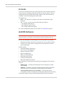
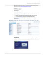
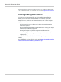
AirLink GX Series
User Guide
4114008
Rev 1
Preface
Important
Notice
Due to the nature of wireless communications, transmission and reception of data
can never be guaranteed. Data may be delayed, corrupted (i.e., have errors) or be
totally lost. Although significant delays or losses of data are rare when wireless
devices such as the Sierra Wireless AirLink GX Series device are used in a
normal manner with a well-constructed network, the Sierra Wireless GX Series
device should not be used in situations where failure to transmit or receive data
could result in damage of any kind to the user or any other party, including but not
limited to personal injury, death, or loss of property. Sierra Wireless accepts no
responsibility for damages of any kind resulting from delays or errors in data
transmitted or received using the Sierra Wireless AirLink GX Series device, or for
failure of the Sierra Wireless AirLink GX Series device to transmit or receive such
data.
Safety and
Hazards
Do not operate the Sierra Wireless AirLink GX Series device in areas where
blasting is in progress, where explosive atmospheres may be present, near
medical equipment, near life support equipment, or any equipment which may be
susceptible to any form of radio interference. In such areas, the Sierra Wireless
GX Series device MUST BE POWERED OFF. The Sierra Wireless AirLink GX
Series device can transmit signals that could interfere with this equipment.
The driver or operator of any vehicle should not operate the Sierra Wireless
AirLink GX Series device while in control of a vehicle. Doing so will detract from
the driver or operator's control and operation of that vehicle. In some states and
provinces, operating such communications devices while in control of a vehicle is
an offence.
In accordance with ANSI/ISA 12.12.1-2012, Section 16 and CSA C22.2 No 213,
Section 5.5, the following instructions and warnings apply:
This apparatus is suitable for use in Class I, Division 2, Groups A, B, C and D.
Warning: EXPLOSION HAZARD – SUBSTITUTION OF COMPONENTS MAY IMPAIR
SUITABILITY FOR CLASS I, DIVISION 2.
Avertissement : RISQUE D'EXPLOSION – LA SUBSTITUTION DE COMPOSANTS
PEUT RENDRE CE MATERIEL INACCEPTABLE POUR LES EMPLACEMENTS DE
CLASSE I, DIVSION 2.
Warning: EXPLOSION HAZARD – DO NOT DISCONNECT WHILE CIRCUIT IS LIVE
UNLESS THE AREA IS KNOWN TO BE NON-HAZARDOUS.
Avertissement : RISQUE D'EXPLOSION – NE PAS DEBRANCHER TANT QUE LE
CIRCUIT EST SOUS TENSION, A MOINES QU’IL NE S’AGISSE D’UN EMPLACEMENT
NON DANGEREUX.
Warning: DO NOT USE THE USB CONNECTOR IN A HAZARDOUS AREA.
Rev 1 Apr. 13
3
AirLink GX Series User Guide
Avertissement : NE PAS UTILISER DE CONNECTEUR USB DANS LES
ENVIRONNEMENTS DANGEREUX.
Limitation of
Liability
The information in this manual is subject to change without notice and does not
represent a commitment on the part of Sierra Wireless. SIERRA WIRELESS AND
ITS AFFILIATES SPECIFICALLY DISCLAIM LIABILITY FOR ANY AND ALL
DIRECT, INDIRECT, SPECIAL, GENERAL, INCIDENTAL, CONSEQUENTIAL,
PUNITIVE OR EXEMPLARY DAMAGES INCLUDING, BUT NOT LIMITED TO,
LOSS OF PROFITS OR REVENUE OR ANTICIPATED PROFITS OR REVENUE
ARISING OUT OF THE USE OR INABILITY TO USE ANY SIERRA WIRELESS
PRODUCT, EVEN IF SIERRA WIRELESS AND/OR ITS AFFILIATES HAS BEEN
ADVISED OF THE POSSIBILITY OF SUCH DAMAGES OR THEY ARE
FORESEEABLE OR FOR CLAIMS BY ANY THIRD PARTY.
Notwithstanding the foregoing, in no event shall Sierra Wireless and/or its
affiliates aggregate liability arising under or in connection with the Sierra Wireless
product, regardless of the number of events, occurrences, or claims giving rise to
liability, be in excess of the price paid by the purchaser for the Sierra Wireless
product.
Patents
This product may contain technology developed by or for Sierra Wireless Inc.
This product includes technology licensed from QUALCOMM®.
This product is manufactured or sold by Sierra Wireless Inc. or its affiliates under
one or more patents licensed from InterDigital Group and MMP Portfolio
Licensing.
Copyright
© 2013 Sierra Wireless. All rights reserved.
Trademarks
Sierra Wireless®, AirPrime®, AirLink®, AirVantage® and the Sierra Wireless logo
are registered trademarks of Sierra Wireless.
Watcher® is a registered trademark of NETGEAR, Inc., used under license.
Windows® and Windows Vista® are registered trademarks of Microsoft
Corporation.
Macintosh® and Mac OS X® are registered trademarks of Apple Inc., registered in
the U.S. and other countries.
QUALCOMM® is a registered trademark of QUALCOMM Incorporated. Used
under license.
Other trademarks are the property of their respective owners.
4
4114008
Preface
Contact
Information
International Contact Information
AirLink Sales
[email protected]
AirLink Support*
[email protected]
AirLink RMA Repairs*
[email protected]
AirLink Online Support
Knowledgebase
www.sierrawireless.com/Support/SupportCenter
AirLink Software
Downloads
www.sierrawireless.com/en/Support/
Downloads.aspx
Corporate Web Site
www.sierrawireless.com
* If you have purchased your product from an AirLink Distributor or Reseller,
please contact them for first line technical support.
Sierra Wireless Headquarters Contact Information
Sales
Headquarters:
Post:
Phone:
+1-604-232-1488
Hours:
8:00 AM to 5:00 PM Pacific Time
E-mail:
[email protected]
Sierra Wireless
13811 Wireless Way
Richmond, BC
Canada V6V 3A4
Consult our website for up-to-date product descriptions, documentation,
application notes, firmware upgrades, troubleshooting tips, and press releases:
www.sierrawireless.com
Revision
History
Rev 1 Apr. 13
Revision
Date
Summary of changes
1
April 2013
First Release
5
AirLink GX Series User Guide
6
4114008
Contents
Introduction to the AirLink GX Series . . . . . . . . . . . . . . . . . . . . . . . . . . . . . . . .9
Introduction. . . . . . . . . . . . . . . . . . . . . . . . . . . . . . . . . . . . . . . . . . . . . . . . . . . 9
Description . . . . . . . . . . . . . . . . . . . . . . . . . . . . . . . . . . . . . . . . . . . . . . . . . . 10
Front Panel . . . . . . . . . . . . . . . . . . . . . . . . . . . . . . . . . . . . . . . . . . . . . . . 10
Rear Panel . . . . . . . . . . . . . . . . . . . . . . . . . . . . . . . . . . . . . . . . . . . . . . . . 10
X-Cards . . . . . . . . . . . . . . . . . . . . . . . . . . . . . . . . . . . . . . . . . . . . . . . . . . . . 12
ALEOS Software . . . . . . . . . . . . . . . . . . . . . . . . . . . . . . . . . . . . . . . . . . . . . 12
ACEmanager . . . . . . . . . . . . . . . . . . . . . . . . . . . . . . . . . . . . . . . . . . . . . . 13
ACEview . . . . . . . . . . . . . . . . . . . . . . . . . . . . . . . . . . . . . . . . . . . . . . . . . 13
AirVantage Management Service . . . . . . . . . . . . . . . . . . . . . . . . . . . . . . 14
Installation and Startup . . . . . . . . . . . . . . . . . . . . . . . . . . . . . . . . . . . . . . . . . . 15
Tools and Materials Required . . . . . . . . . . . . . . . . . . . . . . . . . . . . . . . . . . . 15
Installing the SIM Card . . . . . . . . . . . . . . . . . . . . . . . . . . . . . . . . . . . . . . . . . 16
Mounting the GX Series . . . . . . . . . . . . . . . . . . . . . . . . . . . . . . . . . . . . . . . . 17
Vehicle Mounting . . . . . . . . . . . . . . . . . . . . . . . . . . . . . . . . . . . . . . . . . . . 18
Antenna Installation . . . . . . . . . . . . . . . . . . . . . . . . . . . . . . . . . . . . . . . . . . . 18
Antenna Separation Recommendations . . . . . . . . . . . . . . . . . . . . . . . . . 18
Antenna Recommendations . . . . . . . . . . . . . . . . . . . . . . . . . . . . . . . . . . .20
Mounting the GPS Antenna . . . . . . . . . . . . . . . . . . . . . . . . . . . . . . . . . . .20
Connecting the GX Series . . . . . . . . . . . . . . . . . . . . . . . . . . . . . . . . . . . . . . 21
Starting the GX Series . . . . . . . . . . . . . . . . . . . . . . . . . . . . . . . . . . . . . . . . . 21
LED Operation . . . . . . . . . . . . . . . . . . . . . . . . . . . . . . . . . . . . . . . . . . . . . . . 22
Power Connector Description. . . . . . . . . . . . . . . . . . . . . . . . . . . . . . . . . . . . 24
X-Cards . . . . . . . . . . . . . . . . . . . . . . . . . . . . . . . . . . . . . . . . . . . . . . . . . . . . 27
Wi-Fi X-Card . . . . . . . . . . . . . . . . . . . . . . . . . . . . . . . . . . . . . . . . . . . . . . 27
I/O X-Card . . . . . . . . . . . . . . . . . . . . . . . . . . . . . . . . . . . . . . . . . . . . . . . . 28
Configuring the AirLink GX Series . . . . . . . . . . . . . . . . . . . . . . . . . . . . . . . . . 31
Connection Ports . . . . . . . . . . . . . . . . . . . . . . . . . . . . . . . . . . . . . . . . . . . . . 31
Rev 1 Apr.13
7
AirLink GX Series User Guide
Configuring with ACEmanager . . . . . . . . . . . . . . . . . . . . . . . . . . . . . . . . . . 31
Configuring with AirVantage Management Service . . . . . . . . . . . . . . . . . . . 32
Configuring with AT Commands . . . . . . . . . . . . . . . . . . . . . . . . . . . . . . . . . 33
AirLink GX Series Specifications . . . . . . . . . . . . . . . . . . . . . . . . . . . . . . . . . . 35
Regulatory Information . . . . . . . . . . . . . . . . . . . . . . . . . . . . . . . . . . . . . . . . . . 39
Federal Communications Commission Notice (FCC United States) . . . . 39
Notice for Canadian Users . . . . . . . . . . . . . . . . . . . . . . . . . . . . . . . . . . . 39
Important Information for North American Users on Radiation Exposure 40
EU . . . . . . . . . . . . . . . . . . . . . . . . . . . . . . . . . . . . . . . . . . . . . . . . . . . . . . 42
Index. . . . . . . . . . . . . . . . . . . . . . . . . . . . . . . . . . . . . . . . . . . . . . . . . . . . . . . . . 45
8
4114008
1
1: Introduction to the AirLink GX Series
This chapter describes the Sierra Wireless AirLink GX Series device,
including a description of ALEOSTM embedded software and the
AirVantage Management Service (AVMS) device management
platform.
Introduction
The AirLink GX Series device is a compact, intelligent and fullyfeatured cellular gateway that provides real-time wireless capabilities
for fixed and mobile applications such as:
•
Public safety vehicle deployments
•
Public transit systems
•
Energy and utilities
•
Remote asset monitoring
•
Backup broadband connectivity
The AirLink GX Series device has multiple communication ports
including serial, Ethernet, and USB ports. The power connector has
one digital I/O pin for remote monitoring and control and one ignition
sense pin to turn the device on and off and trigger the low power
mode.
The AirLink GX Series device is available in the following variants:
•
4G LTE (GX440)
•
3G (GX400)
The AirLink GX Series device has several expansion options to add
more capability. The following options are available:
•
WiFi (802.11 b/g/n)
•
Input/Output (I/O) 15-pin connector which adds:
· One additional RS-232 port
· Four additional digital I/O pins
· Four analog voltage sensing pins
The AirLink GX Series device, when coupled with the rich embedded
intelligence provided by the embedded ALEOS software, is the
perfect choice for a broad set of machine to machine solutions.
Rev 1 Apr.13
9
AirLink GX Series User Guide
Description
Front Panel
The front panel has the following indicators and controls:
LEDs
Reset Button
Figure 1-1: GX Series Front Panel
•
LEDs – These show the device’s operating status. Each LED can be red,
green, yellow or off. The LEDs are described in detail in LED Operation on
page 22. They are:
· Network – When green the device is connected to a cellular network with
an IP address assigned and a channel acquired
· Signal – When green it is receiving a cellular signal
· Activity – When green, the radio link is active
· Power – When green, the device is connected to power
•
Reset Button – Pressing this button resets the device. All the LEDs turn solid
red after this button is pushed.
Note: Holding the button down for 10 seconds resets the device to its default settings.
Rear Panel
The rear panel has the following connectors and controls:
Antenna
Connector
GPS Antenna
Connector
USB Port
Diversity/AUX
Antenna Connector
Serial Port
Ethernet
Connector
Power Connector
Figure 1-2: GX Series Rear Panel
10
4114008
Introduction to the AirLink GX Series
•
Antenna Connector – This is the radio’s receive and transmit port. The
device works with most cellular antennas with an SMA connector.
Note: For more information on antenna connection and use, see Antenna Installation on
page 18.
•
GPS Antenna Connector – This connects an optional GPS antenna to the
device. It works with most antennas that have an SMA connector.
Note: The GPS antenna connector has a bias output and Sierra Wireless recommends
that you use an active antenna for better sensitivity.
•
Diversity/AUX Antenna Connector – This connects an optional auxiliary
antenna to the device for backup reception capability. It works with most
antennas that have an SMA connector.
Note: The Diversity/AUX connector is receive only, it does not transmit.
•
Ethernet Connector – This RJ-45 connector connects a standard Ethernet
cable to the device. This is used to connect a PC to the device for configuration and diagnostic purposes or attaching Ethernet equipment to the device.
•
Power Connector – This connects power to the device and provides
additional inputs and outputs for the control and monitoring of external
devices as well as triggering the low power mode. More information on its
operation and how to use it is given in Power Connector Description on
page 24.
There are two types of optional power cables available from Sierra Wireless:
· Cables with an AC adapter that are usually used for indoor, fixed applications where the device runs off line power
· DC cables that are usually used in vehicles or other installations where the
device runs off battery power
The device automatically starts when it senses qualified power on the power
connector as described in Starting the GX Series on page 21.
•
Serial Port – This 9-pin connector provides standard RS-232 communication
with a standard straight-though serial cable. It is used to communicate with
industrial machines like motors, computers or controllers or for connection to
a computer to configure the device with AT commands. It also supports
features like TCP PAD and UDP PAD.
•
USB Port – This Micro AB connector accepts Micro A and Micro B plugs. You
can connect a Windows PC to it to monitor and configure the device.
When connected to a PC, it becomes either a:
· Virtual serial port
· Virtual Ethernet port
Note: By default it is a virtual Ethernet port.
Windows drivers for this port are available at Sierra Wireless’s download web
site www.sierrawireless.com/en/Support/Downloads.aspx.
Rev 1 Apr.13
11
AirLink GX Series User Guide
X-Cards
The AirLink GX Series device has several optional, factory-installed, expansion
cards (X-Cards) available to add more functions to the basic device. They are
configurable with the ALEOS ACEmanager software and more information is
available in the ALEOS Configuration User Guide.
The options are:
•
Wi-Fi – This adds Wi-Fi capability to the device using the 802.11b/g/n
standard
•
I/O – This has a 15-pin connector which adds to the device:
· One additional RS-232 port
· Four additional digital I/O pins
· Four analog voltage sensing pins
For a more complete description of each option, see X-Cards on page 27.
ALEOS Software
Note: For detailed information on all of the features in ALEOS, see the ALEOS Configuration User Guide. It is available for downloading from the Sierra Wireless web site.
ALEOS, the embedded core technology of the AirLink product line provides:
•
Simplified installation, operation and maintenance of any wireless solution
•
An always-on, always-aware, intelligent two-way connection for missioncritical applications
ALEOS enables:
•
Persistent Network Connectivity
•
Over-The-Air (OTA) Upgrades
•
Wireless Optimized TCP/IP
•
Real-Time Notification
•
Real-Time GPS Reporting
•
GPS Store and Forward
•
Packet Level Diagnostics
•
Device Management & Control
Sierra Wireless has three tools for monitoring and configuring AirLink devices.
They are:
•
ACEmanager – A web-based configuration tool for configuring a single
AirLink device
•
ACEview – A Windows application for monitoring the wireless connection
status when the PC is connected via Ethernet to the AirLink device
•
AirVantage Management Service (AVMS) – A cloud based device
management service for monitoring and configuring fleets of AirLink devices
Contact your dealer or Sierra Wireless representative for more information.
12
4114008
Introduction to the AirLink GX Series
Download the applications and user guides from the Sierra Wireless AirLink
Solutions web site at www.sierrawireless.com/support.
ACEmanager
ACEmanager:
•
Simplifies deployment
•
Provides extensive monitoring, control and management capabilities
•
Configures your device to meet your needs
•
Monitors and controls your AirLink device remotely and in real-time
•
Is accessed through a web browser connected to the device
See Configuring with ACEmanager on page 31 to learn how to access
ACEmanager.
Figure 1-3: ACEmanager Home Page
ACEview
ACEview is a Windows-based monitoring application for the PC with an easy to
read interface.
Figure 1-4: ACEview Screen
Rev 1 Apr.13
13
AirLink GX Series User Guide
Note: ACEview requires the Microsoft .NET Framework v.2.0 and Microsoft Windows XP
or later. Obtain the Microsoft .NET Framework from Microsoft at: http://www.microsoft.com.
AirVantage Management Service
AirLink devices can be managed with the AirVantage Management Service
(AVMS) available from Sierra Wireless. AVMS is a cloud-based application,
accessed from your web browser, that provides remote monitoring and
configuration for any number of AirLink ALEOS devices from a single computer.
AVMS features include:
•
Device management with no software or hardware to buy and no ongoing
maintenance required
•
Advanced monitoring dashboards and alert notifications ensuring you always
know the status of your AirLink devices
•
Detailed configuration of all ALEOS parameters, including templates
providing batch updates of pre-set configurations across multiple devices
•
Over-the-air (OTA) firmware upgrades for all of your AirLink devices with a
single operation
To connect with AVMS, see Configuring with AirVantage Management Service on
page 32.
To use AVMS, either call your AirLink reseller or visit: www.sierrawireless.com/en/
productsandservices/AirLink/Device_Management.aspx
14
4114008
2
2: Installation and Startup
This chapter shows you how to connect, install and start the Sierra
Wireless AirLink GX Series device. It also describes the front panel
LEDs. Also described are the optional X-Cards available from Sierra
Wireless that add more functions to the basic device.
Tools and Materials Required
•
If needed, a SIM card for your device as provided by your mobile
network operator
•
If installing a SIM card, a M3, hex-head screwdriver with a 2mm
hardened and tempered Hex/Allen key or bit for removing the
cover
•
Laptop computer with Ethernet cable
•
Wireless antenna
•
If used, a GPS antenna
•
If used, a second wireless antenna
•
If used, a straight-through 9-pin connection cable for the RS-232
port
•
Power cable, either the DC cable or AC cable ordered from Sierra
Wireless or your own custom-made cable
Note: Custom-made cables must incorporate strain relief and use the correct
type of power connector to prevent intermittent connection to the device.
Note: The device has a hardened case for use in industrial and extreme
environments. If you are installing it in these types of environments, use
cables designed and specified for use in these types of environment to avoid
cable failure.
Rev 1 Apr. 13
15
AirLink GX Series User Guide
Installing the SIM Card
If your mobile network operator requires it, insert a SIM card into the device
before installation or connecting any external equipment or power to the device.
1) Remove the four screws attaching the cover.
NOTE: When re-attaching the
screws, torque them to
5 in-lb (0.6 N-m).
2) Remove the cover.
3) Slide the SIM card
into the connector.
Note the direction of notched
corner of SIM card for
proper alignment.
4) Reattach the cover.
Figure 2-1: SIM Card Installation
16
4114008
Installation and Startup
Note: If you see “No SIM or Unexpected SIM Status” in ACEmanager’s Network State
section of the Status > Home tabs, the card may be missing or installed incorrectly.
Figure 2-2: SIM Card Missing Message in ACEmanager
Mounting the GX Series
Warning: This device is not intended for use close to the human body. Antennas should
be at least 8 inches (20 cm) away from the operator.
Note: The device has a hardened case for use in industrial and extreme environments. If
you are installing it in these types of environments, use cables designed and specified for
use in these types of environment to avoid cable failure.
Mount the device where:
•
There is easy access to the cables
•
Cables are not bent, constricted, close to high amperages or exposed to
extreme temperatures
•
The front panel LEDs are easily visible
•
There is adequate airflow
•
It is kept free from direct exposure to the elements, such as sun, rain, dust,
etc.
Note: Sierra Wireless recommends that the device’s case or the mounting bracket be
connected to ground, which can be the battery or power source negative terminal. This
provides protection from electrostatic discharges. Do this by connecting a grounding strap
under one of the mounting screws.
Rev 1 Apr. 13
17
AirLink GX Series User Guide
In addition to the four mounting holes on the side of the device’s body, there are
four holes on the bottom plate to attach the device to a mounting surface.
62.5 mm
(2.5 in)
Bottom View Showing
Mounting Hole Location
Mounting Holes
4 Places:
5.3mm (0.2 in) Ø
22.5 mm
(0.9 in)
0
0
5.2 mm (0.2 in)
136.7 mm (5.4 in)
Figure 2-3: GX Series Bottom Plate and Mounting Holes
Vehicle Mounting
When installing the device in a vehicle:
•
Keep it out of direct exposure to the weather (sun, rain, etc.). The best
locations are in places like a car trunk or in a container behind the seats.
•
Place it where it will not be hit or come into contact with people, cargo, tools,
equipment, etc.
Antenna Installation
Inadequate antenna separation between the transmit and diversity antennas
creates unwanted interactions. This can cause reductions in:
•
Antenna efficiency
•
Transmit power
•
Receiver sensitivity
•
Data throughput
•
Radio front-end life span
Antenna Separation Recommendations
18
•
The antennas should be separated so that there is at least 10dB isolation
over the entire operating frequency range.
•
The separation should be at least 0.25 wavelength (preferably greater than
0.5 wavelength) of the lowest operating frequency.
4114008
Installation and Startup
Note: If the separation is less than 0.25 wavelength, increase it to at least 0.25 wavelength
(preferably greater than 0.5 wavelength) of the lowest operating frequency.
•
In confined spaces, a separation of 0.15 wavelength is possible, but this will
result in reduced network coverage.
•
The recommended separation is only an approximate value for monopole or
dipole type antennas.
Sierra Wireless recommends the following antenna separation:
Table 2-1: Recommended Antenna Separation
Service
Frequency
(Hz)
Wavelength
(mm)
Best
Separation
(mm)
Good
Separation
(mm)
Reduced
Service
Separation
(mm)
LTE
700
428
214
107
64
LTE
800
375
187
94
56
LTE
900
333
167
83
50
LTE
1800
167
83
42
25
LTE
2100
143
71
36
21
LTE
2600
115
58
29
17
WCDMA
850
353
176
88
53
WCDMA
900
333
167
83
50
WCDMA
1900
158
79
39
24
WCDMA
2100
143
71
36
21
CDMA/EV-DO
800
375
187
94
56
CDMA/EV-DO
1900
158
79
39
24
GSM/GPRS/EDGE
850
353
176
88
53
GSM/GPRS/EDGE
900
333
167
83
50
GSM/GPRS/EDGE
1800
167
83
42
25
GSM/GPRS/EDGE
1900
158
79
39
24
Table 2-2: Separation Examples for Carrier-Specific Bands
Service
Band
Carrier
Country
Min
Frequency
(Hz)
Wavelength
(mm)
Best
Separation
(mm)
Good
Separation
(mm)
Reduced
Service
Separation
(mm)
LTE
13
Verizon
US
746
401.8665657
201
100
60
LTE
17
AT&T
US
704
425.8415597
213
106
64
LTE
4
Bell/Rogers/Telus
Canada
1710
175.3172269
88
44
26
Rev 1 Apr. 13
19
AirLink GX Series User Guide
Antenna Recommendations
Note: Do not remove the diversity antenna. The diversity antenna helps the device
achieve the maximum network coverage. The device works without one installed, but with
reduced network coverage.
Note: If the antennas are located far away from the device, keep the cables as short as
possible to prevent the loss of antenna gain.
Warning: The antenna should not exceed the maximum gain specified in Maximum
Antenna Gain (Gain D'antenne Maximal) on page 41. In more complex installations (such
as those requiring long lengths of cable and/or multiple connections), you must follow the
maximum dBi gain guidelines specified by the radio communications regulations of the
Federal Communications Commission (FCC) or Industry Canada or your country’s
regulatory body (if used outside the US). Also see Important Information for North
American Users on Radiation Exposure on page 40 for more information.
Mounting the GPS Antenna
Mount the antenna where it has a good view of the sky such as on the roof, the
dashboard or the rear panel. It should see at least 90⁰ of the sky.
GPS
Antenna
90°
Cellular
Antenna
AirLink
(not to scale)
Mounting the GPS Antenna
20
4114008
Installation and Startup
Connecting the GX Series
Note: Route cables so that they are protected from damage and will not be snagged or
pulled on. There should be no binding or sharp corners in the cable routing. Excess cabling
should be bundled and tied off. Make sure that the cables are secured so that their weight
will not loosen the connector from the device over time.
1. Connect the RF antenna to the antenna connector.
2. If used, connect the GPS antenna to the GPS antenna connector.
3. If used, connect an RF antenna to the Diversity/AUX antenna connector.
4. Attach a laptop to the device with the Ethernet cable.
5. If used, attach a device or computer to the RS-232 port and/or the USB port.
Note: Before proceeding, turn off the power going to the device.
6. Connect the power cable to the device, and if used, to the external devices to
be controlled/monitored.
Note: For details about the power connector, see Power Connector Description on
page 24. The battery connector cable should be no longer than 10 feet (3 meters).
7. Turn on the power.
The device starts automatically as soon as it receives power as described in
Starting the GX Series on page 21.
Starting the GX Series
Upon receiving power, the device automatically starts as shown by the flashing
LEDs. If it does not turn on, see that the:
•
Power connector is plugged in
•
Power cable is connected to power (line or battery power)
•
Power is turned on or that the battery is fully charged
•
Ignition Sense (pin 3) is connected to the battery or power source (see Power
Connector Description on page 24 for details)
After the initial power up, to see if the device is properly connected and operating
correctly:
1. In the laptop connected to the device, open a web browser.
2. In the browser’s address bar, enter the IP address:
http://192.168.13.31:9191.
Note: It may take a minute or two for the device to respond after the first power up.
The ACEmanager login screen appears.
Rev 1 Apr. 13
21
AirLink GX Series User Guide
3. Enter your user name and password. The administrator user name is user
and password is 12345.
Figure 2-4: ACEmanager Login Screen
The ACEmanager homepage appears.
Figure 2-5: ACEmanager Homepage
LED Operation
LED Colors
The four front panel LEDs show the status of various items and can be used as a
troubleshooting aid. They are multi-colored:
•
Off – No activity
•
Red – Not functional
•
Yellow – Limited functionality
•
Green – Fully functional
•
Blinking – Shows altered or reduced functionality
Note: When all of the LEDs are solid red, the reset button has been pushed and the
device is restarting.
22
4114008
Installation and Startup
Power LED
This monitors the input power or shows if the device sees a GPS signal.
•
Off – No power or input voltage ≥ 36VDC or ≤ 9VDC
•
Red – The device is not operational (failure or in low power mode)
•
Yellow – The device is entering low power mode or system low level boot
•
Green – The device is connected to nominal power and is operating normally
•
Green with a momentary yellow flash – The device has a GPS fix
Activity LED
This shows the radio’s activity.
•
Off – The LED’s normal appearance
•
Flashing green – The radio is transmitting or receiving
Signal LED
This shows the cellular network’s signal level.
•
Flashing red – No signal is present (RSSI > -110 dBm)
•
Red – A bad signal is present (RSSI > -100 dBm or ≤ -110 dBm)
•
Yellow – A marginal signal is present (RSSI > -85 dBm or ≤ -100 dBm)
•
Green – A good signal is present (RSSI ≤ -85 dBm)
Network LED
This monitors the cellular network.
Rev 1 Apr. 13
•
Red – No cellular network is present or the device is in radio passthru mode
(There is no network coverage at the location)
•
Flashing red – The device is attempting to connect to the cellular network
•
Yellow – The cellular network is found and the device is connecting
•
Flashing yellow – The cellular network is unavailable (The device was
unable to authenticate on the network)
•
Green – Connected to the cellular network
•
Flashing Green – The device is roaming
23
AirLink GX Series User Guide
Power Connector Description
The GX Series device’s power connector is a four pin connector that has:
•
Two pins connecting DC voltage to the device
•
Two pins providing additional monitoring and control functions
This section has information to help you plan your device’s connection and
configuration.
The connector’s pin diagram is shown below. It also shows the colors of the wires
used on the DC power cable you can order from Sierra Wireless.
To Contact Switch,
Relay or External Device
Green Wire
NOTE: Pin 4 has a maximum
rating of 30V, 150mA
GX Series
Power Connector
White Wire
To Vehicle Ignition
(NOTE: Or to VCC if NOT
connected to the ignition)
Pin 4
Digital I/O
(User
Configurable)
Pin 3
Ignition
Sense
Pin 2
Ground
Pin 1
VCC
NOTE: Colors are colors of
wires on DC connector cable
Red Wire
Black Wire
+
Battery
or
Power Source
(9 VDC to 36 VDC
12 VDC Nominal)
Figure 2-6: GX Series device Power Connector Pin Diagram
Pins 1 and 2
24
•
Pin 1 – VCC; Connect to +12VDC (nominal) (red wire on DC cable)
•
Pin 2 – Ground; Connect to ground (black wire on DC cable)
4114008
Installation and Startup
Pin 3
This pin is the ignition sense pin (white wire on DC cable). The voltage level
present on this pin turns the device on and off.
Note: If you do not connect this pin to the ignition, you MUST connect it to the positive
terminal of your power supply or battery. The device looks for a qualified voltage on this pin
as part of the power up sequence (9–36VDC). If one is not present, the device will not turn
on. If you are using a Sierra Wireless AC cable, the connection is inside the cable.
There are several typical connection options for this pin:
Option 1 – If you want the device turned on and off when the engine is
turned on and off:
· Connect pin 3 to the ignition
· In ALEOS, disable the Low Power Mode (Default setting is disabled)
Option 2 – If you power the device from the engine’s battery and you do not
want the device to drain it when the engine is turned off:
· Connect pin 3 to the ignition
· In ALEOS, enable the Low Power Mode and set a time delay
When the ignition is turned off, the device operates at full power for the programmed time delay. When it expires, the device switches to Low Power Mode
(consumes 35mA or less). The device resumes normal operation when the
ignition is turned on.
Option 3 – If you want the device to switch into low power mode when the
engine battery voltage drops below a certain value:
· Connect pin 3 to pin 1
· In ALEOS, configure the Low Power Mode with a voltage level threshold
The device operates normally until the battery voltage drops below the threshold value, triggering the Low Power Mode. The device resumes normal operation when the battery voltage rises above the threshold value.
Option 4 – If you use a separate battery other than the engine’s for device
power, (such as in an ambulance or other application that has a stand-alone
battery power system) but it isn't connected to an ignition or an on/off
switch, and you do not want the battery drained:
· Connect pin 3 to pin 1
· In ALEOS, configure the Low Power Mode with a voltage level threshold
The device operates normally until the battery voltage drops below the threshold value, triggering the Low Power Mode. The device resumes normal operation when the battery voltage rises above the threshold value.
Option 5 – If you have an installation where the device uses line power such
as in a store or a remote site where power saving isn’t needed:
· Use the Sierra Wireless AC adapter or connect pin 3 to pin 1
· In ALEOS, disable the Low Power Mode. (Default setting is disabled)
The device is on for as long as the power is on.
Rev 1 Apr. 13
25
AirLink GX Series User Guide
Note: For details on how to use ALEOS, see the ALEOS Configuration User Guide. It is
available for downloading from the Sierra Wireless support web site.
Pin 4
This pin is a digital input/output (green wire on DC cable).
Pin 4 either:
•
Monitors inputs and outputs
•
Drives a relay
It has a maximum rating of 30V and 150mA sink current. The pin is user
programmed. Configuration instructions along with other information on how to
use it is given in the ALEOS Configuration User Guide.
One way to use pin 4 is with events reporting. In ALEOS you:
1. Create an Event.
This triggers the device to act when it sees a specific input. For example, you
can tell the device to do something when the pin (called digital input 1 in
ALEOS) sees a digital 1. This could be when a door is opened, activating a
switch attached to it.
2. Specify an Action.
These are instructions the device performs when it sees an event. For example, an email could be sent to security, saying the door is open, giving the
time, location and other information.
There are several typical uses for Pin 4:
•
As a digital input, it monitors a switch, using its opening or closing to record
events or monitoring external voltages of up to 30VDC. For example, you
could use it to measure the voltage on a 24VDC light bulb and have the
device react when it turns on.
When the switch, or input voltage is:
· Open (2.2VDC to 30VDC) – It is read as a digital input=1
· Closed (-0.5 to 1.2VDC) – It is read as a digital input=0
3.3 VDC
Contact Closed
Digital 0,
-0.5VDC to 1.2VDC
51 K
Internal
Pull Up
Contact
Contact Open
Digital 1
2.2VDC to 30VDC
Pin 4
Digital I/O
For example:
Door opening/closing
Valve opening/closing
Ignition on/off
Tow bar up or down
Empty/Full container
Ground
Figure 2-7: Digital Input Operation
26
4114008
Installation and Startup
•
As a digital output, it can trigger an alarm, siren, door lock or opens a valve
or a switch. Pin 4 is an open collector transistor output normally at 3.3VDC.
When triggered, it is pulled to ground. The initial state of the digital output
when the device is rebooted is configurable in ALEOS.
3.3 VDC
+12 VDC
CL+
51 K
COM
Internal
Pull Up
NC
NO
Pin 4
Digital Output
Pin 4 is normally
at 3.3V but is pulled
down to 0V when activated
CL-
External Relay Circuit
(Exact voltages and configuration
will depend on the actual system design)
Figure 2-8: Digital Output Operation
X-Cards
The AirLink GX Series has several optional, factory-installed, expansion cards (XCards) available to add more functions to the basic device. They are configurable
with the ALEOS ACEmanager software and more information is available in the
ALEOS Configuration User Guide, which is available for downloading from the
Sierra Wireless web site.
The available X-Cards are:
•
Wi-Fi
•
I/O
If you have an X-Card card installed on your device, its type and status is shown
on the ALEOS home page (Status > Home).
Figure 2-9: X-Card Installed Indicator on ALEOS Home Page
Wi-Fi X-Card
This card adds Wi-Fi capacity to the device using the 802.11b/g/n standard. It has
the following modes:
Rev 1 Apr. 13
•
Client Mode where a GX device uses a Wi-Fi client connection to connect to
an access point, rather than acting as an access point (AP)
•
Access Point Mode where the device acts as an AP
27
AirLink GX Series User Guide
•
Both (AP + Client Mode) where the device can act as an AP and also use a
Wi-Fi Client connection to connect to an AP
The GX Series device connects as a client to a configured AP whenever the
AP is available. When the AP is not available, it connects to 3G, all the while
the device acts as a AP to W-Fi clients connected to the GX.
See the ALEOS Configuration User Guide for details on Wi-Fi set up and use.
I/O X-Card
This card uses a 15-pin connector to add to the basic device:
•
One additional RS-232 communication port
•
Four additional digital I/O pins
•
Four analog voltage sensing pins
See the ALEOS Configuration User Guide for details on I/O set up and use.
I/O X-Card 15-Pin Connector Description
5
4
10
15
3
9
14
2
8
13
1
7
12
6
11
Figure 2-10: I/O X-Card 15-pin Connector Pin Diagram
Table 2-3: I/O 15-Pin Connector Pin Description
Pin
28
Description
Pin
Description
1
RS-232 TXD Output
9
Reserved for future use
2
RS-232 RTS Output
10
Ground
3
Digital I/O 2
11
Digital I/O 3
4
Digital I/O 4
12
Digital I/O 5
5
RS-232 RXD Input
13
Reserved for future use
6
RS-232 CTS Input
14
Analog Input 1
7
Analog Input 2
15
Analog Input 3
8
Analog Input 4
NOTE: This is not a VGA connector
4114008
Installation and Startup
I/O X-Card RS-232 Port
Pins 1, 2, 5 and 6 plus the ground on pin 10 provide 4-wire RS-232
communication. It also supports features like AT, TCP PAD and UDP PAD.
Note: There is no connection for RI, DCD, DTR or DSR.
I/O X-Card Digital I/O Input Pins
Pins 3, 4, 11 and 12 are programmed in ALEOS to monitor inputs, respond to
certain types of events or trigger a digital output. They behave exactly like the
Digital I/O (pin 4) on the power connector as described in Power Connector
Description on page 24.
Note: Pin 4 on the power connector is called Digital Input 1 in the ACEmanager screen.
Pins 3, 4, 11 and 12 (Digital inputs 2 to 5) have a voltage of 2.8VDC when it is set
to high in ALEOS. A voltage on the pins of:
•
2.2VDC to 30VDC=logic 1
•
-0.5VDC to 1.3VDC=logic 0
I/O X-Card Analog Voltage Input Pins
Pins 7, 8, 14 and 15 are analog voltage sensing pins programed in ALEOS to look
for specific events. The pins have a maximum rating of 30V, 200uA.
These pins detect inputs of 0–30VDC across the pins to ground. When used with
a converter to transform values into voltages, the pins can monitor measurements
like temperatures, pressures or the volume of liquid in a container. ALEOS can
transform these voltages into meaningful values. In ALEOS, events reporting tells
the device to perform an action when a specified voltage is detected.
Level Full
Detector Ouput
Voltage=20V
Device set to send email
warning when tank is
almost empty (5V seen on Pin)
Analog Voltage Input
Available On Connector
Pins 7, 8, 14, 15
Storage Tank
Level Detector
Storage
Tank
NOTE: Pins have a maximum
rating of 30V, 200uA
Level Almost Empty
Detector Ouput
Voltage=5V
Figure 2-11: I/O X-Card Analog Voltage Input Operation
Rev 1 Apr. 13
29
AirLink GX Series User Guide
30
4114008
3
3: Configuring the AirLink GX Series
This chapter shows you how to communicate with and configure the
Sierra Wireless AirLink GX Series device.
Connection Ports
You can connect to the device’s:
•
USB port (Micro AB)
•
Ethernet port (RJ-45)
•
Serial port (9-pin RS-232)
USB Port
The USB port can be either a:
•
Virtual Ethernet port
•
Virtual serial port
Drivers must be installed on the PC for it to work in either mode. They
are available for download at http://www.sierrawireless.com/en/
Support/Downloads.aspx.
We recommend you:
•
Use a USB 2.0 cable
•
Connect directly to your computer for best throughput
Configuring with ACEmanager
Note: For all of the configurable features available in ALEOS, see the
ALEOS Configuration User Guide. It is available for downloading from the
Sierra Wireless support web site.
AirLink devices are highly configurable when using the embedded
ALEOS software. ACEmanager is a free utility included with every
AirLink device. To access it:
1. Connect a laptop to the device with an Ethernet cable.
2. Start a web browser.
3. In the browser’s address bar, enter the IP address:
http://192.168.13.31:9191.
4. The login screen appears. Enter your name and password.
Note: The administrator user name is user and the password is 12345.
Rev 1 Apr. 13
31
AirLink GX Series User Guide
The ACEmanager home page appears. From it you can access all of
ALEOS’s configurable features.
Figure 3-1: ACEmanager Home Page
Configuring with AirVantage Management
Service
AirLink devices can be configured with the AirVantage Management Service
(AVMS) from Sierra Wireless. AVMS is a cloud-based application, available from
your web browser, that provides remote monitoring and configuration for any
number of your AirLink ALEOS devices.
For more information on AVMS, go to http://www.sierrawireless.com/en/
productsandservices/AirVantage/Management_Service.aspx
To access AirVantage:
1. Connect a laptop to the device with an Ethernet cable.
2. Start a web browser.
3. In the browser’s address bar, enter the IP address:
· http://na.airvantage.net/start (for North American customers)
· http://airvantage.net (for European customers)
The AirVantage login screen appears.
4. Enter your email address and AirVantage password and click Log In.
32
4114008
Configuring the AirLink GX Series
The AirVantage start page appears. You can now manage your device
through AirVantage.
Figure 3-2: AirVantage Start Page
Configuring with AT Commands
The device can be commanded and configured with AT commands. All the
commands are listed in the ALEOS Configuration User Guide.
In ACEmanager, mouse over a red AT to the left of a listing to see a popup
showing the AT command for that item.
Figure 3-3: Mouse over for AT command (Signal Strength Shown)
Rev 1 Apr. 13
•
Most AT commands are prefaced with AT. Exceptions are noted in the ALEOS
Configuration User Guide.
•
The acceptable format and parameters are listed with each command in the
ALEOS Configuration User Guide.
•
If you enter a recognized AT command, the device responds with “OK.” If the
command is wrong, the device responds with “ERROR” or “Unsupported.”
33
AirLink GX Series User Guide
34
4114008
4
4: AirLink GX Series Specifications
4G LTE Models (GX 440)
•
LTE/EV-DO (Verizon Wireless)
LTE Band 13 with fallback to EV-DO Rev A 800/1900 MHz
•
LTE/HSPA+ (AT&T, Canada)
LTE Band 17/AWS with fallback to HSPA+ 850/1900/2100 MHz
3G Models (GX 400)
•
EV-DO Rev A 800/1900 MHz
•
HSPA+ 850/900/1900/2100 MHz
GPS Technology
•
Protocols: NMEA 0183 V3.0, TAIP, RAP
•
4G LTE Models:
· Acquisition time: 2 sec hot start
· Accuracy: < 2 m (50%), < 5 m (90%)
· Tracking sensitivity: -161 dBm
•
3G Models:
· Acquisition time: 9 sec hot start
· Accuracy: < 3 m (50%), < 8 m (90%)
· Tracking sensitivity: -152 dBm
Protocols
•
Network: TCP/IP, UDP/IP, DNS
•
Routing: NAT, Host Port Routing, DHCP, PPPoE, VLAN, VRRP
•
Application: SMS, Telnet/SSH, SMTP, SNMP, SNTP
•
Serial: TCP/UDP PAD Mode, Modbus (ASCII, RTU, Variable),
PPP
Events Reporting
Rev 1 Apr.13
•
Event Types:
· Digital input
· GPS/AVL
· Network parameters
· Data usage
· Timer
· Power
· Device temperature
•
Report/Action Types:
· SMS
35
AirLink GX Series User Guide
·
·
·
·
·
Email
SNMP trap
Relay output
GPS RAP report
Events protocol message to server
VPN/Security
•
IPsec, SSL, and GRE VPN client
•
Up to 5 VPN tunnels
•
IKE encryption
•
Port forwarding and DMZ
•
Port filtering
•
Trusted IP
•
MAC address filtering
Device Management
•
AirVantage™ Management Service cloud-based device management application
•
ACEManager™ device configuration utility
ALEOS Application Framework
•
Lua language coding platform
•
Remote application management
•
Eclipse-based IDE
•
Integrated real-time debugging
Input/Output
•
Configurable I/O on power connector
•
Input ON voltage: 3.3VDC to 30VDC
•
Input OFF voltage: 0VDC to 1.2VDC
•
Output maximum switching capability 200mA @ 30VDC
Environmental
36
•
Operating temperature: -30°C to +70°C (-22°F to +158°F)
•
Storage temperature: -40°C to +85°C (-40°F to +185°F)
•
Humidity: 90% RH @ 60°C (140°F)
•
Military Spec MIL-STD-810F conformance to thermal, mechanical shock and
humidity
4114008
AirLink GX Series Specifications
Host Interfaces
•
10/100 Base-T RJ-45 Ethernet
•
RS-232 Serial port
•
USB V2.0 Micro-AB connector
•
3 SMA antenna connectors (RF, GPS, Rx Diversity)
•
Support for active antenna
Wi-Fi Expansion
•
IEEE 802.11b/g/n
•
Both hotspot and client capability
•
Up to 8 simultaneous Wi-Fi connections
•
Security: WEP, WPA/WPA2 (AES)
•
SMA antenna connector
I/O Expansion
•
4 Configurable digital I/O
•
4 Analog inputs
· Range of 0 to 30V
· 10-Bit resolution
•
RS-232 Serial port
Certifications
Rev 1 Apr. 13
•
PTCRB, R&TTE
•
FCC, Industry Canada
•
CE, E-Mark
•
RoHS Compliant, Class 1 Div 2
•
Approved for deployment by Verizon Wireless, AT&T, Sprint, Rogers, Bell,
Telus, Telstra
•
Consult the web site for a complete list of operator approvals
37
AirLink GX Series User Guide
Mechanical Specifications
Weight: 397g (14 oz)
98.3 mm
(3.8 in)
40.5 mm
(1.6 in)
142.0 mm
(5.6 in)
Figure 4-1: AirLink GX Series Mechanical Specifications (Standard Device Shown)
The power connector and the connector that fits it are:
38
•
Tyco male 2x2P PH:3.0mm Housing, 250V, 5A MAX, PA66 Black UL94V-0,
p/n 794606-1
•
Tyco female crimp terminal AWG 20-24, 250V, 5A MAX, Phosphor bronze,
Tin plated, p/n 794617-4
4114008
5
5: Regulatory Information
Federal Communications Commission
Notice (FCC United States)
Electronic devices, including computers and wireless devices,
generate RF energy incidental to their intended function and are
therefore subject to FCC rule and regulations. This equipment has
been tested to, and found to be within the acceptable limits for a
Class A digital device, pursuant to part 15 of the FCC Rules.
This equipment generates radio frequency energy and is designed
for use in accordance with the manufacturer's user manual. However,
there is no guarantee that interference will not occur in any particular
installation.
If this equipment causes harmful interference to radio or television
reception, which can be determined by turning the equipment off and
on, you are encouraged to try to correct the interference by one or
more of the following measures:
•
Reorient or relocate the receiving antenna.
•
Increase the separation between the equipment and the receiver.
•
Connect the equipment into an outlet on a circuit different from
that to which the receiver is connected.
•
Consult the dealer or an experienced radio/television technician
for help.
This device complies with Part 15 of the Federal Communications
Commission (FCC) Rules. Operation is subject to the following two
conditions:
1. This device may not cause harmful interference.
2. This device must accept any interference.
Warning: Changes or modifications to this device not expressly approved
by Sierra Wireless could void the user's authority to operate this equipment.
Notice for Canadian Users
This Class A digital apparatus complies with ICES-003.
Industry Canada Notice
This Class A device complies with ICES-003 and RSS-210 of the
Industry Canada rules. Operation is subject to the following two
conditions:
1. This device may not cause harmful interference, and
Rev 1 Apr.13
39
AirLink GX Series User Guide
2. This device must accept any interference received, including interference that
may cause undesired operation of the device.
Avis d’Industrie Canada
Cet appareillage numérique de la Classe A est conforme aux normes ICES-003
et RSS-210 du Canada. L’utilisation de ce dispositif est autorisée seulement aux
conditions suivantes :
1. Il ne doit pas produire de brouillage et
2. Il doit accepter tout brouillage radioélectrique reçu, même si ce brouillage est
susceptible de compromettre le fonctionnement du dispositif.
Important Information for North American
Users on Radiation Exposure
This equipment complies with FCC/IC radiation exposure limits set forth for an
uncontrolled environment. This equipment should be installed and operated with
a minimum distance of 20 cm between the radiator and the user’s body.
Warning: This product is only to be installed by qualified personnel.
To comply with FCC/IC regulations limited both maximum RF output power and
human exposure to RF radiation, maximum antenna gain must not exceed the
values given in the tables in Maximum Antenna Gain (Gain D'antenne Maximal)
on page 41.
Warning: A minimum separation distance of 20 cm must be maintained between the
antenna(s) used for this transmitter and all personnel.
Informations Importantes Pour les Utilisateurs NordAméricains sur L'exposition aux Radiations
Ce matériel est conforme aux limites établies par FCC/IC en matière d’exposition
aux radiofréquences dans un environment non contrôlé. Ce matériel doit être
installé et utilisé à une distance d’au moins 20 cm entrel’antenne et le corps de
l’utilisateur.
Avertissement : Ce produit est uniquement être installé par du personnel qualifié.
Pour se conformer aux normes FCC/IC réglementation limitée à la fois la
puissance maximale de sortie RF et l'exposition humaine aux rayonnements RF,
gain d'antenne maximal ne doit pas dépasser les valeurs indiquées dans les
tableaux de la section de gain d'antenne maximal.
Avertissement : Une distance minimale de 20 cm doit être maintenue entre l'antenne
(s) utilisées pour cet émetteur et l'ensemble du personnel.
40
4114008
Regulatory Information
Maximum Antenna Gain (Gain D'antenne Maximal)
The Wi-Fi X-Card may transmit simultaneously with other co-located radio
transmitters within a host device, as permitted by FCC/IC multi-transmitter
product procedures.The antenna gain must not exceed the limits and
configurations shown in the following tables:
Device
Frequency Band
FCC ID/IC Number
N7NMC8705/
2417C-MC8705
Standalone
Collocated
Standalone
Collocated
Cellular Band
7.5 dBi
6 dBi
4.55 dBi
3 dBi
PCS Band
3 dBi
3 dBi
2.85 dBi
2.5 dBi
Collocated
Transmitter
(Wi-Fi X-Card
Option)
WLAN (2.4 GHz)
N/A
2 dBi
N/A
2 dBi
Device
Frequency Band
GX400
FCC ID /IC Number
N7NMC7700/
2417C-MC7700
GX440
Collocated
Transmitter
(Wi-Fi X-Card
Option)
N7NMC7750/
2417C-MC7750
Standalone
Collocated
Standalone
Collocated
Cellular Band
7.5 dBi
5 dBi
7.5 dBi
5.5 dBi
PCS Band
3 dBi
3 dBi
3 dBi
3 dBi
LTE Band 4
5.5 dBi
5.5 dBi
LTE Band 13
Rev 1 Apr. 13
N7N-MC5728/
2417C-MC5728
N/A
N/A
10.17 dBi
LTE Band 17
9 dBi
6 dBi
WLAN (2.4 GHz)
N/A
2 dBi
6.4 dBi
N/A
N/A
2 dBi
41
AirLink GX Series User Guide
EU
Sierra Wireless hereby declares the AirLink GX series conforms to all the
essential requirements of Directive 1999/5/EC.
Products are marked with a CE and notified body number and can be used
throughout the European community. The alert symbol indicates that usage
restrictions apply.
The AirLink GX400 is compliant with the RF exposure requirements at 20 cm
separation distance specified in EN 62311:2008 and 1999/519/EC for mobile
exposure conditions, provided the maximum antenna gain does not exceed the
limits given in the table below.
Model
Frequency
(MHz)
Maximum
Antenna
Gain (dBi)
GX400
(MC8705
module)
880–915
3.00
1710–1785
9.00
1920–1980
12.00
2400–2483.5
2.00
Optional
Wi-Fi Card
Note: This Wi-Fi card only works in the 2.4 GHz band.
Warning: This product is only to be installed by qualified personnel.
Warning: A minimum separation distance of 20 cm must be maintained between the
antenna(s) used for this transmitter and all personnel.
France
2.4 Ghz for Metropolitan France
In all metropolitan departments, wireless LAN frequencies can be used under the
following conditions for either public or private use:
42
•
Indoor use: Maximum power of (EIRP*) of 100 mW for the 2400-2454 GHz
frequency band.
•
Outdoor use: Maximum power of (EIRP*) of 100 mW for the 2400-2454 GHz
frequency band and with maximum power of (EIRP*) of 100 mW for the 24542483 GHz frequency band.
4114008
Regulatory Information
Declaration of Conformity
The Declaration of Conformity made under Directive 1999/5/EC is available for
viewing at the following location in the EU community.
Sierra Wireless (UK) Limited
Suite 5, The Hub Fowler Avenue
Farnborough Business Park
Farnborough, United Kingdom GU14 7JP
WEEE Notice
If you purchased your AirLink GX series in Europe, please return it to your dealer
or supplier at the end of its life. WEEE products may be recognized by their
wheeled bin label on the product label.
Rev 1 Apr. 13
43
AirLink GX Series User Guide
44
4114008
Index
A
ACEmanager, configuring device with 31
Activity LED 23
Address, IP for device 21
AirVantage, AVMS 14
ALEOS
default user name and password 21
description of 12
X-Card installed 27
Analog input voltage sensing
on power connector 26
on X-Card 28
Antenna
auxiliary receive port 11
connection of 21
Diversity/AUX 11
GPS connector 11
maximum gain 11
receive and transmit port 11
safe mounting 17
separation 18
AT commands 33
AUX/Diversity antenna connector 11
AVMS 14
Configuring with
ACEmanager 31
AirVantage 32
AT commands 33
Connecting to
ALEOS homepage 21
devices and power 21
VCC, ignition and external devices 24
D
Default
settings for device, reset to 11
user name and password 22
Digital I/O pins on X-Card 28
Diversity/AUX Antenna Connector 11
E
Ethernet
computer connection and log in 21
connector 11
virtual Ethernet/serial port 31
Expansion Card 12, 27
B
G
Battery
avoid draining when engine off 25
connection to 25
GPS
C
Cables, power and data, connection of 21
Cloud computing with AVMS 14
Communication
ACEmanager, using 31
AirVantage 14
AT commands, using 33
command line prompt, using 22
connection 21
default password and user name 22
Ethernet connector 11
Ethernet X-Card 28
Ethernet, connection and test 21
no signal present 23
RS-232 port on X-Card 28
TCP PAD 11
UDP PAD 11
virtual Ethernet/serial port via USB 11
Wi-Fi X-Card 27
X-Card RS-232 port 28
Computer, connecting to device 21
Rev 1 Apr.13
antenna connector 11
connected to device, LED 23
Ground connection 24
H
Homepage, ALEOS, connecting to 21
I
Ignition sense pin, on power connector 25
Input/Output X-Card 28
Installing SIM card 16, 27
IP address
for device 21
obtaining with command line prompt 22
L
Laptop, connecting to device 21
LED
also see specific LED
cycling yellow 22
description of LED 22
Log in screen, ACEmanager 21
45
AirLink GX Series User Guide
M
Measuring external voltages 26
Mounting
general instructions 17
vehicle 17
N
Network LED 23
No SIM or Unexpected SIM status message 27
O
On/Off, device turn on with qualified voltage 25
Output/Input X-Card 28
P
Password and user name, default 22
Pinging device with command line prompt 22
Power
battery connection 25
connected to device 23
connector 11
connector, measuring external voltages 26
LED 23
qualified voltage for device turn on/off 25
stop draining battery when engine off 25
R
Receive port, backup 11
Receiving signal, LED 23
Reset button 11
Reset device 22
RS-232 port
on rear panel 11
on X-Card 28
S
Serial port
on X-Card 28
RS-232 11
virtual serial port 31
Signal LED 23
SIM card
card not installed message 27
installing 16, 27
Starting device 21
T
TCP PAD 11
Turn on device 21
U
UDP PAD 11
Unexpected SIM status or No SIM message 27
USB port
on front panel 11
uses of, installing drivers for 31
User name and password, default 22
V
VCC connector 24
Vehicle
antenna, safe mounting 17
battery connection 25
connection of Pin 3 for device turn on/off 25
Virtual Ethernet port 11
Voltage
analog voltage sensing pins on X-Card 28
monitoring battery or power input 26
starting device with qualified voltage 25
W
Wi-Fi X-Card 27
X
X-Card 12, 27
analog voltage input pins 29
digital I/O, analog voltage sensing, pins 28
I/O 28
installed indicator in ALEOS 27
Wi-Fi 27
Y
Yellow LED, cycling 22
46
4114008