1
UNIVERSITY OF TARTU
Faculty of Science and Technology
Institute of Physics
Computer Engineering
Taavi Ilves
ESTCUBE-1 ELECTRICAL POWER SYSTEM
OPERATION SOFTWARE
Master’s Thesis
Supervisors: Ph.D Mart Noorma
M.Sc. Mihkel Pajusalu
Tartu 2013
Contents
Acronyms and abbreviations
6
1 Introduction
8
2 Electrical Power System
9
2.1
ESTCube-1 and its subsystems . . . . . . . . . . . . . . . . . . .
9
2.2
EPS . . . . . . . . . . . . . . . . . . . . . . . . . . . . . . . . .
9
2.3
PDU board . . . . . . . . . . . . . . . . . . . . . . . . . . . . . .
11
2.4
MCU board . . . . . . . . . . . . . . . . . . . . . . . . . . . . .
12
2.4.1
Microcontroller . . . . . . . . . . . . . . . . . . . . . . .
12
2.4.2
Real time clock . . . . . . . . . . . . . . . . . . . . . . .
13
2.4.3
Data storage . . . . . . . . . . . . . . . . . . . . . . . . .
13
2.4.4
Measurement systems . . . . . . . . . . . . . . . . . . . .
14
2.4.5
Other external components . . . . . . . . . . . . . . . . .
15
3 Requirements and platform
3.1
3.2
3.3
16
Requirements . . . . . . . . . . . . . . . . . . . . . . . . . . . .
16
3.1.1
Functional requirements . . . . . . . . . . . . . . . . . .
16
3.1.2
Nonfunctional requirements . . . . . . . . . . . . . . . .
17
AVR platform design . . . . . . . . . . . . . . . . . . . . . . . .
19
3.2.1
Memory . . . . . . . . . . . . . . . . . . . . . . . . . . .
19
3.2.2
Timers . . . . . . . . . . . . . . . . . . . . . . . . . . . .
21
3.2.3
Interrupts . . . . . . . . . . . . . . . . . . . . . . . . . .
21
Build toolchain . . . . . . . . . . . . . . . . . . . . . . . . . . .
22
3.3.1
23
avr-gcc optimization . . . . . . . . . . . . . . . . . . .
4 Implementation overview
4.1
24
Structure . . . . . . . . . . . . . . . . . . . . . . . . . . . . . . .
24
4.1.1
Naming conventions . . . . . . . . . . . . . . . . . . . .
25
4.1.2
Source files structure . . . . . . . . . . . . . . . . . . . .
25
4.1.3
Drivers . . . . . . . . . . . . . . . . . . . . . . . . . . .
26
3
CONTENTS
4.2
4.3
CONTENTS
4.1.4
Frontend . . . . . . . . . . . . . . . . . . . . . . . . . . .
28
4.1.5
Utils . . . . . . . . . . . . . . . . . . . . . . . . . . . . .
29
Software components . . . . . . . . . . . . . . . . . . . . . . . .
30
4.2.1
ICP . . . . . . . . . . . . . . . . . . . . . . . . . . . . .
30
4.2.2
Bootloader . . . . . . . . . . . . . . . . . . . . . . . . .
32
4.2.3
Guardian . . . . . . . . . . . . . . . . . . . . . . . . . .
33
4.2.4
Command handling . . . . . . . . . . . . . . . . . . . . .
34
4.2.5
Beacon . . . . . . . . . . . . . . . . . . . . . . . . . . .
36
Running modes . . . . . . . . . . . . . . . . . . . . . . . . . . .
37
4.3.1
Access Port mode . . . . . . . . . . . . . . . . . . . . . .
37
4.3.2
Safe mode . . . . . . . . . . . . . . . . . . . . . . . . . .
38
4.3.3
Normal mode . . . . . . . . . . . . . . . . . . . . . . . .
38
5 Development and testing
39
6 Results
40
7 Conclusion
41
8 Acknowledgments
42
References
43
ESTCube-1 elektrienergia alamsüsteemi operatsiooni tarkvara
47
Appendices
49
Appendix A CD Contents
49
Appendix B Version upgrade history
50
B.0.4 Version 0x07 . . . . . . . . . . . . . . . . . . . . . . . .
50
B.0.5 Version 0x08 . . . . . . . . . . . . . . . . . . . . . . . .
50
B.0.6 Version 0x09 . . . . . . . . . . . . . . . . . . . . . . . .
51
B.0.7 Version 0x0A . . . . . . . . . . . . . . . . . . . . . . . .
51
B.0.8 Version 0x0B . . . . . . . . . . . . . . . . . . . . . . . .
52
4
CONTENTS
CONTENTS
B.0.9 Version 0x0C . . . . . . . . . . . . . . . . . . . . . . . .
52
Appendix C Development and testing platform
53
Appendix D EPS Commands
56
Appendix E -O1 optimization level explanation
61
5
Acronyms and abbreviations
1U
one unit
ADC
Analog-to-Digital Converter
ALU
Arithmetic Logic Unit
APD
Access Port Device
BLS
Boot Loader Section
CTL
Subsystem Control Circuit
EPS
Electrical Power System
ESB
EPS System Bus
FRAM
Ferroelectric Random-Access Memory
I2 C
Inter-integrated Circuit
ICP
Internal Communication Protocol
LEO
Low-Earth Orbit
MPB
Main Power Bus
PA
Radio Power Amplifier
PCB
Printed Circuit Board
PWM
Pulse Width Modulation
RBF
Remove Before Flight
RISC
Reduced Instruction Set Computer
RTC
Real-time Clock
SPB
Secondary Power Bus
SPI
Serial Peripheral Interface
SSB
Satellite System Bus
TCXO
Temperature-Compensated Crystal Oscillator
6
USART
Universal Synchronous/Asynchronous Receiver/Transmitter
WDT
Watchdog Timer
XO
Crystal Oscillator
7
1
1
INTRODUCTION
Introduction
Adoption of the CubeSat standard [1] has been one of the most notable developments in 21st century space technology. ESTCube-1 is a one unit (1U) CubeSat
built by students from the University of Tartu, Tallinn Technical University and
Estonian Aviation Academy. [2, 3, 4, 5, 6] Its mission payload was designed and
assembled in collaboration with the Finnish Meteorological Institute and the German Aerospace Center (DLR).
ESTCube-1 is built from separate semi-independent modules, or subsystems, all
of which have their own dedicated functions. One of the subsystems is the Electrical Power System (EPS); its main functions are power harvesting from solar cells,
power storage and distribution to other subsystems. Some of its functions are not
directly connected to power handling for example beacon sending and Real-time
Clock (RTC).
Satellite power management is a very demanding and responsible job which must
be handled in conjunction with hardware and software. Lower level decisions
are made on the electronic level; higher level decisions, on the other hand, are
done using software (e.g. power distribution between subsystems). This work is
focused on EPS software design, structure, and specific components.
The goals of this work are as follows:
• build and test EPS operation software,
• to give an overview of hardware from the software’s perspective,
• list the requirements for building software,
• outline software structure, design and important components,
• produce a complete and stable build system.
Work presented in this study was conducted over half a year and is still ongoing
process at the time of writing, due to successful launch of ESTCube-1 on May 7
2013.
8
2.2
EPS
2
Electrical Power System
2.1
2
ELECTRICAL POWER SYSTEM
ESTCube-1 and its subsystems
ESTCube-1 is CubeSat with a main mission to test E-sail tether in LEO plasma
conditions. [7, 8, 9] Satellite is modular by design and its modules are semiindependent functional subsystems. All connections between subsystems are over
Satellite System Bus (SSB). Table 1 lists all subsystems.
Subsystem Name
Main function
ADCS
Attitude Determination and
attitude determination, magneto-
Control System
torquers control
CAM
Camera subsystem
taking images of mission [2]
CDHS
Command and Data Handling
mission control[3]
System
COM
Communication subsystem
radio communications
EPS
Electrical Power System
power harvesting, storing, distribution [4, 5, 6]
PL
Payload
main mission payload
Table 1: ESTCube-1 subsystems
2.2
EPS
EPS is a subsystem of ESTCube-1; its main functions are power harvesting, storing and distributing and low level decision-making in terms of satellite overall
and specific subsystems states. EPS is also the first subsystem in ESTCube-1 to
receive power in the initial start-up and it is directly controlling first 48 hours in
space by being the only powered up subsystem.
EPS consists of four function-specific submodules: solar energy harvesting, power
9
2.2
EPS
2
ELECTRICAL POWER SYSTEM
storage, power distribution and control block. These submodules are all connected
over Main Power Bus (MPB). MPB’s typical normal voltages range between 3.7
- 4.2 V and has the same voltage as batteries. [8, 10] General design from power
perspective is shown on Figure 1, the direction of current is shown with arrows.
EPS consists of two Printed Circuit Board (PCB)s which are connected over
EPS System Bus (ESB). One board contains all the control logic (MCU board,
explained in detail in Section 2.4) with higher level circuitry and the second one
consists of power managing circuits (PDU board), including switches, regulators,
battery protection, solar panel MPPTs etc. ESB has 2x24 shared lines between
MCU and PDU board.
EPS is connected to other subsystems over SSB which contains all the shared lines
for data and power. SSB has 4x30 inter-connected pins; 43 of those are grounded,
the rest act as power lines for 3.3V, 5V, 12V; digital signal pins for 3.3V and 5V;
and some analog signal pins for mission control.
Figure 1: General design of the electrical power system
Next follows a brief introduction to PDU board functions and components. PDU
10
2.3
PDU board
2
ELECTRICAL POWER SYSTEM
board specifics are not in the scope of this thesis and a lot of details are left out
to call attention only to the necessary details of the control logic. There are other
works explaining hardware design topics in detail. [6, 8, 10]
2.3
PDU board
PDU board has three main functions – energy harvesting, storage and power distribution.
Energy harvesting from solar arrays are done by three parallel MPPT modules.
Each module contains independent boost converters with embedded MPPT (SPV1040, STMicroelectronics) and the current sense chip (LT6105, Linear Technology). Parallel configuration is used for redundancy to lower the risk of single point
of failure. Separate MPPT chips are used to free up MCU resources and to make
MPPT system autonomous. [8] Energy harvesting module outputs are connected
to MPB.
All harvested energy is stored in two P-CGR 18650C Lithium-Ion cells (Panasonic) providing 9Wh total. Both batteries are connected to MPB through battery protection circuits containing current limiting chips (TPS2557, Texas Instruments) which also include FRAM state savers for switching charge and discharge.
MPB is connected to satellite subsystems with 3.3 V, 5 V, and 12V power lines.
Each voltage line has two parallel switching regulators followed by a subsystem
Subsystem Control Circuit (CTL) circuit. LTC3440 buck-boost converters (Linear Technology) are used for 3.3V and 5V switching regulators; LM2700 boost
converters (National Semiconductors) are used for 12V switching regulators. A
CTL consists of current limiting switches (TPS2557 or TPS2551, Texas Instruments), current sense chips, and FRAM state savers. Only exception is 12V line
which doesn’t include a CTL circuitry.
11
2.4
2.4
MCU board
2
ELECTRICAL POWER SYSTEM
MCU board
MCU board contains components needed for governing EPS, communicating with
other subsystems and providing them power. At the heart of the MCU board lies
microprocessor ATmega1280 (Atmel Corporation). The processor is supported by
three separate Ferroelectric Random-Access Memory (FRAM) chips, a real time
clock, an I/O expander, different level-converters, a Watchdog Timer (WDT), and
a circuit for beacon keyer.
MCU board also includes certain power management and measurement components for Secondary Power Bus (SPB). Parallel array of capacitors is present.
These capacitors are charged via MPB and are capable to hold enough charge to
keep processor alive in the order of 100ms.[9] This backup time allows the processor maintenance job to detect a faulty consumer, short-circuit or other failure.
The Processor can then isolate the issue by shutting down relevant regulators or
CTLs. Power maintenance and repair jobs are part of the Guardian routine which
are discussed in Section 4.2.3.
Next the key components in controller logic are introduced to understand the context for writing software for EPS.
2.4.1
Microcontroller
The main processing unit in EPS is ATmega1280 from Atmel AVR microprocessor family and its role varies from simple subsystem on/off switching to high
level communication and satellite decision-making. ATmega1280 has been tested
in radiation environment similar to Low-Earth Orbit (LEO) before [11] and was
considered suitable for the current mission. [8]
ATmega1280 is an 8-bit advanced RISC architecture microprocessor with 128
KB in-system programmable flash memory. Its maximum main clock frequency
is 16 MHz, although, in EPS, 8 MHz clock is used. [12] It features two 8-bit
timer/counters, four 16-bit timer/counters with PWM generation functions, 8/16
12
2.4
MCU board
2
ELECTRICAL POWER SYSTEM
channel 10bit Analog-to-Digital Converter (ADC), four Universal Synchronous/
Asynchronous Receiver/Transmitter (USART) I/O and different internal, and external interrupt sources, to name some of its most prominent features from EPS
perspective. The processor is viewed as a programming environment in Section
3.2.
Microcontroller has JTAG interface for testing and programming the on-chip reprogrammable flash which has been divided into Boot Program and Application
Program sections. [12] The processor also provides Boot Loader Support which
allows custom bootloader to be used with external memory support. EPS specific
bootloader is discussed in Section 4.2.2.
ATmega1280 is powered by SPB and it requires 5V.
2.4.2
Real time clock
Timekeeping is designated to DS3234 (Maxim) chip which is an accurate RTC
with an integrated Temperature-Compensated Crystal Oscillator (TCXO). [13]
Communication between MCU and RTC is made over an Serial Peripheral Interface (SPI). DS3234 also supports a backup battery as an alternative power source,
but it was to not included to simplify the design.
2.4.3
Data storage
For data storage purposes three separate FRAMs are used – one 256 kb FM18W08
and two 2Mb FM25V20. Both chips are manufactured by Ramtron International
Corporation.
FM18W08 is connected with processor via ATmega1280 External Memory Interface which allows very comfortable access to reading and writing from programming point of view. It holds general information about the state of the satellite
that needs to survive shorter and longer periods of power outage like:
• initial start-up parameters,
13
2.4
MCU board
2
ELECTRICAL POWER SYSTEM
• different purpose registers,
• counters,
• time-stamps,
• bootloader internal housekeeping data, etc.
It offers 38 years of data retention which is more than enough for the current
mission.[14]
Data that needs more space is kept in FM25V20 chips which are communicated
via a SPI bus. Boot loader firmware binary images and logging framework data
are currently kept in FM25V20 chips, leaving much free space for future needs,
e.g. longer period telemetry gathering. FM25V20 provides reliable data retention
for 10 years. [15]
2.4.4
Measurement systems
Both MCU and PDU boards have different current and voltage measure points
which gives a very detailed overview regarding consumed, stored and produced
electrical power. Three different Analog-to-Digital Converter (ADC) are used:
MAX1230 (Maxim), MAX1119 (Maxim), and ATmega1280 integrated ADC.
MAX1230 is a 12-bit 16 input channel SPI interfaced ADC with an operating
temperature range from -40◦ C to +85◦ C. [16] Two different MAX1230 chips,
providing a total of 32 measure points, are used mainly for measuring the current
and voltage of regulators, CTLs, and magnetic torquers.
MAX1119 is a 8-bit dual channel ADC with an SPI interface and similar temperature parameters as MAX1230. [17] Two MAX1119 are used to measure MBP
and SBP external voltage and battery A & B temperatures.
ADC from ATmel1280 offers 10-bit resolution from up to 16 multiplexed input
signals, 13 of which are used for SPB, MPB, MPPTs, and batteries.
Telemetry data is used for analyzing satellite behavior both by ground station and
Guardian routine (Section 4.2.3).
14
2.4
2.4.5
MCU board
2
ELECTRICAL POWER SYSTEM
Other external components
Although ATmega1280 hosts an internal Watchdog Timer (WDT), a separate external WDT MAX6369 (Maxim) is used. Internal WDTs are easy to integrate but
are more likely to be affected by errors caused by bit-polarity flipping, making
them less reliable. [18] MAX6369 is statically set up by three pull-up resistors.
This setup requires WDT input to be toggled at least once in 16 seconds to avoid
MCU reset. [19]
Although not residing on EPS MCU or PDU board, EPS uses Si750 directly
in COM subsystem over SSB. Si750 is an Inter-integrated Circuit (I2 C) programmable Crystal Oscillator (XO) used for downlink radio. [20] EPS uses it
directly to send beacon both in safe and normal operational mode. Beacon implementation specifics are explained in Section 4.2.5.
15
3
3
REQUIREMENTS AND PLATFORM
Requirements and platform
Software requirements and chosen platform must be considered before implementation. This section lists functional and nonfunctional requirements for EPS, introduces AVR specific features and aspects and AVR toolchain which are essential
to implementation.
3.1
3.1.1
Requirements
Functional requirements
1. Initial start in space requirements are listed in chronological order:
(a) After receiving first time power with Remove Before Flight (RBF)
pins removed and kill-switches released, wait 30 minutes. Every subsystem beside EPS are shut down, antennas are not opened and nothing
is being broadcasted.
(b) Run the antennas opening-procedure 10 times in 30 second cycles –
antennaburner on for 15 seconds and off for 15 seconds.
(c) Wait 10 minutes.
(d) From the initial start, send 48-hour safe-mode beacon in three minute
cycles.
(e) Proceed to safe mode.
2. Do not run initial start sequence when any of RBF pin is connected.
3. In safe mode, send beacon every three minutes.
4. In normal mode, send beacon upon CDHS request.
5. Reserve Radio Power Amplifier (PA) resource to COM, when COM requests.
16
3.1
Requirements
3
REQUIREMENTS AND PLATFORM
6. RTC can be adjusted from Ground Station.
7. Provide RTC synchronization for other subsystems.
8. Provide ADCS with a controlling interface for magnetotorquers.
9. Provide an interface to power up, down and reset every subsystem.
10. Provide detailed data about the electrical conditions in satellite.
11. Receive and send out commands in Internal Communication Protocol (ICP)
format over UART. All commands must share CDHS command header.
12. Provide an interface for software updates over UART.
13. When connected to Access Port Device (APD), provide requested control
over all regulators and CTLs, provide requested debugging data, support
software updates, and be able to charge batteries.
14. When connected to APD, antenna burner must not be activated and COM5V
CTL must not be switched on.
15. Protect Li-Ion batteries from overcharging or depletion. Batteries must be
preserved as long as possible.
16. Keep COM running to enable up- and downlink with GS.
17. Keep CDHS running.
18. Reserve PA to COM upon request.
19. PA can be forced to shut down upon request. After shutting down PA cannot
be powered on, until requested.
3.1.2
Nonfunctional requirements
1. Toggle watchdog timer at least once in every 16 seconds.
17
3.1
Requirements
3
REQUIREMENTS AND PLATFORM
2. Be able to run without batteries in case of damaged or dead batteries.
3. Reserve PA to COM under one seconds, upon request. Interrupt beaconsending procedure if needed.
4. Reserve PA to COM for eight seconds, upon request. When COM releases
PA, keep PA reservation for four seconds. PA reservation can be renewed at
any time, when requested.
5. Be able to detect communication problems with COM and CDHS and reset
those subsystems if needed.
6. In case of communication problems with CDHS or COM, provide alternative communication routes to those subsystems.
7. Support log of software behavior. Logging data must survive resets.
8. Commit reset of the satellite in seven days if no communication with ground
station has been established in that time.
9. Have a counter for software resets.
10. Software updater must be able to detect faults in firmware images and recover from faulty software by committing rollback to fail-safe image. Rollback should be committed when ten successive resets have been made under
60 seconds.
11. Software updater should be able to keep three 64 kb firmware images. Two
images slots should be over-writeable by GS operator any time. Fallback
image slot overwriting must be available with separate procedure descriptions (may contain multiple software updates).
12. Software updater must provide metadata information about uploaded image files, e.g. image size, version, checksum, and exact upload completion
progress.
18
3.2
AVR platform design
3
REQUIREMENTS AND PLATFORM
13. Subsystem must do everything to be functional in case of radiation-induced
errors. Although protection from radiation is mainly achieved by hardware
design, software must consider that radiation induced errors will happen.
3.2
AVR platform design
AVR microprocessor family uses modified Harvard architecture, which means that
program and data use separate memories and buses. This allows pre-fetch next
instruction from program memory, while current instruction is being executed.
This, in turn, allows processor to execute instructions in each clock cycle. AVR
features 32 general purpose 8-bit registers with one clock cycle access time. An
Arithmetic Logic Unit (ALU) can access operands, execute operation and store
the result back into the general register within one clock cycle. [12, 21] AVR is
Reduced Instruction Set Computer (RISC) and most of its instructions take 1-2
clock cycles, lengthiest are 4-5 clocks branching operations (RCALL, ICALL,
EICALL, CALL, RET, RETI). [12, 22]
3.2.1
Memory
ATmega1280 has 8KB internal SRAM for program memory which hosts by default .bss- & .data variables, heap, and stack. .bss holds uninitialized global and
static variables, .data holds defined static data. Heap is used for dynamic memory allocation and stack temporary data, local variables, and return addresses after interrupts and subroutine calls. [23, 12] External RAM can be over External
Memory Interface.
AVR gcc allows different configurations for holding variables, heap or stack in
external RAM, depending on implementation specifics. Internal RAM can be accessed faster and it is a strongly advised to hold stack in internal RAM, because
of frequent use of stack. Although EPS uses external RAM, default memory configuration is still utilized, because external memory is slower and less reliable.
19
3.2
AVR platform design
3
REQUIREMENTS AND PLATFORM
Figure 2 illustrates default AVR memory configuration. The size of the external
RAM is illustrative on the figure.
Figure 2: AVR RAM overview
Because of the dynamic nature of heap and stack size, stack-heap collision can
occur, which results in non-predictable effects, such as resets or undesired behavior. AVR does not provide any tools to avoid stack-heap collision or estimate
stack size at all. There are some indirect ways to measure stack size provided by
AVR community, but these are not always trustworthy and does not prevent the
collision problem. [24]
EPS implementation avoids dynamic memory allocation (malloc(), realloc(),
calloc() and free() commands in AVR libc library), making heap growth
minimal. Only places where malloc() is used are in ICP (see section 4.2.1)
initialization procedures, executing these calls only once in program start-up.
On the contrary, stack growth and shrinking is a normal RAM usage during program execution, since subroutine calls push return address into stack and using
local variables pushes general registers into stack. After subroutine end, general
registers are restored, return address is popped out of stack and jumped onto. Similar processes happen on interrupts.
When interrupt vector is being executed, another interrupt can occur. By default,
AVR allows interrupts within interrupts, since managing Status Register (SREG)
is left to software. [12] In some circumstances this can lead to unfinished interrupts growing stack until collision appears. To avoid this kind of behavior, every
20
3.2
AVR platform design
3
REQUIREMENTS AND PLATFORM
interrupt should disable interrupts while its execution with cli() and sei()
commands.
There are also compiler optimizations that fight against stack-heap collisions that
are discussed in Section 3.3.1.
3.2.2
Timers
AVR features two 8-bit and four 16-bit timers with rich feature set, e.g. independent prescaler and compare modes, Pulse Width Modulation (PWM) generation,
and different interrupt sources. Timer use in EPS is shown in Table 2. All functions are explained in software components Section 4.2.
Timer
Resolution
Main function
Timer 0
8-bit
Software UART
Timer 1
16-bit
Software UART receive
Timer 2
8-bit
unused
Timer 3
16-bit
Beacon keyer
Timer 4
16-bit
PWM generation for magnetotorquers
Timer 5
16-bit
General purpose 1 second tick
Table 2: EPS timer usage
3.2.3
Interrupts
ATmega1280 defines 57 interrupts, 49 of these are internal interrupts and 8 are
external. Internal interrupts include reset, USART, I2 C, SPI, analog comparator, ADC conversion, pin change, and different timer related interrupts. External
interrupts are connected to specific AVR I/O pins.
EPS interrupts are listed in table 3.
21
3.3
Build toolchain
3
REQUIREMENTS AND PLATFORM
Interrupt name
General description
ADC_vect
Internal ADC Conversion Complete
USART1_RX_vect
USART receive buffer for COM
USART1_UDRE_vect
USART transmit buffer for COM
USART3_RX_vect
USART receive buffer for CDHS
USART3_UDRE_vect
USART transmit buffer for CDHS
TWI_vect
I2 C communication
TIMER0_COMPA_vect
Software UART receive and transmit timings handling
TIMER1_CAPT_vect
Software UART receive pin falling edge detect
TIMER3_COMPA_vect
Beacon keyer
TIMER5_COMPA_vect
General purpose second tasks
Table 3: EPS interrupts
3.3
Build toolchain
Atmel provides build toolchains for Assembler and C languages with its AVR
Studio environment. Software implementation for EPS is written in C and most
of development work is done using AVR 8-bit GNU Toolchain version 3.3.1 from
AVR Studio 5.1. For flight builds AVR 8-bit GNU Toolchain version got upgraded
to 3.4.2, since 3.3.1 lacked inline optimization features.
AVR GNU Toolchain includes compiler (avr-gcc), binutils (assembler, linker),
and source code libraries (avr-libc). All these tools are part of GNU ecosystem
and they have been patched to include AVR specific changes. [25]
Build toolchain is used by GNU Make build, which is responsible for compilation,
linking and creating different outputs, e.g. binary image, assembly and Intel HEX
file-formats. GNU Make is configured with Makefile, which specifies all the
options, flags and optimizations used by building process. Besides normal build
procedures, building for test target and standardized Subversion tagging is also
possible. Makefile is included in Appendix A.
22
3.3
Build toolchain
3.3.1
3
REQUIREMENTS AND PLATFORM
avr-gcc optimization
One part of compilation is code optimization which directly affects machine code
size and its running speed. avr-gcc offers many independent optimization options, but some more common optimizations are grouped into optimization levels,
i.e. -O0, -O1, -O2, -O3, and -Os. -O0 means no optimization is used, -O3 is highest optimization level and -Os optimizes output for size. EPS uses -O1 level with
few extra flags, listed below with short explanations [26]:
• -finline-small-functions – integrate functions into their callers
when their body is smaller than the expected function call code,
• -finline-functions-called-once – consider all static functions called once for inlining into their caller even if they are not marked
inline,
• -findirect-inlining – inline also indirect calls that are discovered
to be known at compile time thanks to previous inlining,
• -ffunction-sections – allows garbage collection to remove unused
functions in linker stage with –gc-sections option,
• -fpack-struct – pack all structure members together without holes,
• -fshort-enums – allocate to an enum type only as many bytes as it
needs for the declared range of possible values,
• -O1 – see Appendix E for complete list.
-finline-small-functions, -finline-functions-called-once,
and -findirect-inlining are used to lower the number of subroutine calls,
which cause stack growth and helps to lower potential risk of stack-heap collision.
23
4
4
IMPLEMENTATION OVERVIEW
Implementation overview
In order to meet all the requirements both lower and higher level software are
needed. EPS operation software gathers all needed parts for using the lower level
devices, e.g. analog digital converters, external FRAM modules, etc., and is responsible for communicating with the ground station and other subsystems. This
section describes various aspects of EPS operational software implementation,
e.g. code structure, running modes, different software components, and higher
level command-handling.
EPS operation software implementation is written in C language.
Latest version of operation software is included in Appendix A.
EPS_Commander.c is not included in the source files for confidentiality reasons.
4.1
Structure
At the basic structural level all software is divided into separate files based on their
functionality. Nearly every functional entity consists of header files (.h extension) and real implementation files (.c extension). Header file defines functional
entity’s external interface – all functions what are useful for some other functional
entity. Function prototype consists of return type, function name, and function
parameters. Every command defined in header must be implemented in its implementation file. Implementation files usually use local functions and parameters to
provide all the required functionality. These local functions and parameters are
not visible and accessible to other functional entities.
24
4.1
4.1.1
Structure
4
IMPLEMENTATION OVERVIEW
Naming conventions
Source files follow custom naming convention for every file, interfaced subroutine
and global variable, with some exceptions regarding software components. Naming convention is used to ease navigating and separation of different functional
entities.
Every source file in source file tree has a prefix ’EPS_’, followed by the actual
functional entity name, starting with a capital letter, and ending with file extension.
Allowed extensions are .h for interfaces and .c for implementations. Following
examples illustrate the format: EPS_Timekeeper.c, EPS_Guardian.h.
Subroutines and variables described in interface must have prefix ’EPS_’, followed by interface name plus underscore, and then subroutine or variable name
starting with a lowercase letter. The following example demonstrates the outcome
for one function and one global variable: EPS_Unsorted_unsetCdhsFw(),
EPS_Main_mode.
All macros are written in capital letters with underscores between words.
These main principles are being followed quite clearly throughout the source files,
but many deviations still exist. The most common deviations are arbitrary usage
of camel-case, underscore between words and lack of ’EPS_’ or ’EPS_Name_’
prefixes. These deficiencies are caused mostly by the lack of specific naming
conventions documentation and independent development process. Luckily, modern integrated development environments offer comfortable refactoring tools that
feature variable and function renaming.
4.1.2
Source files structure
The most important functional entity is EPS_Main. It defines start-up & main
loop procedures and thus gathers all the functionality and behavior of EPS. EPS_Main
resides in the source directory root. The main loop is seen on Figure 3
25
4.1
Structure
4
IMPLEMENTATION OVERVIEW
Figure 3: Main program loop
All other source files are divided into three general categories based on their purpose and placed inside different directories under the root directory. Low level device drivers reside in drivers, frontend tools using these drivers in frontend,
and different higher level utilities in util directories. All these directories host
include directory, which holds all interface files.
4.1.3
Drivers
EPS_SPI and EPS_TWI are complete interfaces to SPI and I2 C protocols, exposing AVR corresponding features. Both drivers are generic and assume knowledge
26
4.1
Structure
4
IMPLEMENTATION OVERVIEW
of protocol and device specifics. SPI and I2 C are used by other drivers and many
higher level tools.
Serial communication functionality is implemented by EPS_UART. It has all of
the necessary functions to send and receive data through two USART lines which
are connected to COM and CDHS subsystem. ESTCube-1 uses its own communication protocol called ICP which utilizes USART as a physical medium inside
satellite. During flight other usage of USART is discarded as noise by every other
subsystem.
Software UART has been implemented in EPS_UARTSoft as a backup communication route. Using two general I/O pins and two interrupts, low-speed serial
communication can be initiated. The only purpose of software UART is to assist in debugging and maintenance before the flight. It was designed to serve as
subsystem independent redundancy measure.
Complete list of drivers are given in Table 4.
File
Main function, comments
EPS_ADC_AVR
Telemetry ADC readings, internal ADC channels
accessed through AVR Analog Comparator Multiplexed Input
EPS_ADC_MAX1119
Telemetry ADC readings, accessed over SPI
EPS_ADC_MAX1230
Telemetry ADC readings, accessed over SPI
EPS_RTC_DS3234
RTC initialization, getting and setting the time
EPS_SPI
SPI driver implementation
EPS_Timers
Initializes AVR 16-bit timers Timer3, Timer4, and
Timer5
EPS_TWI
I2 C driver implementation
EPS_TWI_COM_AD7417 COM subsystem AD7417 analog digital converter
interface
EPS_TWI_COM_Si57x
COM subsystem Si570 downlink radio oscillator
initialization
27
4.1
Structure
4
IMPLEMENTATION OVERVIEW
File
Main function, comments
EPS_TWI_TCA6408A
General purpose I/O expander TCA6408A interface for accessing RBF, reel and launch lock
EPS_UART
USART driver implementation
EPS_UARTSoft
Software UART driver implementation
Table 4: drivers components
4.1.4
Frontend
EPS_Burners and EPS_Coils are two mission-critical components. EPS_Burners is used to open antennas and reel lock by applying current into wires to burn
specific cords. EPS_Coils is used to control magnetotorquers that administer
satellites attitude in respect to Earth and give satellite correct spin to roll out payload tether.
EPS_SS_FM1105 is a central interface to control all regulator, CTL, and battery
protection switches. Reading a switch status is also possible.
Many smaller components are also held in frontend. List of these files and
their functions are listed in Tabel 5.
File
Main function, comments
EPS_ADC
Gives access to all different AD converters from
single place
EPS_Beacon
Beacon keyer and decoder. See Section 4.2.5
EPS_Burners
Antenna and reel lock opening routines
EPS_Coils
Magnetotorquers controlling
EPS_Drivers_Frontend Initializes UART, SPI, and I2 C
EPS_DAC_LTC2630
Used in mission experiment for controlling payload and charging tether
EPS_FRAM_FM18W08
Initializes FM18W08 as AVR External Memory
Interface [12]
28
4.1
Structure
4
IMPLEMENTATION OVERVIEW
File
Main function, comments
EPS_FRAM_FM25V20
Initializes 2 FM25V20 memories and has functions for reading and writing
EPS_RBF
Returns three RBF pin states
EPS_SS_FM1105
Switch control
EPS_Watchdog
Toggles external watchdog timer
Table 5: frontend components
4.1.5
Utils
One of the key components in communication is EPS_Commander. It is the
command-handling center and it defines the externally exposed list of commands
and responses. Command handling is explained in Section 4.2.4.
Since powering up and down various subsystems requires switching different regulator and CTL switches, higher level logic is a requisite and it is implemented
in EPS_SubPower. It also hosts functions for testing COM and CDHS statuses
and, if needed, it can reset the corresponding subsystem. Testing status relies on
ICP ping-pong commands.
Other util components are listed in Table 6.
File
Main functions, comments
EPS_Bytebox
Static mapping of parallel FRAM memory
EPS_Commander
Central command handling. See Section 4.2.4.
EPS_DataComposer
Beacon data composition. See Section 4.2.5
EPS_Debugger
Debug data composition
EPS_Guardian
Guardian routine. See Section 4.2.3
EPS_ICP
Configuration and bindings for ICP. See Section
4.2.1
EPS_Logger
Ring-buffer based logging framework
29
4.2
Software components
4
IMPLEMENTATION OVERVIEW
File
Main functions, comments
EPS_Macros
Collection of general bit & pin manipulation
macros
EPS_Pins
I/O pin definitions and initialization
EPS_Secrets
Secret mission-critical constants
EPS_SubPower
Higher level logic for turning subsystems on, off,
and resetting.
EPS_Telegrapher
Beacon composition, send initiating and stopping.
PA management. See Section 4.2.5
EPS_Timekeeper
RTC initialization
EPS_Unsorted
Small collection of different purpose utils
Table 6: utils components
4.2
4.2.1
Software components
ICP
Internal Communication Protocol (ICP) is the main data format used in communication between all the subsystems. During the flight operation all the data is in
ICP format and the bytes that do not follow ICP, are discarded as noise. Since not
all subsystems are directly connected to each other, ICP supports routing to send
data to every subsystem. In terms of the OSI model, ICP is a level-2 (data link)
and level-3 (network) protocol.
ICP defines the data packet format. Packets are atomic entities that have a start,
metadata, payload, checksum and end parts. ICP uses SYNC byte (0x7E) that
cannot appear anywhere between the start and end parts. If metadata, payload or
checksum parts have byte 0x7E, the byte is escaped in ICP packet construction.
Packet start is defined as a single SYNC (SYN) byte and packet end is defined as
double SYNC bytes. Payload (PL) size can range from 0 to 256 bytes. Packet
format is seen in Table 7.
30
4.2
Software components
4
IMPLEMENTATION OVERVIEW
Byte
0
1
2
3
4
5..N
N+1
N+2
N+3
N+4
Field
SYN
SRC
DST
PRI
SEQ
PL
CHK1
CHK2
SYN
SYN
Table 7: ICP packet format
Metadata has Source (SRC), Destination (DST), Priority (PRI), and Sequence
bytes (SEQ). Source and Destination are single byte subsystem addresses. Sequence byte is used in ICP for Go-Back-N automatic repeat request protocol. Priority byte is currently not used by ICP.
Table 8 lists all possible subsystem addresses.
Address
Name
Location
0x00
EPS
Satellite
0x01
COM
Satellite
0x02
CDHS
Satellite
0x03
ADCS
Satellite
0x04
Payload
Satellite
0x05
CAM
Satellite
0x06
Ground Station
Ground
0x07
PC (debugging)
Ground
0x08
PC2 (Software UART)
Ground
Table 8: ICP endpoints
Checksum (bytes CHK1 and CHK2) is 16 bit Fletcher checksum computed from
Metadata and Payload.
ICP source files are located in util/icp as external component. ICP is written
mainly by Martin Valgur.
31
4.2
4.2.2
Software components
4
IMPLEMENTATION OVERVIEW
Bootloader
Bootloader is a component which is responsible for maintaining software upgrades. It uses AVR Boot Loader Support for updating program code by MCU
itself. It consists of two major parts: a runtime application and a programmer.
The runtime application deals with receiving, saving, and validating image files.
The runtime application is executed in normal operations by commands received
from Ground Station. For every command received, response is generated and
Ground Station operator can validate if the image is being correctly uploaded.
Image files are written into FM25V20 memory into dedicated areas called slots.
Three 64kb slots are reserved for the image files. The third slot is specially reserved for fallback fail-safe image and can be overwritten only on special conditions. Each slot is divided into 256-byte pages. Image file validity is checked with
32-byte pagemap which holds one bit for every page – "0" for missing or not valid
and "1" for correct page.
AVR programmable memory is divided into application and Boot Loader Section (BLS). For configuring each section size, BOOTSZ fuse (2 bits) is used.
In EPS BOOTZ is programmed to 0x00, which means that the main application
resides in flash 0x0000 - 0xEFFF and BLS in 0xF000 - 0xFFFF. Programming
BOOTRST fuse configures program counter to the start from BLS (0xF000) on
reset. Once the operator is sure that everything is in order, apply command may
be executed, which leads the program into an endless cycle without watchdog
toggling. Watchdog resets EPS main program and bootloader programmer starts.
Programmable flash is write-protected for the main program and only the programmer residing in BLS is able to change the content of flash memory. Programmer performs additional checksumming to validate the image and the main
application can be overwritten only if everything is in order.
Besides main application upgrading, the programmer is able to detect easier faults
in the main program and perform software downgrade to fail-safe version if needed.
32
4.2
Software components
4
IMPLEMENTATION OVERVIEW
Bootloader source files are located in util/bootloader as external component. Bootloader is written mainly by Mihkel Veske.
4.2.3
Guardian
A Guardian is an umbrella term for different power management related functions and routines. The name is derived from a goal to have a software which is
able to protect batteries, EPS and other subsystems from various electrical faults.
Guardian uses ADCs readings to make decisions about the status of different parts
of the system and react when these readings are out of the normal range. All flight
hardware ADCs were previously calibrated and these results are used to determine
exact values from ADC readings. [6].
Battery protection was the first part of Guardian that was implemented. Battery
protection is needed to protect Li-Ion batteries from overcharging and harmful depletion. It consists of two functions tttBatChargeOFF and tttBatChargeON.
Both functions check battery voltage and temperature; and turn battery charging
off or on, if any value is not between normal limits. tttBatChargeON also
checks MPB voltage and if it is too high (more than 4.5 V) charging is turned on
to lower MPB voltage.
Guardian provides a central interface for powering subsystems. The main argument for not switching directly is to have higher level logic detect faulty regulators
and CTLs by measuring voltage and current for each switch independently. These
functions use FRAM to hold health status of every regulator and CTL.
The most ambitious task for Guardian is to have background routines for detecting
and isolating electrical faults and, in case of temporary faults, trying to heal them.
These routines are in development and testing at the time of writing.
33
4.2
Software components
4.2.4
4
IMPLEMENTATION OVERVIEW
Command handling
Command handling is done in EPS_Commander, which is the incoming command parsing and replying center. All commands are received over UART and are
formatted as ICP packets. ICP routines extract payload from the packet and call
EPS_Commander_parseCommand. ICP payload follows general command
structure which originates from CDHS command handler. The command structure consists of a 4-byte header and a variable number of arguments. Command
header is shown in figure 4. Upper row is first two bytes and lower row is last two
bytes.
Figure 4: Command header structure
EPS uses "Dst", "Command ID" and "Data length" fields from the header. Command header was designed mainly for CDHS needs and since EPS command handling is less complex, other fields are ignored. Command is determined by "Dst"
+ "Command ID" fields, where "Dst" (4 bits) are used for command grouping
and "Command ID" (10 bits) is a command identifier. "Data length" (8 bits) define arguments size in bytes. Arguments are unformatted byte array and parsing
is left for commands. Some commands are subsystem-specific and need special
handling.
Commands which result in a reply packet, are formatted similarly as incoming
packets. EPS uses the highest bit in "Dst" field to make distinction between incoming ("Dst" = 1) and reply packets ("Dst" = 0).
34
4.2
Software components
4
IMPLEMENTATION OVERVIEW
Command handling work-flow from the incoming ICP packet to executed command is shown in figure 5. Appendix D lists all EPS commands which are handled
in the current firmware version.
Figure 5: Command handling
35
4.2
4.2.5
Software components
4
IMPLEMENTATION OVERVIEW
Beacon
ESTCube-1 beacon has an essential role in communicating and debugging satellite
status in orbit. EPS role is to operate beacon sending. According to the requirements, EPS must send in safe mode beacon every three minutes; normal mode
beacon is initiated by CDHS.
To start beacon sending, Radio Power Amplifier (PA) resource must be free. Hardware setup phase ends with a three seconds wait to allow the beacon radio chip to
start-up properly. Prepare phase is illustrated on figure 6.
After the preparation phase, Timer 3 generated interrupts start the beacon sending
state-machine which decodes characters into Morse code and sends out a message
out about 18 WPM.
Figure 6: Beacon prepare phase
Beacon uses different interfaces for its operations:
1. EPS_Beacon is Viljo Allik’s beacon keyer state machine which adapted
36
4.3
Running modes
4
IMPLEMENTATION OVERVIEW
to work for EPS. Its main purpose is to decode human-readable character
array into Morse code and toggle beacon keyer pin by using Timer3.
2. EPS_DataComposer’s function is to gather data for the beacon. Gathered data is defined by beacon specification.
3. EPS_Telegrapher is the main interface for initiating and stopping the
beacon. It is also responsible for PA management.
4. EPS_TWI_COM_Si57x and EPS_Timers are the drivers used for sending out the beacon.
Beacon data has been previously proposed[27], but has seen many revisions since
then. The current safe mode beacon is 52 characters and normal mode beacon 43
characters. [28]
4.3
Running modes
4.3.1
Access Port mode
The Access Port mode is a pre-flight requirement for enabling satellite and EPS
maintenance works in laboratory conditions. The Access Port mode is started
when EPS receives power from the Access Port Device (APD) and when at least
one Remove Before Flight (RBF) pin has not been removed. Different RBF pin
combinations enabled different sub-modes. Table 9 lists all possible combinations. X is "do not care" RBF state.
The Access Port mode provides control over all regulators and CTLs (except
COM5V). It is used for gathering debugging data, updating software and charging
batteries.
The Access Port mode became obsolete after the launch and was removed from
the operation software in version 0x08. Different software upgrades for EPS are
outlined in Appendix B.
37
4.3
Running modes
4
IMPLEMENTATION OVERVIEW
RBF1 RBF2 RBF3 Sub-mode
X
X
1
Power EPS with S-UART
X
1
0
Power EPS and COM
1
0
0
Power EPS and CDHS
0
0
0
Flight
Table 9: Access port mode sub-modes
4.3.2
Safe mode
Safe mode is the initial operation mode in ESTCube-1. In safe mode, EPS controls
the whole satellite and the safe mode beacon is being broadcasted. Safe mode is
also a fallback mode in case of critical hardware errors.
The satellite has been in safe mode since the initial start-up.
4.3.3
Normal mode
Normal mode is reserved for the main mission. In normal mode, CDHS controls
the satellite and EPS sends out the normal mode beacon upon CDHS request.
The satellite will run in normal mode when operational software for all of the
subsystems is mature enough.
38
5
5
DEVELOPMENT AND TESTING
Development and testing
An independent EPS table model is used in the development and testing process.
The table model is portable and lacks batteries. The development kit contains
AVR Dragon, USB-to-UART dongle devices, and wires. The AVR Dragon is
used to upload firmware images to Atmega1280 via JTAG interface. A USB to
UART dongle is used to test the behavior of the EPS operation software. The table
model is powered by USB.
The integration with other subsystems is tested on the stack model. It is a stationary testing platform that contains all of the subsystems (besides payload motor);
radio communication is also available. Firmware images can be uploaded with
AVR Dragon or radio, using the ICP terminal. The ICP terminal is a testing software developed by ESTCube-1 team members for testing the subsystems. Stack
model is powered by a separate power supply unit. Images of the table and stack
models are included in Appendix C
One part of EPS development process consisted of writing dedicated testing software. The EPS Debug Console is an interface for monitoring all the voltage and
current measure points. It features a graphical user interface for observing measurements; it also gives direct control over every regulator and CTL. In addition
to that, it provides an option to log all measurements into CVS file. The early
versions of the console and graphical user interface were created by Erik Ilbis.
The Java implementation of the ICP protocol is a backend library which allows
decoding and composition of ICP packets on the Java platform. The Java platform
is the main testing platform for the EPS operation software and many smaller
testing programs were created during process. The EPS Debug Console also uses
ICP Java implementation to communicate with EPS via UART.
All testing software is included in CD Appendix A.
39
6
6
RESULTS
Results
The main goal of this thesis was to build a working operation software for EPS,
which was successfully completed. The resulting software is maintainable and
upgradeable. The successful initial start-up and operation in orbit was confirmed
by the first radio beacon that was detected 07.05.2012 and first data packets that
were received from EPS 09.05.2012 09:56 EEST.
Effective software upgrades that delivered smaller fixes and new features for the
EPS software have already been completed. Hundreds of debug data packages
have been received and they prove us that the software upgrades have been effective and that they have fixed the issues that were targeted. Appendix B lists all
upgrades that have been performed to date.
The build system and compilation parameters that were compiled during the work
have proven to produce reliable firmware images. Dedicated software has been
created to support development and the testing process (Appendix A).
As the mission progresses, the next step is to continue software development,
especially regarding the advanced Guardian routines that are currently missing.
Refactoring and documenting the existing codebase must be completed to make it
more readable and reusable. The development and testing process have revealed
the need for a dedicated sophisticated testing platform. Designing and building
such testing tool would help future projects and speed up their development.
40
7
7
CONCLUSION
Conclusion
ESTCube-1 is a 1U CubeSat [1] built by students. Its main mission is to test E-sail
tether in LEO plasma conditions. [7] The satellite is modular by design and its
modules are semi-independent functional subsystems. One of the subsystems is
Electrical Power System (EPS).
The main goal for this thesis was to build a working and upgradable EPS operation
software. The other goals were to:
• to give an overview of hardware from the software’s perspective;
• list the requirements for building software;
• outline software structure, design, and important components;
• produce a complete and stable build system.
Working radio beacon, established radio link with ESTCube-1 and multiple software upgrades have confirmed that the main goal has been fulfilled. The developed software is maintainable and the documentation in this thesis enables re-use
of the work in similar applications, including satellites.
Functional and non-functional requirements, overview of the hardware, software
structure, and the key components of the operation software were given in thesis.
Code style guidelines were also outlined.
The work presented in this theses was conducted over a half year period and it
is still an ongoing process to support the main mission of ESTCube-1. Advanced
Guardian routines and a data gathering framework will be implemented and preparations for switching to normal mode will continue.
41
8
8
ACKNOWLEDGMENTS
Acknowledgments
I would like to thank the core EPS team-members who I have had the luck to work
with: Mihkel Pajusalu, Erik Ilbis, Mihkel Veske and Henri Lillmaa. Also Henri
Kuuste, Indrek Sünter, Martin Valgur, Jaanus Kalde, Viljo Allik, Tõnis Eenmäe,
Kaupo Voormantsik, Urmas Kvell, and other ESTCube-1 team members who I
shared the laboratory with. It has been the most educating and memorable experience.
I would also like to thank Silver Lätt and Mart Noorma for leading the whole
project to success.
I am grateful to my previous and current employers and colleagues at Nortal AS
and Cybernetica AS for the understanding and a flexible work schedule – I would
not have succeeded without that.
I am most grateful to my family and closest friends who have been supporting and
helping me through the most intense period of my life.
42
REFERENCES
REFERENCES
References
[1] CubeSat Design Specification Rev. 12 (2009). http://www.cubesat.
org/images/developers/cds_rev12.pdf.
[2] H. Kuuste, “ESTCube-1 tether end mass imaging system design and assembly,” Bachelor’s thesis, Tartu University (2012).
[3] I. Sünter, “Radiation tolerant hardware design for ESTCube-1 Command
and Data Handling System,” Bachelor’s thesis, Tartu University (2011).
[4] R. Rantsus, “Designing, Implementing and Testing the Solar Power Harvesting System for ESTCube-1,” Master’s thesis, Tartu University (2011).
[5] M. Pelakauskas, “ESTCube-1 Satellite Electrical Power System Battery
Subsystem Design and Testing,” Master’s thesis, Tartu University (2011).
[6] E. Ilbis, “ESTCube-1 Electrical Power System – design, implementation and
testing,” Bachelor’s thesis, Tartu University (2013).
[7] P. Janhunen, P. Toivanen, J. Polkko, S. Merikallio, P. Salminen, E. Haeggström, H. Seppänen, R. Kurppa, J. Ukkonen, S. Kiprich, G. Thornell,
H. Kratz, L. Richter, O. Krömer, R. Rosta, M. Noorma, J. Envall, S. Lätt,
G. Mengali, A. Quarta, H. Koivisto, O. Tarvainen, T. Kalvas, J. Kauppinen,
A. Nuottajärvi, and A. Obraztsov, “Electric solar wind sail: Towards test
missions,” American Institute of Physics, Rev. Sci. Instrum., 81, 111301
(2010).
[8] M. Pajusalu, R. Rantsus, M. Pelakauskas, A. Leitu, E. Ilbis, J. Kalde, H. Lillmaa, R. Reinumägi, K.Voormansik, K. Zalite, V. Allik, M. Noorma, and
S. Lätt, “Design of the Electrical Power System for the ESTCube-1 Satellite,” Latvian Journal of Physics and Technical Sciences 49, 16–24 (2013).
[9] M. Pajusalu, E. Ilbis, T. Ilves, M. Veske, J. Kalde, H. Lillmaa, R. Rantsus,
M. Pelakauskas, A. Leitu, K. Voormansik, V. Allik, M. Noorma, S. Lätt, and
43
REFERENCES
REFERENCES
J. Envall, “Design and Testing of the Electrical Power System for ESTCube1,” submitted to Acta Astronautica (2013).
[10] M. Pajusalu, E. Ilbis, J. Kalde, H. Lillmaa, R. Reinumägi, R. Rantsus,
M. Pelakauskas, A. Leitu, V. Allik, M. Noorma, S. Lätt, and J. Envall, “Electrical power system for ESTCube-1: a fault-tolerant COTS solution,” Article for 63rd International Astronautical Congress, Space Power Symbosium,
IAC-12-C3.4.5 (2012).
[11] J. Finchel, J. Mee, W. Kemp, R. Netzer, D. Elkins, B. Zufelt, and D. Alexander, “Total Dose Test Results for CubeSat Electronics,” Radiation Effects
Data Workshop (REDW), IEEE (2011). http://ieeexplore.ieee.
org/stamp/stamp.jsp?tp=&arnumber=6062504.
[12] ATmega640/1280/1281/2560/2561 Rev. P (2012). http://www.atmel.
com/Images/doc2549.pdf.
[13] DS3234 Extremely Accurate SPI Bus RTC with Integrated Crystal and SRAM; Rev 3;
7/10 (2010). http://datasheets.
maximintegrated.com/en/ds/DS3234.pdf.
[14] FM18W08 256Kb Wide Voltage Bytewide F-RAM, Rev. 2.1 (2012). http:
//www.ramtron.com/files/datasheets/FM18W08_ds.pdf.
[15] FM25V20 2Mb Serial 3V F-RAM Memory, Rev 3.0 (2012). http://www.
ramtron.com/files/datasheets/FM25V20_ds.pdf.
[16] MAX1226/MAX1228/MAX1230 12-Bit 300ksps ADCs with FIFO, Temp Sensor, Internal Reference, Rev 5; 12/10 (2010). http://datasheets.
maximintegrated.com/en/ds/MAX1226-MAX1230.pdf.
[17] MAX1117/MAX1118/MAX1119 Single-Supply, Low-Power, 2-Channel, Serial 8-Bit ADCs, Rev 0;
11/00 (2000). http://datasheets.
maximintegrated.com/en/ds/MAX1117-MAX1119.pdf.
44
REFERENCES
REFERENCES
[18] E. Schlaepfer, “Comparison of Internal and External Watchdog Timers, Application Note 4229,” Tech. rep., Maxim Integrated Products (2008). http:
//pdfserv.maximintegrated.com/en/an/AN4229.pdf.
[19] MAX6369–MAX6374 Pin-Selectable Watchdog Timers, Rev 5 (2011).
http://datasheets.maximintegrated.com/en/ds/
MAX6369-MAX6374.pdf.
[20] Si570/Si571, Rev. 1.4 4/13 (2013). https://www.silabs.com/
Support%20Documents/TechnicalDocs/si570.pdf.
[21] Atmel AVR4027: Tips and Tricks to Optimize Your C Code for 8-bit AVR Microcontrollers , 8453A-AVR-11/11 (2011). http://www.atmel.com/
Images/doc8453.pdf.
[22] 8-bit AVR Instruction Set, Rev. 0856I–AVR–07/10 (2010). http://www.
atmel.com/images/doc0856.pdf.
[23] avr-libc 1.7.1 User Manual (2012). http://download.savannah.
gnu.org/releases/avr-libc/avr-libc-user-manual-1.
7.1.pdf.bz2.
[24] “AVRGCC: Monitoring Stack Usage,” (2007, visited 20.05.2013). http:
//www.avrfreaks.net/index.php?name=PNphpBB2&file=
viewtopic&t=52249&postdays=0&postorder=asc.
[25] AVR 8-bit GNU Toolchain: Release 3.3.1.466 (2011). http://www.
atmel.com/tools/studioarchive.aspx.
[26] R. M. Stallman and the GCC Developer Community, Using the GNU
Compiler Collection, For gcc version 4.5.1. http://gcc.gnu.org/
onlinedocs/gcc-4.5.1/gcc.pdf.
[27] U. Kvell, “ESTCube-1 satellite beacon,” Master’s thesis, Tartu University
(2010).
45
REFERENCES
REFERENCES
[28] “Estcube beacon decoding,” (2013, visited 20.05.2013). http://www.
estcube.eu/en/radio/beacon-decoding.
46
ESTCube-1 elektrienergia alamsüsteemi
operatsiooni tarkvara
Taavi Ilves
Kokkuvõte
ESTCube-1 on CubeSat standardil [1] põhinev Eesti esimene satelliit. ESTCube-1
missiooniks on elektrilise päikesetuulepurje tehnolooglise kontseptsiooni katsetamine Maa lähedasel orbiidil. [7, 8, 9] Satelliit on modulaarse disainiga ja koosneb erinevatest funktsionaalsetest alamsüsteemidest. Üheks alamsüsteemiks on
elektrienergia alamsüsteem (EPS), mille põhilisteks ülesanneteks on päikesepaneelidelt elektrienergia kogumine, selle talletamine pardal olevates akudes ja olemasoleva energia jaotamine alamsüsteemide tööks ning missiooni läbiviimiseks.
Elektrienergia juhtimine on vastutusrikas töö, mis peab toimuma riistvara ja tarkvara koostöös. Lisaks sellele on EPSil ka täiendavaid ülesandeid näiteks missiooni
juhtimine esimesel 48 tunnil kosmoses ja morsemajaka juhtimine. Antud töö on
keskendunud EPSi operatsioonitarkvara loomisele.
Töö põhilisteks eesmärkideks oli:
• ehitada ja testida nõutele vastav EPSi operatsioonitarkvara,
• esitada funktsionaalsed ja mittefunktsionaalsed nõuded tarkvarale,
• anda ülevaade riistvaraplatformist,
• anda ülevaade loodud tarkvara struktuurist, disainist ja põhilistest komponentidest,
• luua stabiilne tööriistade kogum lähtekoodist masinkoodi saamiseks,
• luua vajalik tarkvara tulemuste testimiseks.
Töö viidi läbi poole aasta jooksul ja peale ESTCube-1 edukat starti 07. mail
2013 selgus, et töö on olnud tulemuslik. Põhiline eesmärk, luua nõuetele vastav
tarkvara, on täielikult saavutatud – 07. mail võeti esimest korda vastu ESTCube-1
raadiomajakas ning 09. mail kell 09:56 saavutati ka raadio teel andmeside.
47
09. mail ja järgnevatel päevadel on loodud satelliidiga regulaarselt kontakte. Töö
üheks nõudeks oli luua võimalus tarkvara uuendusteks üle raadioside. Töö kirjutamise hetkeks on EPSi tarkvara uuendatud viiel korral ning satelliidilt saadud
telemeetria põhjal järeldub, et uuendused on olnud edukad.
Töö käigus on loodud ka põhjalik dokumentatsioon, mis võimaldab lisaks elektrienergiasüsteemi riistvarale [6] taas-kasutada ka tarkvara sarnaste nõudlike projektide juures.
Järgnevateks sammudeks on operatsioonitarkvara täiustamine ja jätkuv arendus
missiooni eduka läbiviimise tagamiseks. Samuti on vajalik ette võtta koodibaasi
ühtlustav refaktoreerimisprotsess, mille käigus tuleb ka täiendada lähtekoodi põhjalikemate kommentaaridega.
48
A
CD CONTENTS
Appendices
Appendix A
build
CD Contents
Table 10: Contents of appendix CD
GNU Make configuration files for building image
files
EPS-Java-tests
EPS Debug console; Java ICP; various tests
EPS-source-files-0x0D
Latest source files for EPS
EPS_operation_software.pdf
This theses
49
B
Appendix B
VERSION UPGRADE HISTORY
Version upgrade history
EPS received multiple software upgrades during the flight preparations. The
preparations ended on March 21 2013 and the flight ready software version 0x07
was installed. After successful radio communications on 9th May 2013, the EPS
software has been upgraded five times to apply multiple improvements and fixes.
Next follows the version history from the first flight version to the current date.
All firmware upgrades were done to the flight hardware over radio. Upgrades
were operated by Henri Kuuste.
B.0.4
Version 0x07
Apply date: 03.21.2013
Notable features:
• Requirement: PA can be forced to shut down upon request. After shutting
down, PA cannot be powered on until requested.
• Requirement: Commit reset of the satellite in seven days if no communication with the Ground Station has been established in that time.
• Requirement: Detect communication problems with COM and CDHS and
reset those subsystems if needed.
• System maintenance: Force ICP SYN packets every 120 seconds to avoid
ICP sequence number locking.
B.0.5
Version 0x08
Upload period: 09.05.2013 11:50 - 22:58 EEST
Apply date: 10.05.2013 00:19 EEST
Changes:
• Requirement: Support log of software behavior. The logging data must
survive resets.
50
B
VERSION UPGRADE HISTORY
• Requirement: Protect Li-Ion batteries from overcharging or depletion. Batteries must be preserved as long as possible.
• System maintenance: Provide CDHS firmware select pin toggling for CDHS
firmware upgrades.
• Feature: Provide CAM and CDHS with time synchronization features.
• Fix: Start preset CDHS processor on start-up.
• Fix: Remove the obsolete Access Port mode and the initial start sequence.
• Fix: Multiple stability fixes to PA management. Power COM 5V CTL off
after PA release.
• Fix: RTC survives EPS resets.
• Fix: Multiple stack overflow avoiding changes.
B.0.6
Version 0x09
Version 0x09 was canceled due to an error in safe mode beacon "firmware version"
and "reset counter" fields. Since 0x09 was already uploaded and not yet applied,
the version got canceled.
All the changes were moved to 0x0A.
B.0.7
Version 0x0A
Upload period: 12.05.2013 00:01 - 10:06 EEST
Apply date: 12.05.2013 11:29 EEST
Changes:
• Fix: Important fixes in the battery protection routine execution conditions.
• Fix: The safe mode beacon now reports the EPS version number and reset
count in correct manner.
• Fix: Unused memory freed.
51
B
B.0.8
VERSION UPGRADE HISTORY
Version 0x0B
Upload period: 15.05.2013 11:25 - 13:02 EEST
Apply date: 15.05.2013 13:03 EEST
Changes:
• Fix: Turn on SPB B on start-up.
• Change: Force satellite reset in twelve hours (seven days pre-fix).
B.0.9
Version 0x0C
Upload period: 20.05.2013 12:23 - 14:02 EEST
Apply date: 20.05.2013 14:02 EEST
Notable features:
• Fix: Commander switch case bugs.
• Feature: Command added to force EPS reset.
• Feature: Add RTC time into the debug package.
52
C
Appendix C
DEVELOPMENT AND TESTING PLATFORM
Development and testing platform
Figure 7: Table model for EPS development. Atmega1280 is seen in the lower
right corner. Hole in the center is absence of batteries.
53
C
DEVELOPMENT AND TESTING PLATFORM
Figure 8: Table model with development kit. AVR Dragon on the left. Larger
gray cable is JTAG cable, red & black wire is power lines from USB to MBP. Two
USB-UART dongles are on the right. AVR Dragon is covered with tape to protect
it from static electricity.
54
C
DEVELOPMENT AND TESTING PLATFORM
Figure 9: ESTCube-1 stack model in laboratory. Antennas are leaning to the left.
Red and black wires are powering MPB from power supply unit. Orange wires
for different debugging purposes are connected to Satellite System Bus.
55
D
Appendix D
EPS COMMANDS
EPS Commands
EPS_COMMAND_ID_PING_ID
Ping EPS, returns Pong
EPS_COMMAND_ID_DEBUG_DATA
Return debug package
EPS_COMMAND_ID_GET_GENERAL_TIMER
Return general 32-bit timer
EPS_COMMAND_ID_GET_OPERATING_MODE
Return operating mode
EPS_COMMAND_ID_GET_INITIAL_PARAMETERS
Return initial parameters
EPS_COMMAND_ID_GET_PA_LOCK_TIME
Return PA lock time
EPS_COMMAND_ID_GET_BEACON_LAST_TIME
Return last sent beacon time
EPS_COMMAND_ID_SET_BATTERY_DISCHARGE_STOP_TIME
Set battery discharge timer
EPS_COMMAND_ID_GET_BATTERY_DISCHARGE_STOP_TIME
Get battery discharge timer
EPS_COMMAND_ID_GET_RTC_TIME
Get on-board RTC time
EPS_COMMAND_ID_GET_ZERO_TIME
Get time of first proposed flight
EPS_COMMAND_ID_SET_RTC_TIME
Set on-board RTC time
EPS_COMMAND_ID_GET_SYNC_TIME
Time synchronization for CAM and CDHS
EPS_COMMAND_ID_INIT_LOGGER
Initialize and reset logger
56
D
EPS_COMMAND_ID_GET_LAST_LOG
Get last logger entry
EPS_COMMAND_ID_GET_LOG_RANGE
Get multiple logger entries
EPS_COMMAND_ID_GET_VERSION
Get EPS main version
EPS_COMMAND_ID_FORCE_SAFE_MODE
Force SAFE mode
EPS_COMMAND_ID_FORCE_NORMAL_MODE
Force NORMAL mode
EPS_COMMAND_ID_SET_CDHS_PROCESSOR
Set default CDHS processor
EPS_COMMAND_ID_GET_CDHS_PROCESSOR
Get default CDHS processor
EPS_COMMAND_ID_ADCS_ON
Power on ADCS
EPS_COMMAND_ID_ADCS_OFF
Power off ADCS
EPS_COMMAND_ID_PL3V3_ON
Power on payload 3v3
EPS_COMMAND_ID_PL3V3_OFF
Power off payload 3v3
EPS_COMMAND_ID_PL5V_ON
Power on payload 5v
EPS_COMMAND_ID_PL5V_OFF
Power off payload 5v
EPS_COMMAND_ID_PL12V_ON
Power on payload 12v
EPS_COMMAND_ID_PL12V_OFF
Power off payload 12v
EPS_COMMAND_ID_CDHS_1_ON
57
EPS COMMANDS
D
Power on CDHS 1. processor
EPS_COMMAND_ID_CDHS_2_ON
Power on CDHS 2. processor
EPS_COMMAND_ID_CDHS_RESET
Reset CDHS
EPS_COMMAND_ID_CDHS_1_SHUTDOWN
Power off CDHS 1. processor
EPS_COMMAND_ID_CDHS_2_SHUTDOWN
Power off CDHS 2. processor
EPS_COMMAND_ID_COM_RESET
Reset COM processor
EPS_COMMAND_ID_CAM_ON
Power on CAM
EPS_COMMAND_ID_CAM_OFF
Power off CAM
EPS_COMMAND_ID_CAM_RESET
Reset CAM
EPS_COMMAND_ID_COIL_SET_PWM_A
Set 8-bit PWM on coil A
EPS_COMMAND_ID_COIL_SET_PWM_B
Set 8-bit PWM on coil B
EPS_COMMAND_ID_COIL_SET_PWM_C
Set 8-bit PWM on coil C
EPS_COMMAND_ID_COIL_SET_PWMS
Set 8-bit PWM on coil A, B, C
EPS_COMMAND_ID_COIL_SET_PWM_A_DIR
Set direction on coil A
EPS_COMMAND_ID_COIL_SET_PWM_B_DIR
Set direction on coil B
EPS_COMMAND_ID_COIL_SET_PWM_C_DIR
Set direction on coil C
58
EPS COMMANDS
D
EPS_COMMAND_ID_COIL_SET_PWMS_DIR
Set direction on coil A, B, C
EPS_COMMAND_ID_COIL_ENABLE
Enable all coils
EPS_COMMAND_ID_COIL_DISABLE
Disable all coils
EPS_COMMAND_ID_CDHS_GET_BEACON_DATA
Return beacon data for CDHS
EPS_COMMAND_ID_CDHS_SEND_NORMAL_BEACON
Send normal mode beacon
EPS_COMMAND_ID_CDHS_SET_FW_PIN
Set FW select pin for CDHS bootloader
EPS_COMMAND_ID_CDHS_UNSET_FW_PIN
Unset FW select pin for CDHS bootloader
EPS_COMMAND_ID_BL_READ_RUNNING_ID
Read running firmware ID.
EPS_COMMAND_ID_BL_APPLY_PROG
Switch EPS firmware
EPS_COMMAND_ID_BL_SAVE_HALFPAGE
EPS firmware packet
EPS_COMMAND_ID_BL_GET_PAGEMAP
Get firmware memorymap
EPS_COMMAND_ID_BL_CALC_PAGEMAP
Calculate firmware memorymap
EPS_COMMAND_ID_BL_ERASE_PAGEMAP
Erase firmware memorymap
EPS_COMMAND_ID_BL_READ_FW_LENGTH
Read firmware length
EPS_COMMAND_ID_BL_READ_FW_ID
Read firmware ID
EPS_COMMAND_ID_BL_READ_TOTAL_CHKSUM
59
EPS COMMANDS
D
Read total checksum of firmware.
EPS_COMMAND_ID_BL_START_PROG
Start saving pages to fram.
EPS_COMMAND_ID_BL_END_PROG
End saving pages to fram.
EPS_COMMAND_ID_BL_ERASE_FLASH
Erase first 64kB of flash.
EPS_COMMAND_ID_BL_READ_PAGE_FRAM
Read page from fram.
EPS_COMMAND_ID_BL_ERASE_PAGE_FRAM
Erase page from fram.
EPS_COMMAND_ID_BL_READ_RESET_COUNT
Read reset counter
EPS_COMMAND_ID_BL_READ_BLOADER_OUT
Read bloader out debug variable
EPS_COMMAND_ID_BL_READ_CHKMAP
Read chkmap
60
EPS COMMANDS
E
Appendix E
-O1 OPTIMIZATION LEVEL EXPLANATION
-O1 optimization level explanation
-fauto-inc-dec
Combine increments or decrements of addresses with memory accesses.
This pass is always skipped on architectures that do not have instructions to support this.
-fcprop-registers
After register allocation and post-register allocation instruction splitting, we perform a copy-propagation pass to try to reduce scheduling
dependencies and occasionally eliminate the copy.
-fdce
Perform dead code elimination (DCE) on RTL.
-fdefer-pop
For machines that must pop arguments after a function call, the compiler
normally lets arguments accumulate on the stack for several function
calls and pops them all at once.
-fdelayed-branch
If supported for the target machine, attempt to reorder instructions to
exploit instruction slots available after delayed branch instructions.
-fdse
Perform dead store elimination (DSE) on RTL.
61
E
-O1 OPTIMIZATION LEVEL EXPLANATION
-fguess-branch-probability
GCC will use heuristics to guess branch probabilities if they are not
provided by profiling feedback (-fprofile-arcs). These heuristics
are based on the control flow graph. If some branch probabilities are
specified by __builtin_expect, then the heuristics will be used to
guess branch probabilities for the rest of the control flow graph, taking
the __builtin_expect info into account. The interactions between
the heuristics and __builtin_expect can be complex, and in some
cases, it may be useful to disable the heuristics so that the effects of
__builtin_expect are easier to understand.
-fif-conversion2
Use conditional execution (where available) to transform conditional
jumps into branch-less equivalents.
-fif-conversion
Attempt to transform conditional jumps into branch-less equivalents.
This include use of conditional moves, min, max, set flags and abs instructions, and some tricks doable by standard arithmetics. The use
of conditional execution on chips where it is available is controlled by
if-conversion2.
-fipa-pure-const
Discover which functions are pure or constant. Enabled by default at
’-O’ and higher.
-fipa-reference
Discover which static variables do not escape cannot escape the compilation unit.
-fmerge-constants
Attempt to merge identical constants (string constants and floating point
constants) across compilation units.
62
E
-O1 OPTIMIZATION LEVEL EXPLANATION
-fsplit-wide-types
When using a type that occupies multiple registers, such as long long
on a 32-bit system, split the registers apart and allocate them independently. This normally generates better code for those types, but may
make debugging more difficult.
-ftree-builtin-call-dce
Perform conditional dead code elimination (DCE) for calls to builtin
functions that may set errno but are otherwise side-effect free.
-ftree-ccp
Perform sparse conditional constant propagation (CCP) on trees.
-ftree-ch
Perform loop header copying on trees. This is beneficial since it increases effectiveness of code motion optimizations. It also saves one
jump.
-ftree-copyrename
Perform copy renaming on trees. This pass attempts to rename compiler
temporaries to other variables at copy locations, usually resulting in
variable names which more closely resemble the original variables.
-ftree-dce
Perform dead code elimination (DCE) on trees.
-ftree-dominator-opts
Perform a variety of simple scalar cleanups (constant/copy propagation,
redundancy elimination, range propagation and expression simplification) based on a dominator tree traversal. This also performs jump
threading (to reduce jumps to jumps).
-ftree-dse
Perform dead store elimination (DSE) on trees. A dead store is a store
into a memory location which will later be overwritten by another store
without any intervening loads. In this case the earlier store can be
deleted.
63
E
-O1 OPTIMIZATION LEVEL EXPLANATION
-ftree-forwprop
Perform forward propagation on trees.
-ftree-fre
Perform full redundancy elimination (FRE) on trees. The difference
between FRE and PRE is that FRE only considers expressions that are
computed on all paths leading to the redundant computation. This analysis is faster than PRE, though it exposes fewer redundancies.
-ftree-phiprop
Perform hoisting of loads from conditional pointers on trees.
-ftree-sra
Perform scalar replacement of aggregates. This pass replaces structure
references with scalars to prevent committing structures to memory too
early.
-ftree-pta
Perform function-local points-to analysis on trees.
-ftree-ter
Perform temporary expression replacement during the SSA->normal
phase. Single use/single def temporaries are replaced at their use location with their defining expression. This results in non-GIMPLE code,
but gives the expanders much more complex trees to work on resulting
in better RTL generation.
-funit-at-a-time
This option is left for compatibility reasons. -funit-at-a-time
has
no
effect,
while
-fno-unit-at-a-time
implies
-fno-toplevel-reorder and -fno-section-anchors
64
Non-exclusive license to reproduce thesis and make thesis public
I, Taavi Ilves (date of birth: 31.05.1982),
1. herewith grant the University of Tartu a free permit (non-exclusive license) to:
1.1. reproduce, for the purpose of preservation and making available to the public,
including for addition to the DSpace digital archives until expiry of the term of
validity of the copyright, and
1.2. make available to the public via the web environment of the University of
Tartu, including via the DSpace digital archives until expiry of the term of validity
of the copyright, ESTCUBE-1 ELECTRICAL POWER SYSTEM OPERATION
SOFTWARE, supervised by Mart Noorma, Mihkel Pajusalu.
2. I am aware of the fact that the author retains these rights.
3. I certify that granting the non-exclusive license does not infringe the intellectual
property rights or rights arising from the Personal Data Protection Act.
Tartu, 24.05.2013


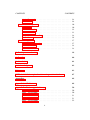

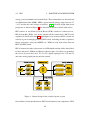

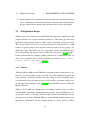
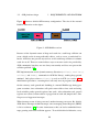
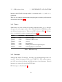
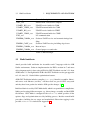
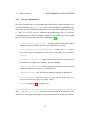
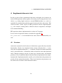
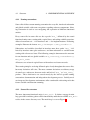
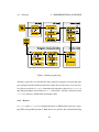
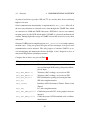
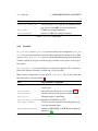
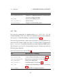
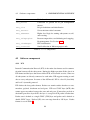
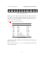
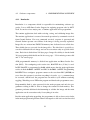
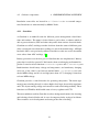
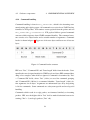
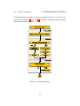
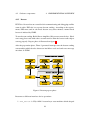
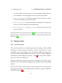
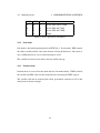

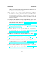
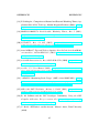

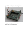
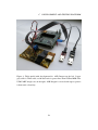
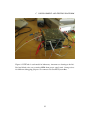
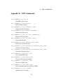
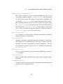
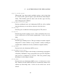
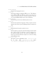


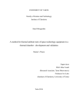


![Forms [packet] specific to Licensed Child Care](http://vs1.manualzilla.com/store/data/005750447_1-ace0dbf587046d14d311f9d21e5da3df-150x150.png)