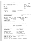
1
STA PULLOUT User Manual
January 29, 1999
Page i
STA PULLOUT
ANCHOR PLATE PULLOUT RESISTANCE
Version 1.1, January 1999
USER MANUAL
STA PULLOUT is a computer program for the design and analysis of plate anchors. The program does
not consider how the plate may have been embedded. The pulling line attachment is assumed to be
arranged such that the line pull is perpendicular to the plate and the pulling force is directly above the
plate center of area.
STA PULLOUT permits the user to specify up to three different soil layers, each of which may have
varying strength properties. The layers may be a mixture of cohesive and cohesionless soils. Primary
results from the program provide the ultimate capacity of plate anchors for vertical pullout resistance.
The program provides factors of safety against failure for short term and long term loading. Resistance to
dynamic loading is also accounted for.
This program has been developed by Stewart Technology Associates (STA).
All copyright for the software and documentation remains with STA. Users of
the program are cautioned to exercise experienced and careful engineering
judgment when interpreting the results from STA PULLOUT. This is especially
important with this program, since results can be obtained in seconds on a
modern PC. This rapid speed and ease of use does not alter the care and
attention needed from the user associated with selecting the appropriate
geotechnical and loading conditions. The program runs in the environment of
Microsoft Windows and Microsoft Excel. A mouse is used to click on option
buttons in order to move rapidly through the analysis. A large number of Help screens are provided. No
experience of Excel is required to use STA PULLOUT.
No part of this document should be taken in isolation or out of context and interpreted in a manner
inconsistent with the overall framework and intent of this document.
STEWART TECHNOLOGY ASSOCIATES
5619 Val Verde
Houston, Texas 77057
Tel: (713) 789-8341
Fax: (713) 789-0314
e-mail: [email protected]
10/29/98
C:\Documents and Settings\Lucy.HAL-9000A\My Documents\My Web Sites\stewart-usa.com\www\STAPullout.doc
STA PULLOUT User Manual
January 29, 1999
Page ii
EXTRACTS FROM LICENSE AGREEMENT
1.
This License is granted to the USER for an indefinite period. The USER agrees that no
individual, outside consultant, government organization, or any person who is not on permanent
staff with the USER or under direct in-house control of USER shall have access to the
PROGRAM or shall use the PROGRAM for any purpose at any time. The use of the PROGRAM
is not limited to a single machine, and the USER may make copies of PROGRAM and run it on
several machines simultaneously. The USER agrees to make any reasonable effort to assure
that the PROGRAM file or disk is not copied without authorization by OWNER, and that all users
in USER's organization are familiar with these Limitations of Use. The USER agrees not to
modify, copy, sell, lease, rent, give free of charge, or otherwise distribute or alter the PROGRAM
or any part thereof to any individual, government agency, or organization outside of the USER
organization.
2.
All copyrights to the PROGRAM are reserved by OWNER. All versions of the PROGRAM are
copyrighted by OWNER worldwide, beginning with 1991. The following is a trademark of
OWNER: STA PULLOUT. The USER shall clearly and distinctly indicate the copyright in all
published and public references to the PROGRAM. The USER will abide by the Copyright Law
of the United States, with the exception that the USER can make as many copies of the
PROGRAM as deemed necessary by the USER and may run the PROGRAM simultaneously on
as many computers as deemed necessary by the USER.
5.
The USER will not prepare derivative works based on the PROGRAM provided under this
agreement without acknowledging Stewart Technology Associates (STA) as the original authors
of the PROGRAM. The USER will provide copies of any derivative works to STA within one
month of the USER completing any such derivative works.
4.
The OWNER will attempt to diagnose any problems associated with a defective diskette or a fault
found in the program. If a fault is thought to exist by the USER within the PROGRAM, the
OWNER will attempt to rectify the problem upon receipt of a full written explanation of the fault
from the USER.
5.
While the OWNER has carefully developed the PROGRAM and the PROGRAM has been tested
for accuracy and proper functioning, nevertheless the OWNER cannot guarantee its accuracy
and correctness. If the PROGRAM fails to perform correctly as a result of errors or omissions by
the OWNER or its staff, the OWNER will, at its discretion, rectify those errors and omissions free
of all charges to the USER. This shall be the limit of the OWNER's liability in this respect. The
OWNER warrants that it has the right to grant this license. The PROGRAM and its
documentation are sold "as is," and the USER assumes the entire risk as to quality and
performance.
6.
The cost for this PROGRAM is $xxx, including a single user manual. The PROGRAM may be
used on a network.
7.
Support services from Stewart Technology Associates for the use of the PROGRAM are included
in the purchase price of the original copy of the PROGRAM. These support services are for a
total period of xxx hours total consultancy time. If additional services are required beyond the xxx
hours noted above, such services will be charged at the rate of $xxx per hour.
8.
The OWNER shall not be liable to the USER or any other party for any design, performance or
other fault or inadequacy of the PROGRAM or its manual, or for any direct or implied damages of
any kind arising out of or in any way related to or connected with any use of the PROGRAM.
C:\Documents and Settings\Lucy.HAL-9000A\My Documents\My Web Sites\stewart-usa.com\www\STAPullout.doc
STA PULLOUT User Manual
January 29, 1999
Page iii
CONTENTS LIST
Subject
Page #
1.0
INTRODUCTION .................................................................................................. 1
2.0
FAILURE MECHANISM........................................................................................ 2
3.0
PROGRAM INSTALLATION................................................................................. 3
4.0
HARDWARE REQUIREMENTS AND PRINTING................................................. 5
5.0
RUNNING THE PROGRAM ................................................................................. 7
6.0
GETTING HELP ................................................................................................... 8
7.0
BASIC ANALYSIS ASSUMPTIONS.................................................................... 10
8.0
RESULTS ........................................................................................................... 12
REFERENCES .............................................................................................................. 13
APPENDIX 1 .....................................................................DEFINITION OF INPUT DATA
C:\Documents and Settings\Lucy.HAL-9000A\My Documents\My Web Sites\stewart-usa.com\www\STAPullout.doc
STA PULLOUT, VERSION 1.1, February 1999
1.0
PAGE 1
INTRODUCTION
STA PULLOUT is a computer program for the design and analysis of plate anchors. The
program does not consider how the plate may have been embedded. The original application
was developed for marine plate anchors embedded in the seabed and loaded vertically. STA
PULLOUT can be used to estimate the maximum force needed to recover a drag embedment
anchor. The program has also been used to solve onshore problems.
STA PULLOUT permits the user to specify up to three different soil layers, each of which may
have varying strength properties. The layers may be a mixture of cohesive and cohesionless
soils. Primary results from the program provide the ultimate capacity of plate anchors for
vertical pullout resistance. The program provides factors of safety against failure for short term
and long term loading. Resistance to dynamic loading is also accounted for.
C:\Documents and Settings\Lucy.HAL-9000A\My Documents\My Web Sites\stewart-usa.com\www\STAPullout.doc
STA PULLOUT, VERSION 1.1, February 1999
2.0
PAGE 2
FAILURE MECHANISM
Two general failure mechanisms are assumed by the program: shallow failure and deep
failure. These failure mechanisms are illustrated in Figure 1 below.
FIGURE 1
When computing plate pullout resistance, STA PULLOUT adjusts the bearing capacity
factors accounting for plate geometry, plate burial depth and soil properties.
C:\Documents and Settings\Lucy.HAL-9000A\My Documents\My Web Sites\stewart-usa.com\www\STAPullout.doc
STA PULLOUT, VERSION 1.1, February 1999
3.0
PROGRAM INSTALLATION
3.1
Introduction
PAGE 3
STA PULLOUT is a computer program for the design and analysis of pile anchors. The
latest release of the program (Version 1.5, October 1998) runs in the environment of
Microsoft Excel 97, or later, under Windows 95, NT4, or later. The program is
distributed as a series of Excel workbook with macro files on a single 3.5 inch floppy
disk.
This section of the manual provides instructions for loading the program and setting up
the Windows icon.
3.2
Install Files and Create Directories
STA PULLOUT must be set up in sub-directory on your hard disk. Before installing STA
PULLOUT, you must have Excel already installed on your hard disk. You must
manually set up the necessary directory and copy the files over. The manual procedure
is as follows:
Create a sub-directory, for example, called STAPULLOUT. All files from
the floppy disk should be copied into the STAPULLOUT sub-directory.
You will then have a path to the program files as shown below:
X:\MY_PROJECTS/STAPULLOUT/program_files
In the example above, X: is the name of your hard disk (most likely this will be C: or D:)
and the MY_PROJECTS directory may be where you store your projects.
3.3
Install Icon
Once the directory structure has been created and the program files have been copied
from the distribution floppy diskette to the STAPULLOUT sub-directory, you can set up
the icon (see your Windows documentation, or simply right-click on your desktop and be
intuitive).
3.4
Program Files On Distribution Diskettes
Each distribution diskette for STA PULLOUT is a self-contained version of the program.
The files on your diskette should be as listed below.
C:\Documents and Settings\Lucy.HAL-9000A\My Documents\My Web Sites\stewart-usa.com\www\STAPullout.doc
STA PULLOUT, VERSION 1.1, February 1999
File Name
STAPULLOUT.ICO
STAPULLOUT.XLS
PAGE 4
Description
Icon for STA PULLOUT. The icon is displayed by Windows. Double
click on the icon to start STA PULLOUT after program is installed.
This is the main file displayed to the user by Excel. All the data input
is specified in this file. All principle results are contained in this file.
Other files may be present on your diskette, and the names of some of the above files
may be changed slightly on some diskettes.
The STA PULLOUT icon is shown to the right.
C:\Documents and Settings\Lucy.HAL-9000A\My Documents\My Web Sites\stewart-usa.com\www\STAPullout.doc
STA PULLOUT, VERSION 1.1, February 1999
4.0
PAGE 5
HARDWARE REQUIREMENTS AND PRINTING
STA PULLOUT requires an IBM PC with Microsoft Excel 67 or later, running under
Microsoft Windows 95 or later environment. Program output has been customized such
that it prints all principal input and output on one page as shown in Figure 2, on the
following page.
For best quality print, it is recommended that a color ink jet printer be used with a
minimum resolution of 300 dpi. Significantly better quality will be obtained with a dot
resolution of 400 dpi or above.
True Type fonts have been used throughout the worksheet. Almost all the fonts are
Arial. Many of the fonts are Arial Narrow. If you do not have these fonts on your
machine, the program will select the nearest font style. It is recommended that you
obtain the Arial Narrow font if it is not currently available on your system.
You may elect to print any of the output in color, for example on a HP Deskjet printer. If
a color printer is used, you may have to disable certain third party fontware, such as
Adobe Type Manager, in order to get color text and numbers to print. However, once
your printer is set up to print any other spreadsheets from Excel, you should have no
problem in printing output from STA PULLOUT.
You may have a higher resolution screen driver (than VGA, which is the minimum
required for STA PULLOUT) in use on your system. This will be advantageous in that it
allows you to see more of the main worksheet than you can see with a VGA driver.
Most of the examples in this manual show screens with an 800 x 600 screen driver.
C:\Documents and Settings\Lucy.HAL-9000A\My Documents\My Web Sites\stewart-usa.com\www\STAPullout.doc
STA PULLOUT, VERSION 1.1, February 1999
STA PULLOUT
PAGE 6
Anchor Vertical Pullout Resistance
v.1.0 May 1993
Run ref: Example For User Manual
2/8/99 9:11
Copyright Stewart Technology Associates 1993. For support telephone: (713) 665-7294, or fax: (713) 665-1424
Assumptions
Explain
Permeability & Plasticity for Cyclic Loading
Print this screen
INPUT DATA BELOW
SOIL PROPERTIES
ANCHOR PROPERTIES & ANALYSIS CONTROL
100.00 Z1, thickness of upper soil layer (ft)
7.00 fluke length (ft)
0.8
Strength reduction factor
7.00 fluke width (ft)
200
av.static uplift load (kips)
44.10 fluke area (sqft)
77
dynamic load double amp. (kips)
140.00 burial depth (ft)
2
1=cohesionless, 2=cohesive
1
1=normal, 2=delta mud
50.00 Z2, thickness of middle soil layer (ft)
5.00 Z3, thickness of lowest soil layer (ft)
35.00 cu1, undrained sh. strength top 1st layer (psf)
835.00 cu2, undrained sh. strength bottom 1st layer (psf)
12.00 storm duration (hours)
885.00 cu3, undrained sh. strength top 2nd layer (psf)
12.00 av.wave period (sec)
910.00 cu4, undrained sh. strength bottom 2nd layer (psf)
Soil Shear Strength Profile
910.00 cu5, undrained sh. strength top 3rd layer (psf)
920.00 cu6, undrained sh. strength bottom 3rd layer (psf)
0.00
22.00 drained friction angle 1st layer (deg)
-20.00
32.00 drained friction angle 3rd layer (deg)
-40.00
35.00 Gamma1, 1st layer buoyant weight (pcf)
-60.00
73.00 Gamma2, 2nd layer buoyant weight (pcf)
30.00 Gamma3, 3rd layer buoyant weight (pcf)
0 ratio of drained/undrained soil cohesion
Results
Short-term ultimate capacity (kips)
Long-term ultimate capacity (kips)
Static short-term safety factor
Static long-term safety factor
Holding Capacity Factors at Anchor
479
479
2.39
2.39
depth in feet
27.00 drained friction angle 2nd layer (deg)
-80.00
-100.00
-120.00
anchor
-140.00
-160.00
-180.00
0
200
400
600
800
undrained shear strength in psf
15.00 Ncs short-term (calculated)
9.50 Nc long-term (calculated)
8.37 Nq cohesionless (calculated)
Dynamic Loading Parameters
0.003 estimated soil permeability (ft/sec)
0 time reqd.for pore press.dissipation (days)
2.63 dynamic load range safety factor (single storm)
202 maximum dynamic load range for single storm (kips)
12 number of loading cycles in single storm
FIGURE 2
C:\Documents and Settings\Lucy.HAL-9000A\My Documents\My Web Sites\stewart-usa.com\www\STAPullout.doc
1000
STA PULLOUT, VERSION 1.1, February 1999
5.0
PAGE 7
RUNNING THE PROGRAM
Once you have set up the program using the instructions in Section 4.0, you will be able
to click on the STAPULLOUT icon to start Excel and STA PULLOUT. The main
spreadsheet (STAPULLOUT.XLS) will load. You may need to
maximize the spreadsheet. Do this by clicking once on the middle
symbol in the upper right hand corner of the spreadsheet as shown
in the figure on the right.
The spreadsheet will always contain values in every editable cell. It is recommended
that following an analysis with the program, you save the spreadsheet before closing
down the application.
You may also want to set Excel calculations to automatic. You do this through the
Tools, Options, menus.
C:\Documents and Settings\Lucy.HAL-9000A\My Documents\My Web Sites\stewart-usa.com\www\STAPullout.doc
STA PULLOUT, VERSION 1.1, February 1999
6.0
PAGE 8
GETTING HELP
In Figure 2, two of the buttons are labeled Explain . Highlight any data entry or results
cell (by clicking on it once) and then click once on any Explain button. A dialog box
will be flashed up onto the screen containing information regarding the selected cell. An
example of this is shown in Figure 3. In this figure, the user has selected the input cell
strength reduction factor. A dialog box has been brought up onto the screen describing
what this input data does.
FIGURE 3
Help is also available in interpreting the results. The main summary results for an
installed pile analysis are seen in the lower right hand corner of Figure 2.
If the user selects a cell for which there is no help available, a dialog box will be flashed
up on the screen, suggesting that the cursor be repositioned in another cell. An
example of this is shown in Figure 4.
C:\Documents and Settings\Lucy.HAL-9000A\My Documents\My Web Sites\stewart-usa.com\www\STAPullout.doc
STA PULLOUT, VERSION 1.1, February 1999
PAGE 9
FIGURE 4
C:\Documents and Settings\Lucy.HAL-9000A\My Documents\My Web Sites\stewart-usa.com\www\STAPullout.doc
STA PULLOUT, VERSION 1.1, February 1999
7.0
PAGE 10
BASIC ANALYSIS ASSUMPTIONS
The user can be reminded of the basic analysis assumptions when running the program
by clicking once on the button assumptions.
STA PULLOUT uses the geotechnical formulae and nomenclature of the NCEL
Geotechnical Handbook. The user should have the Handbook at the ready when using
the program, especially if the dynamic soil properties are of interest.
7.1
Permeability and Plasticity for Cyclic Loading
In accordance with the procedures in the NCEL Geotechnical Handbook, the user can
select a soil characterization from the dialog box shown in Figure 5. This box appears
when the button Permeability and Plasticity for Cyclic Loading is clicked.
FIGURE 5
After selecting one of the soil types, click OK and the program will display the dialog box
shown in Figure 6, indicating the maximum soil cyclic load capacity without causing soil
loss of strength.
C:\Documents and Settings\Lucy.HAL-9000A\My Documents\My Web Sites\stewart-usa.com\www\STAPullout.doc
STA PULLOUT, VERSION 1.1, February 1999
PAGE 11
FIGURE 6
Layered Soils
Up to three soil the user in STA PULLOUT can specify layers which may be mixed
cohesive and cohesionless layers. In each layer, the above equations are implemented
for each elemental length of the pile. Overburden pressure is calculated for buried
cohesionless layers.
C:\Documents and Settings\Lucy.HAL-9000A\My Documents\My Web Sites\stewart-usa.com\www\STAPullout.doc
STA PULLOUT, VERSION 1.1, February 1999
8.0
PAGE 12
RESULTS
The pullout resistance results are shown in the bottom left hand corner of Figure 2. A
larger view is shown in Figures 7 and 8.
Results
2370 Capacity in cohesionless soil (kips)
cohesionless soil selected
11.85 Static short-term safety factor
FIGURE 7
Results
479
479
2.39
2.39
Short-term ultimate capacity (kips)
Long-term ultimate capacity (kips)
Static short-term safety factor
Static long-term safety factor
FIGURE 8
Results in Figure 7 are for a cohesionless soil. Results in Figure 8 are for a cohesive
soil.
C:\Documents and Settings\Lucy.HAL-9000A\My Documents\My Web Sites\stewart-usa.com\www\STAPullout.doc
STA PULLOUT, VERSION 1.1, February 1999
PAGE 13
REFERENCES
1.
"Handbook For Marine Geotechnical Engineering", Technical Editor, Rocker, K.
March 1985, available from Naval Civil Engineering Laboratory Port Hueneme,
California 93043.
C:\Documents and Settings\Lucy.HAL-9000A\My Documents\My Web Sites\stewart-usa.com\www\STAPullout.doc
STA PULLOUT, VERSION 1.1, February 1999
Appendix 1 - PAGE 1
APPENDIX 1
DEFINITION OF INPUT DATA
This Appendix lists each of the input data terms that the user may edit. Note that by
placing the cursor on any input data cell and clicking on the button, EXPLAIN VALUE,
the User is presented with a dialog box containing a detailed description of the input
data term. This Appendix provides a reference for each of these terms.
C:\Documents and Settings\Lucy.HAL-9000A\My Documents\My Web Sites\stewart-usa.com\www\STAPullout.doc
STA PULLOUT, VERSION 1.1, February 1999
Appendix 1 - PAGE 2
Z1, thickness of upper soil layer (ft)
This is the thickness of the first soil layer from the sea bed downwards. Units are feet.
Z2, thickness of middle soil layer (ft)
This is the thickness of the second soil layer beneath the seabed. Units are feet. Note
that a visual check on the input data is provided in the upper diagram on the main
results page for the program entitled, Soil Shear Strength Profile.
Z3, thickness of lowest soil layer, (ft)
This is the thickness of the lowest soil layer in the analysis. Units are feet. Note that if
the plate is defined as being embedded to a depth within the sea bed beneath the
bottom of this lowest soil layer, the properties for the soil at the bottom of the layer will
be extended to the plate location.
Phi1, 1st layer friction angle (deg.)
This is the friction angle to be used in the analysis for cohesionless soil in the first layer.
Units are degrees. If the first soil layer is cohesive, Phi1 should be specified as zero.
The program will issue a warning if both cohesive and cohesionless properties are
specified for any soil layer.
Phi2, 2nd layer friction angle (deg.)
This is the friction angle to be used in the analysis for the second soil layer. Comments
as for Phi1 apply.
Phi3, 3rd layer friction angle (deg.)
This is the third layer friction angle. Comments as for Phi1 apply.
cu1, undrained sh. strength top 1st layer (psf)
This is the UNDISTURBED undrained shear strength for the soil at the top of the first
layer, in other words, at the seabed. Units are in pounds force per square foot.
cu2, undrained sh. strength bottom 1st layer (psf)
This is the UNDISTURBED undrained shear strength for the soil at the bottom of the
first layer, in other words, at the seabed. Units are in pounds force per square foot.
The undrained shear strength is considered to vary in a linear manner between the top
and bottom of each layer.
cu3, undrained sh. strength top 2nd layer (psf)
This is the undrained shear strength for the soil at the top of the second layer, in other
words, at the seabed. Units are in pounds force per square foot.
cu4, undrained sh. strength bottom 2nd layer (psf)
Comments as for cu2 apply.
cu5, undrained sh. strength top 3rd layer (psf)
Comments as for cu1 apply.
C:\Documents and Settings\Lucy.HAL-9000A\My Documents\My Web Sites\stewart-usa.com\www\STAPullout.doc
STA PULLOUT, VERSION 1.1, February 1999
Appendix 1 - PAGE 3
cu6, undrained sh. strength bottom 3rd layer (psf)
Comments as for cu2 apply. Note that if the pile is specified as being embedded with its
bottom beneath the third soil layer, the soil strength and weight parameters at the
bottom of the third layer will be continued downwards.
Gamma1, 1st layer buoyant weight (pcf)
This is the submerged, or buoyant weight of the soil in the first layer. Units are in
pounds per cubic foot.
Gamma2, 2nd layer buoyant weight (pcf)
This is the submerged, or buoyant weight of the soil in the second layer. Units are in
pounds per cubic foot.
Gamma3, 3rd layer buoyant weight (pcf)
This is the submerged, or buoyant weight of the soil in the third layer. Units are in
pounds per cubic foot.
fluke length (ft)
This is the maximum length of the plate
fluke width (ft)
This is the maximum width of the plate
Fluke area (sqft)
This is the actual area of the plate and does not have to be equal to the length times the
width as the plate does not have to be rectangular.
Burial Depth (ft)
The depth beneath the seabed where the plate is located. If a keying operation is to
take place, as with a driven plate anchor, this should be the depth after keying.
Storm duration (hours)
If dynamic information on plate behavior is required, this is the duration of a design
storm.
Av.wave period (sec)
If dynamic information on plate behavior is required, this is average period of the waves
in the design storm and can be set equal to the average zero-crossing period.
Strength reduction factor
This term is used to multiply the undisturbed undrained shear strength of each layer. A
reduction factor of 0.5 means that the actual undrained strength of the soil used in
resistance and pullout calculations will be 50% of that input by the User. A reduction
factor of 0.75 means that the actual undrained shear strength of the soil will be 75% of
that specified by the User.
C:\Documents and Settings\Lucy.HAL-9000A\My Documents\My Web Sites\stewart-usa.com\www\STAPullout.doc
STA PULLOUT, VERSION 1.1, February 1999
Appendix 1 - PAGE 4
Av.static uplift load (kips)
This is the design load required by the user. If dynamic loads are also considered, this
should be the average load, normally equal to the static component only.
Dynamic load double amp. (kips)
If dynamic loading is considered this should generally be equal to the significant load in
a storm. More conservatively, it can be set equal to the maximum anticipated load.
1=cohesionless, 2=cohesive
This is a switch that must be set by the user. If all layers are cohesionless select 1.
Otherwise select 2 and use the long-term pullout resistance results if the plate is in a
cohesionless layer.
1=normal, 2=delta mud
This is a switch that must be set by the user. The switch function is explained below.
C:\Documents and Settings\Lucy.HAL-9000A\My Documents\My Web Sites\stewart-usa.com\www\STAPullout.doc