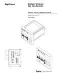
1
SM-5 Striping System Installation and Operation CAUTION READ BEFORE INSTALLING! 2 Table of Contents INTRODUCTION ..................................................................................................................................... 5 SYSTEM OVERVIEW .............................................................................................................................. 5 INSTALLATION ....................................................................................................................................... 6 Precautions: ...................................................................................................................................................... 6 Mounting Information: .................................................................................................................................. 6 Wiring: ................................................................................................................................................................ 6 SM-‐5 STANDARD FEATURES ............................................................................................................. 7 AutoCycle: .......................................................................................................................................................... 7 Delay1: ................................................................................................................................................................ 7 Bead Registration: .......................................................................................................................................... 7 Standard Switches/Features: ...................................................................................................................... 7 Advance/Retard (ADV/RET) ..................................................................................................................................... 7 Alternate Cycle (ALT) .................................................................................................................................................... 7 BEADS .................................................................................................................................................................................. 7 CARRIAGE ........................................................................................................................................................................... 7 Gun Control Switches (1, 2, 3, etc.) .......................................................................................................................... 7 START/STOP ..................................................................................................................................................................... 8 HOLD/MARK ..................................................................................................................................................................... 8 SYSTEM CONFIGURATION .................................................................................................................. 8 Entering Calibration Mode: ......................................................................................................................... 8 Activating AutoCycle: ..................................................................................................................................... 8 Adjusting Bead Registration: ...................................................................................................................... 8 Activating Delay1: ........................................................................................................................................... 9 Footage Calibration: ....................................................................................................................................... 9 Footage Counter Operation: ........................................................................................................................ 9 To Select Channels: ......................................................................................................................................................... 9 To Reset One Channel: ............................................................................................................................................... 10 To Reset All Channels Simultaneously: .............................................................................................................. 10 Memory: ........................................................................................................................................................................... 10 Gallons Calibration: ...................................................................................................................................... 10 Speedometer Calibration: .......................................................................................................................... 11 Stripe and Cycle Length: ............................................................................................................................. 11 Gun Factor: ...................................................................................................................................................... 11 Example: ........................................................................................................................................................................... 12 Tips:.................................................................................................................................................................................... 12 OPTIONAL SYSTEM FEATURES ...................................................................................................... 13 Black Paint: ..................................................................................................................................................... 13 Shadow Black: ................................................................................................................................................................ 13 Auto Black: ...................................................................................................................................................................... 13 Spotter Option: ............................................................................................................................................... 13 Mid-‐Spot Option: ........................................................................................................................................... 14 Profile Adjustment: (Thermoplastic Systems Only) ......................................................................... 14 Optional Switches/Features: ..................................................................................................................... 14 3 AIR ...................................................................................................................................................................................... 14 GUN RAISERS ................................................................................................................................................................. 14 REMOTE ........................................................................................................................................................................... 14 VISILOK® ........................................................................................................................................................................ 15 WITHHOLD ..................................................................................................................................................................... 15 ZIPPER .............................................................................................................................................................................. 15 LIMITED WARRANTY ........................................................................................................................ 16 4 INTRODUCTION This manual provides the necessary information to properly install and operate the SM-5 striping system. Also, this manual provides information on optional features that may not be included with your system. SYSTEM OVERVIEW Typically, the system will include (2) SM-5 masters and (1) SM-5 slave box. What is included in the system depends on what was ordered. The SM-5 system can be ordered with additional controllers to meet specialized needs. These boxes are connected using the RJ12 jack on the front of the slave unit and the rear of the master unit. These ports are parallel, meaning there is no correct or incorrect port for each box to communicate to the other. (Master Box) (Master Box) (Slave Box) 5 INSTALLATION Precautions: • • • THIS EQUIPMENT IS FOR 12 VOLT NEGATIVE GROUND SYSTEMS ONLY! Do not connect to positive ground systems or damage will result! The SLAVE BOX MUST BE PHYSICALLY GROUNDED before use! Mounting Information: All SM-5 units have threaded inserts on each side to facilitate mounting. Fabricate a suitable "U" bracket to firmly support the timer. Please use the (2) 1/4inch diameter coarse thread hex bolts provided with the unit. If substitutions are necessary, be sure the mounting bolts do not penetrate more than 1/2 inch into the threaded inserts. Long bolts may damage internal components. • • • • Avoid locations that are exposed to excessive vibration, direct sunlight, moisture, and extremes of temperature. Be sure to allow room for the cable to plug in at the rear of the timer. Be sure to use a fuse in the 12-volt supply wire. Typical solenoids draw about 1 ampere, so a 5-20 ampere fuse will protect the wiring from short circuits. All output connections apply a ground when turned on. Note: The SM-5 system is not waterproof. A waterproof box or cover must protect outboard installations. Such enclosures need a small vent to prevent moisture accumulation. PLEASE NOTE: Each of the Operator Control stations (Master Units) is identical and interchangeable. Each is configurable to control all of the paint functions on one side of the truck or the other. Each Master box communicates the set up information via the telephone cable to the Slave unit which activates the corresponding solenoids. Depending on the system, configure the Control Box as a “Left Box” or “Right Box” with the slide switch located on the rear of each Control Box, or by entering calibration mode and assigning the box to be a Left box or Right box. Follow instructions under Entering Calibration Mode on how to navigate the menu and how to select the desired configuration. WARNING Two boxes on the same vehicle MUST NOT be configured for the same side of the truck. The two units will send conflicting data to the slave unit. This may result in unpredictable activation of the solenoids. All telephone jacks on the system are connected together internally, so it makes no difference which telephone connection is used on each box, as long as all boxes are connected together. Wiring: The green connectors on the SM-5 slave unit are removable for. Refer to page 4a for the specific wiring diagram for this system. 6 SM-5 STANDARD FEATURES AutoCycle: AutoCycle is a special aid for repainting old work. The AutoCycle system invokes an automatic cycle correction feature that adjusts the cycle length automatically when the computer detects that the operator is frequently favoring either advance or retard (ADV/RET)*. The cycle will change in such a manner as to cause less frequent need for manual advance or retard corrections. The advance and retard controls displace the entire pattern forward or backward on the pavement to register the new paint with the old. *AutoCycle is adjusted using the advance/retard switch (ADV/RET). Refer to standard switches/features. Delay1: DELAY1 is a feature that delays the first stripe to allow full coverage by the glass beads. The first stripe delay is automatically adjusted once the bead registration has been set. This is explained in the system configuration section. Bead Registration: Bead registration is a system to help position the beads over the paint pattern. The edges of the bead pattern can be moved relative to the paint pattern. This helps to ensure the beads are applied to the full paint pattern. Standard Switches/Features: Advance/Retard (ADV/RET) The advance and retard controls are used when repainting previously painted highways. The advance and retard controls displace the entire pattern forward or backward on the pavement to register the new paint with the old. Hold the ADV control in the UP position a moment to shift the pattern forward on the pavement. The RET control shifts the pattern backward. The longer each control is held, the greater the pattern displacement. When not in motion this control has no effect. Alternate Cycle (ALT) The ALT switch is for selecting between two or three different paint patterns depending on how the system was ordered. This enables you to have two or three separate stripe and cycle length settings available. To use alternate cycle, simply enter the stripe and cycle length on the display, then flip the ALT switch and enter in a new pattern on the alternate display. Now you have multiple patterns to select between with this control switch. BEADS The BEADS switch turns the bead guns off independently of the paint guns. CARRIAGE The CARRIAGE switch raises or lowers the paint carriage. Gun Control Switches (1, 2, 3, etc.) These switches control the gun solenoids directly. In the UP position the gun will be in the SOLID mode, or painting solid lines. In the CENTER position, the gun is in the "OFF" position. In the DOWN position the gun is in the SKIP pattern mode. 7 In the "SKIP" position, the skip-timer controls the paint gun solenoid and turns it ON and OFF according to the pattern that is set in the skip-timer display. START/STOP The START switch acts as a systems reset. When in the STOP position, all guns are off, and the skip-timer is at an initialized or reset state. When placed in the START position, any preselected gun will turn on. If one gun is in the skip position then the skip-timer will be activated to generate the skip pattern starting with a stripe. HOLD/MARK In the HOLD position, all paint and bead guns are turned off, while the skip pattern continues to cycle. In the MARK position, all SKIP guns are disabled, SOLID guns continue to paint. The SKIP gun will continue to paint when the MARK switch is released. SYSTEM CONFIGURATION This section explains the setup process of standard features. Optional features setup will be listed with the description under OPTIONAL SYSTEM FEATURES. Entering Calibration Mode: With the START switch in the STOP position, press the TIMER and RESET switches up simultaneously. A series of questions will appear on the display. To answer the questions, press the CYCLE switch up to select Yes, and down to select No (Y/N), then press the STRIPE switch down to enter the answer. Activating AutoCycle: To activate AutoCycle, follow the instructions for entering the calibration mode, and select "Yes" when the question "AUTOCYCLE (Y/N)" appears on the display. Selecting “No” when the question “AUTOCYCLE (Y/N)” appears will deactivate the “AUTOCYCLE” feature. AutoCycle is controlled using the advance/retard switch (ADV/RET). Adjusting Bead Registration: The (+) and (-) refer to the switches labeled BEGIN and END under BEADS. These switches are typically located on the top row of the master box. Adjustments described are made using these switches. The system will show the bead registration display once one of these switches has been pressed. The BEGIN control affects the "turn on" part of the bead pattern. The END control affects the "turn off" part of the bead pattern. The numbers on the display represent tenths-of-a-foot adjustments. (+) Will move the beads forward on the pavement. (-) Will move the beads backwards on the pavement. The correction is not perfect; it depends on speed and agility of your paint guns. 8 |< < - Beginning + > Stripe < - >| END + > Direction of Motion > Bead registration overlay correction at the beginning and end of the stripe. The Transparent blue represents the application area of the beads. Activating Delay1: To activate the "DELAY1" feature, follow the instructions for entering the calibration mode, and select "Yes" when the question "DELAY1 (Y/N)" appears on the display. Selecting “No” when the question “DELAY1 (Y/N)” appears will deactivate the “DELAY1” feature. Footage Calibration: Before entering the calibration mode, make sure the TRUCK FOOTAGE counter has been RESET to zero. Travel a known distance (1000 feet min.) with the START switch in the START position. A number will be recorded in the TRUCK FOOTAGE counter. Now enter the calibration mode. When the question, "SET CAL? (Y/N)" appears, select Y using the CYCLE switch, and enter the answer using the STRIPE switch. Two numbers will appear on the display. The top number is the calibration number (nominal setting is 0.1000). The bottom number is the distance the truck traveled with the START switch on. To adjust the calibration, change the distance number using the CYCLE switch until the distance number reads what the vehicle actually traveled with the START switch on. As the distance number is changed, the calibration number will also change. To save the calibration number, press the STRIPE switch down, and exit the calibration mode by answering the remaining questions. NOTE: The calibration memory is limited to a number between 0.1500 and 0.0500. The computer cannot remember any number outside of this range. Footage Counter Operation: The TIMER/COUNTER and RESET/CLEAR switches control all functions of the footage counter. To Select Channels: To select the individual channels, push the COUNT Switch DOWN to change the channels. There are eight channels, each marked for a particular gun. Normal channel assignments are as follows: 9 Channel 1 is a counter for control switch #1 on the left side. " 2 is a counter for control switch #2 " 3 is a counter for control switch #3 " 4 is a counter for control switch #4 " " " " 5 is a counter for control switch #1 on right side 6 is a counter for control switch #2 7 is a counter for control Switch #3 8 is a counter for control Switch #4 The ODOMETER channel counts whenever the START switch is on and the vehicle is moving. All channels continue to count regardless of which channel is being displayed. To Reset One Channel: Push the "RESET" switch UP. The currently displayed channel goes to zero. To Reset All Channels Simultaneously: Push the CLEAR switch and hold it there for 2 or 3 seconds.* All channels will clear. • NOTE: This delay time in clearing is a safety feature so all channels won't be reset accidentally. Memory: There are no internal batteries to worry about. It is prudent to regularly log readings to guard against accidental or unauthorized erasure. Accidental erasure is possible if unreasonable voltage surges occur on the 12-volt power line. The counter remembers all readings when the power is off, even if unplugged from its wiring harness! Gallons Calibration: To calibrate the GALLONS counters, follow the instructions for entering the calibration mode. When the words "SET YEL? (Y/N)" appear select Yes using the CYCLE switch and enter the answer using the STRIPE switch. A number will appear on the display. This calibration number represents tenthousandths of a gallon per stroke of the pump. EXAMPLES: • • If the pump displaces .25 gallons per stroke, set the gallons calibration number at 2500 using the CYCLE switch, and enter the number into memory using the STRIPE switch. If the pump displaces .075 gallons per stroke, set the gallons calibration number at 750. Next, the words "SET WHT? (Y/N)" appear. Follow the instructions above for setting the gallons calibration for the White pump. *Note: The gallons calibration number is valid from 250 to 9999. 10 Speedometer Calibration: The speedometer is automatically calibrated when the Skip-Timer is calibrated properly. Stripe and Cycle Length: CYCLE and STRIPE LENGTH controls may be adjusted at any time, in motion or at rest. To Adjust Stripe Length: • • STRIPE switch UP to increase, or lengthen the stripe. STRIPE switch DOWN to decrease, or shorten the stripe. The skip-timer displays and is calibrated for one-tenth-of-a-foot nominal resolution. In other words, the dial can alter the paint pattern by approximate one-tenth-of-a-foot increments. The STRIPE LENGTH will probably need to be set shorter than the desired paint pattern, because most paint guns respond more quickly to turn "on" than "off". They "hang on" and squirt a little longer paint pattern than the electrical system commands. The "hanging on" also causes some variation in stripe length with truck speed. The effect will be most evident at high truck speed. NOTE: If a paint gun hangs on for .050 second, the error will be 1.1 foot at 15 mph. To Adjust Cycle Length: • • CYCLE switch UP to increase or lengthen the repeat pattern. CYCLE switch DOWN to decrease or shorten the repeat pattern. The cycle is measured from the BEGINNING of one stripe to the BEGINNING of the next stripe. < Stripe < > < Cycle Length Stripe > > The CYCLE adjustment is calibrated in one-tenth-of-a-foot increments. Since the CYCLE pattern is measured from a point where the paint gun turned "on" to a point where it turned "on" again, there is no unbalanced "hang" effect. If the truck is not accelerating, the paint displacement caused by gun delay should be similar for the first and second stripes painted at a given speed. Therefore, the CYCLE is not dependent on truck speed. Gun Factor: Gun Factor is a time compensation for the inherently slow turn-off speed of paint guns and solenoids. Setting a number in Gun Factor delays the turn-on time of the paint gun in milliseconds. The turn-off time of a paint gun can be calculated as follows: 11 • • • • • • Calibrate the skip-timer system on a 1000 ft. minimum course. (If more than one box, both should have the same cal. #)(When calibrated correctly, the CYCLE length should be equal to the displayed CYCLE length.) Set the displayed STRIPE length to a desired length. Paint several stripes at a known speed. Measure the stripes. Subtract the displayed stripe length in feet from the measured stripe length. Divide the difference by the vehicle speed as striped in ft./sec. Example: • • • • • • Calibrate the skip-timer. Set the displayed STRIPE length to 10.0 Paint 3 skips at 12 MPH (17.6 ft./sec) Measured skip length is 10.8 ft. Subtract 10.0 ft. from measured 10.8 ft. = 0.8 ft. Divide 0.8 ft. by 17.6 ft./sec = 0.045 seconds The turn-off time of that paint gun is approximately 0.045 seconds • • • Set the GUN FACTOR number to 45 (45 milliseconds) Again paint 3 skips set at 10.0 ft. going 12 mph. The measured skips should be very close to 10.0 ft. If they need further adjustment, an increase in the GUN FACTOR # will shorten the stripe, and a decrease will lengthen the stripe. Here are a few speeds converted to ft./sec. 60 MPH = 5280 ft./min. = 88 ft./sec. 30 MPH = 44 ft./sec. 20 MPH = 29.33 ft./sec. 15 MPH = 22 ft./sec. 10 MPH = 14.67 ft./sec. 5 MPH = 7.33 ft./sec. Some advantages of accurately setting the GUN FACTOR number are: • The Footage counters will more accurately measure skips. • The stripe length will not change with vehicle speed. • The Bead registration will be more effective for matching paint and beads. Tips: • • • • • • The best striping performance will be realized when the paint guns and solenoids are as responsive as possible (This means the GUN FACTOR # will be minimal). The speed of the paint guns and solenoids can be increased with quick release valves on the paint guns. (To reduce the turn-off time of the paint gun, the solenoid dumps its air pressure more quickly) Adjustment to the spring tension on the paint gun can have a drastic effect on stripe length. o Too tight will cause the gun to turn on slowly, decreasing measured stripe length. o Too loose will cause the gun to turn off slowly, increasing measured stripe length. Multiple guns should be adjusted so that they turn on and off together, ideally the skip lengths should be longer, rather than shorter. New guns, and newly re-packed guns take a little time to loosen up. Generally, a wellused gun will be quicker than a brand new one. Hose lengths should be kept to a minimum. 12 OPTIONAL SYSTEM FEATURES Black Paint: Shadow Black: The shadow black feature is adjusted using the black switch. Turn the Black switch to ON and the black guns will stay on as long as the START switch is ON. If the Black switch is set to SHADOW, and the paint gun is set to SKIP, then the black guns will paint a given distance from 0-20 feet after the paint gun stops. The distance adjustment is made using the BLACK ADJUST switch. The black paint will not come one if you have the Black switch set to SHADOW and the paint gun set to SOLID. Black Paint Offset (Shadow Black): From the menu, set the distance offset between the white gun and the black as measured on the gun carriage in inches. Adjust the black paint offset until the black gun starts at the end of the white line without overlap. Auto Black: The Auto Black feature is used to paint a black line between two other lines. The black paint gun position is determined by how the system was ordered. In order for the black paint to work, the paint gun switches on each side of the black paint gun need to be on and in skip or solid. If you have a solid on one side of the black gun, and a skip on the other, the black paint will follow the skip pattern. This feature is used to visually enhance the white or yellow paint. Spotter Option: To enter the "SPOTTER" Mode, follow the instructions for entering the calibration mode. When the words "SPOTTER? (Y/N)" appear, select YES with the CYCLE switch, and enter the answer using the STRIPE switch. Next the word "SPOTS" and a number appear. Using the CYCLE switch, select the number of spots you want per stripe. You can select from 2 to 9 spots. Once you have selected the number of spots, push the STRIPE switch DOWN to set that number into memory. Next the word "LENGTH" and a number appears in the display. This number represents the spot length. Set this number by using the CYCLE switch. The range is from .2 to .9 feet. (You will have to experiment with this number to find what works best with the paint gun you are using.) Once this number is selected, save it by pushing the STRIPE switch DOWN. Next the word "MIDSPOT? (Y/N)" appears. With this ON, the skip-timer will place a spot in the center of the gap between stripes for the lane mark reflector. Answer YES or NO with the CYCLE switch and enter it with the STRIPE switch. Once all of the settings are saved, the skip-timer will do all the calculating to get the right spacing between spots. This can be done at rest or in motion. All BEAD REGISTRATION controls (LEAD/LAG) for beads, will be disabled while in the spotter mode. Only the paint will be used for marking. 13 Mid-Spot Option: Mid-Spot option is a feature that allows the system to place a paint spot indicator between two stripes. This creates a paint spot to indicate the placement of a raised marker. This feature is activated using the calibration menu. See “Entering Calibration Mode” listed under the SETUP section. Profile Adjustment: (Thermoplastic Systems Only) To adjust the PROFILE settings the PROFILE switch must be turned on before entering the calibration mode. With the PROFILE switch in the "ON" position, and the START switch off, enter the calibration mode by pressing the TIMER and RESET switches up simultaneously. An additional set of questions will appear in the calibration menu. To answer the questions, press the CYCLE switch up to select Yes, and down to select No (Y/N), then press the STRIPE switch down to enter the answer. Also use the CYCLE switch to adjust the profile settings, and the STRIPE switch to enter the answer. 1st PROFILE question: SET PROFILE? Or SET PRO? Answer Yes to adjust the Profile settings. Answer No to skip adjustments to Profile settings. 2nd PROFILE question: SPACE This number is the distance from one Profile bump to the next. The SPACE number has a range from 1.0 ft. to 11.0 ft. (All distances are in tenths-of-a-foot.) 3rd PROFILE question: LENGTH This number is the length of the actual Profile bump. The LENGTH number has a range from 0.1 ft. to 0.9 ft. (All distances are in tenths-of-a-foot.) 4th PROFILE question: INDENT This number is the offset from the beginning of a skip to the first Profile bump. The INDENT length has a range from 0.0 ft. to 0.9 ft. (all distances are in tenths-of-a-foot.) Optional Switches/Features: Optional switches may or may not be installed on this system. However, if the system does have an optional switch installed, a description of its function can be found below. AIR The AIR switch is used to control the air guns. In on, the air guns are on always as long as the system has power. In off, the air guns are all off. In auto, the air guns will follow the pattern determined by the gun switch. GUN RAISERS The GUN RAISER switches are used to raise and lower the individual paint guns. REMOTE With the switch in the SEMI position, any selected skip pattern responds only to the hand-held pushbutton. Each press of the button generates one full stripe, according to the STRIPE length selected. 14 In the AUTO position, the hand-held push button has no effect. This is normal operating mode. In the MANUAL position, any selected skip pattern responds only to the hand-held push-button. Each press of the button turns on the preselected paint gun for the length of time that the button is held. VISILOK® The Visilok switch is used to turn the Visilok output on and off. WITHHOLD This switch, when in the "ON" or UP position, prevents all paint guns from painting regardless of their position (skip or solid), but allows the skip-timer to continue to generate the skip pattern. YELLOW/WHITE The yellow/white switch is used to change gun switch number one to yellow or white paint. ZIPPER The ZIPPER switch allows the operator to paint a "checker-board" type pattern. In the ZIPPER mode, paint gun switches #1,#2 and #3 alternate with gun switches #4,#5 and #6 when in the skip position. The STRIPE length should be set to one-half of the CYCLE length to get an even ZIPPER pattern. Any gun in the solid position will still paint a solid line, regardless of the ZIPPER switch. The bead registration controls may still be used with the white and yellow paint guns. Adjust any overlap between two colors using the “GUN FACTOR” adjustments found under system configuration. 15 LIMITED WARRANTY LIMITED WARRANTY In the event that equipment manufactured by SKIP-LINE, INC. (hereinafter referred to as manufacturer) fails to operate properly due to defect in material or workmanship within a period of 180 days from the date of the original purchase, said equipment will be repaired at manufacturer's facilities without charge for parts or labor. Equipment reasonably deemed by the buyer to be unsatisfactory must be returned, transportation costs prepaid, to manufacturer. Manufacturer shall be the sole judge concerning the application and/or effect of this warranty, and this limited warranty shall only be effective to cover repairs performed at manufacturer's facilities. Warranted repaired equipment will be returned to buyer by surface freight. Buyer will pay any premium freight requested. LIMITED WARRANTY CONDITIONS The above limited warranty shall not be effective or actionable if the equipment has been tampered with, physically abused, misapplied, or if any unauthorized repair has been attempted. DISCLAIMER OF WARRANTIES THIS WARRANTY IS EXPRESSLY IN LIEU OF ANY OTHER OBLIGATION ON THE PART OF MANUFACTURER INCLUDING ANY OTHER EXPRESS OR IMPLIED WARRANTIES, INCLUDING ANY IMPLIED WARRANTY OF MERCHANTABILITY OR FITNESS, OR FITNESS FOR A PARTICULAR PURPOSE. THERE ARE NO WARRANTIES WHICH EXTEND BEYOND THE LIMITED WARRANTY PREVIOUSLY SET FORTH, and no agent, employee or representative of the manufacturer has any authority to bind the manufacturer to any affirmation, representation, or warranty concerning the express written consent from manufacturer. INCIDENTAL AND CONSEQUENTIAL DAMAGES EXCLUDED Manufacturer will not be responsible for any incidental and/or consequential damages arising from the operation of the manufacturer's equipment. The incidental damages for which manufacturer will not be responsible include, but are not limited to the following: inspection expenses, storage costs, transportation costs. The consequential damages for which manufacturer will not be responsible include, but are not limited to the following: inability to meet contract or other deadline, lost time and other employment expenses, travel expenses, job rework, injury to persons or property, attorney's fees, and litigation expenses. ABSOLUTE DISCLAIMER OF WARRANTY IN CERTAIN STATES Some states may not allow the exclusion of limitation of incidental or consequential damage, so that the above limitation or exclusion may not apply. IN SUCH AN EVENT, THE ABOVE LIMITED WARRANTY IS NULL AND VOID AND THE EQUIPMENT IS SOLD AS IS WITHOUT ANY WARRANTY EITHER EXPRESSED OR IMPLIED. The buyer will bear the entire expense of repairing or correcting any and all defects that presently exist or that may occur in the equipment. 16