1
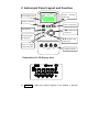
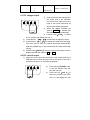
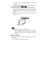
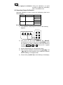
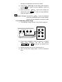
Operation Instruction
for Voltage/mA Source
INDEX
1.
2.
3.
4.
5.
6.
7.
8.
9.
Safety Information………………………………………………...1
Instrument Panel Layout and Function………………………..3
Replacing the Battery………………………………………….... 4
Power-on/off of Calibrator .……………………..………..…….5
Output from Calibrator .……...………………...........................5
Other Features…………………………………………................9
Performance Capabilities……………………………………… 9
Calibration…………………………………………………………11
Points for Attention to Use of Operation Instruction……...14
1. Safety Information
To ensure the safety operation, the following signs are used only as
specified in this operation instruction.
Warning
A warning shows that if the operation does not comply
with the following correct instruction, it is possible to
bring hazards to the user or cause damage to the
calibrator in use. The warning also points out how to
avoid the accidents.
!Caution
A caution shows that if the operation does not comply
with the following correct instruction, it is possible to
cause damage to the calibrator in use. The caution
also points out how to avoid maloperation.
Note
A note serves as sign to remind the user that he must
understand the correct operation of the calibrator and
its characteristics.
To prevent the user and the calibrator from any electric shock and
other hazards, it is necessary to observe the following regulations:
Warning
z Do not operate the calibrator at the working field
where there exists flammable gas or explosive gas or
vapor. It is very dangerous to operate the calibrator in
such a surrounding.
z Never apply more than 30V between any two
terminals, or between any terminal and earth ground.
!Caution
z Disassembly:
No one is allowed to remove the split
case (top & bottom) of the calibrator
except professionals.
z In use:
The calibrator can’t perform both input
z Maintenance:
and output simultaneously. No direct
connection can be made between
both input and output.
Periodically wipe the case with a
damp cloth and detergent; do not
use any corrosive solvents.
Note
z To keep the calibrator in a designed accuracy, it needs
warming up 5 minutes before it is put into use.
z If the calibrator is not in use, it is recommended to
shut down the power supply or keep it in an
off-state .In such a way, the battery can prolong its
life greatly. During the operation of the output current,
do your best to adopt external 24VDC power supply
and use the mode of connecting a transmitter, which
can prolong the battery life greatly.
z If the user requires a higher accuracy of the calibrator,
he should make contact with our manufacturer.
2. Instrument Panel Layout and Function
VOLTAGE/mA
SOURCE
function
select key
V/mA
LCD display area
Power switch key
V
ON/OFF key
mA / % select key
mA%
ON
W X output digit
select key
100%
Zero/FS points
Setting key
25% of single
step setting key
25%
S T output value
setting key
+ mA -
XMT
V
30V
MAX
30V
MAX
30V
MAX
+LOOP
OUTPUT
output terminals
Explanation of LCD Display Area
a)
OUTPUT:
When this symbol appears in the display, it denotes
b)
CAL:
c) O FS:
d)
e)
f)
:
:
V, mA , %:
g) ON, OFF:
the calibrator in an output state.
When this symbol appears in the display, it denotes the
calibrator in a calibration state.
This symbol appears when the calibrator is in a state of
calibration, denoting that the zero point or the full scale
point is now in calibration.
When this symbol appears, it denotes that the battery is
nearly used up and needs replacing now.
When this symbol appears, it denotes that the output
digits need setting.
These symbols denote the individual units of current
output values.
These symbols denote that the output signal is turned
on or off.
3. Replacing the battery
Warning
z The test leads must be removed and the power supply of
the calibrator must be shut down prior to replacing the
battery.
If the symbol
appears in the display, it denotes that the battery
is nearly used up and needs replacing according to the following
steps:
1) Remove the test leads and shut down power supply of the
calibrator.
2) Remove the holster from the calibrator. Open the battery cover
at the back of the calibrator by releasing the lock in the
indicated direction.
3) Replace the used-up battery with a new one. Put the battery
cover back and lock it in the indicated direction.
4) Put the holster back onto the calibrator.
4. Power-On/Off of Calibrator
4.1 Power-key Operation
Press the power key to turn on the power supply of the
calibrator. Then press it again to hold it in one second and the
power will be off. When the power is turned on, the calibrator
starts to make self-diagnosis internally and the full screen is in
display. After this, appropriate operation should be carried out.
Note
z Power-on: To ensure the correct operation of the calibrator
with power on. It is good practice to turn off the
power supply pausing 5 seconds, and then restart
the calibration.
4.2 Automatic power-off
By the shipping time, the calibrator is set in the factory like this:
In case there is no operation of the calibrator within a period of
10 minutes after power-on, it will cut off the power supply
automatically. However, users can decide whether they want to
use the function of the automatic power-off or not. The setting
can also be done by themselves. (See section 6.)
5. Output from calibrator
The appropriate output terminal of the calibrator produces the DC
voltage and current set by the user or simulating a transmitter.
!Caution
z During the operation, do not apply voltage to the output
terminal. If any improper voltage is applied to the output
terminal, it will cause damage to the internal circuit.
Output Operation Procedure
Function
Operation
DCV
1OV
% Operation
Display
0.000 V
Setting
Range
0.0000~11.0000 V
00.000~22.000 mA
DCA
20mA
20mA
00.000 mA
-025.00~112.50 mA %
-025.00 mA %
%
5.1 DC voltage output
1)
Insert one end of the test lead into
the output jack of the calibrator
mA
XMT
V
and connect the other end to the
input of the user’s instrument as
+LOOP
OUTPUT
shown in the following diagram.
2) When the display indicates the
symbol ‘OUTPUT’, it denotes that
M +
the calibrator is in an output state.
3) Press the key〔V/mA〕 to select
the V function and display the unit ‘V’.
4) Press the key 〔W〕/〔X〕to select the set digits for output.
5) Press the key 〔S〕/〔T〕to change the value of the set digits.
The value can do carry or number decrement automatically.
Hold the pressed key in one second and the value will be kept
varying.
6) Press the key〔ON/OFF〕to turn on or turn off the output, and the
display indicates the symbol ‘ON’ or ‘OFF’.
30V
MAX
30V
MAX
30V
MAX
5.2 DC current output
1) Insert one end of the test lead into the +mA- output jack of the
calibrator and connect the other end to the input of the user’s
instrument as shown in the following diagram.
+LOOP
mA
XMT
V
30V
MAX
30V
MAX
30V
MAX
2)
OUTPUT
3)
+
Press the key〔V/mA〕to select the mA function and display the unit ‘mA’.
Press the key〔mA/ %〕to
select the output to be set in
mA or % and display the unit
‘mA%’, in which 0% is 4mA and 100% is 20mA.
4) Press the key 〔W〕/〔X〕to select the set digits for output.
5) Press the key 〔S〕/〔T〕to change the numerical value of the
set digits, which can do carry or number decrement automatically.
Hold the pressed key in one second and the numerical value
will keep varying.
6) Press the key 〔ON/OFF〕 to turn on/off the output followed by
displaying the symbol ‘ON’ or ‘OFF’.
5.3 25% of step current output
1) The electric connection is the same as that of the current
output.
2) Press the key 〔V/mA〕 to select the mA function followed by
displaying the unit ‘mA’ or ‘mA%’.
3) Press the key〔mA 25%〕to display the symbol ‘ ’.
4) Press the key 〔mA/ %〕 to select the output to be set in mA or
% followed by displaying the unit ‘mA’ or ‘mA%’.
5) Press the key 〔S〕
〔T〕
/
to change the output in a value of 25% ,
in which 0% denotes 4mA and 100% denotes 20mA. Now press
the key〔mA 25%〕again to exit the step current output.
6) Press the key〔ON/OFF〕to turn on or off the output followed by
displaying the symbol ‘ON’ or ‘OFF’.
5.4 Current Output Set for Zero Point & Full Scale
1) The electric connection is the same as that of the current
output.
2) Press the key〔V/mA〕 to select the mA function following by
displaying the unit ‘mA’.
3) Press the key 〔mA 100%〕 to display the symbols ‘ ’ and ‘0
FS’.
4) Press the key 〔mA/ %〕 to select the output to be set in a
certain value of mA or mA% followed by displaying the unit ‘mA’
or ‘mA%’.
5) Press the key 〔S〕/〔T〕, which can change the output in a
value of 100% , where 0% denotes 4mA and 100% denotes
20mA. Now press the key〔mA 100%〕again to exit the step
current output.
6) Press the key 〔ON/OFF〕to turn on/off the output followed by
displaying the symbol ‘ON’ or ‘OFF’.
5.5 Simulating Transmitter output (absorption current)
1) Insert one end of the test lead into the XMT output jack of the
calibrator and connect the other end to the input of the user’s
instrument and the power supply as shown in the following
diagram.
2) The key operation is the same as that of DC current output in
subsection 5.2.
+LOOP
mA
XMT
V
30V
MAX
30V
MAX
30V
MAX
OUTPUT
+
+
Note
z Range of power supply: 5 to 25VDC
z During the operation at the current output, try your best to
use an external 24VDC power source in a mode of
connection with a transmitter, thus being able to prolong the
battery life.
6. Other Features
The following operation can change the automatic power-off function
of the calibrator:
1) Turn off the power supply of the calibrator.
2) Press the key〔POWER〕when the full screen appears in the
display. Now release the〔POWER〕key, and immediately press
the key〔mA%〕to enter the calibrator in a maintenance state
when the symbol ‘AP-XX’ appears in the display.
3) Press the key〔T〕when the symbol ‘AP-OF ’appears in the
display, denoting that there is no automatic power-off function
available to the calibrator. When the symbol ‘AP-ON’ appears in
the display, the calibrator recovers its automatic power-off
function.
4) Turn off the power supply again to exit the maintenance state.
7. Performance Capabilities
Output Function & Specification :(applicable to temperature
range from 18℃to 28 ℃ ,within one year after calibration)
Output
DCV
Range
10V
DCA
20mA
Output
Range
0.000
to 11.000V
0.000
to 2.000mA
Resolution
1mV
(absorb.
-20mA
0.000
to-22.000mA
Remark
± 0.05% of
Max. output
set value
current: 2 mA
±2mV
0.001mA
Analog
transmitter.
Accuracy
0.001mA
± 0.05% of
Max. load:
set value ±
1kΩ at 20mA
4μA
note 1
± 0.05% of
Max. load:
set value ±
1kΩ at 20mA
4μA
current)
Loop
power
±10%
24V
Max. output
current:25mA
Notes: 1.When the battery voltage exceeds 6.8V, the maximum load
is 1KΩ at 20mA. When its voltage lies between 5.8V and
6.8V, the maximum load is 700Ω at 20mA.
2.Temperature coefficient: ±0.005% of range per ℃ for the
temperature ranges 5℃ to 18℃ and 28℃ to 50℃.
General Specifications
z
Power supply:
z
Battery life:
z
Max. permitted voltage:
z
z
z
z
z
z
z
Operating temperature:
Operating relative humidity :
Storage temperature:
Storage humidity:
Size:
Weight:
Accessories:
z
Option:
z
Safety:
9V battery (ANSI/NFDA 1604A
or IEC 6LR619V alkaline)
ca.12 hours under the condition
of 10mA
30V(between any two terminals
or between any terminal and
earth ground)
0℃ to 50℃
≤80﹪RH
≤-10℃ to 55℃
≤90﹪RH
200×100×40 mm(with holster)
550g (with holster)
operation instruction, a set of
CF-36 industrial test lead (with
alligator clips attached to probes)
AC power-supply adapter
(VCPS), industrial test lead
(CF-31-A with probe clips)
Certified
as
compliant
to
IEC1010 provisions ( Safety
standard issued by International
Electrotechnical Commission)
8. Calibration
Note
z In order to keep the designed accuracy of the calibrator, it is
recommendable to calibrate your calibrator once a year. The
following example shows the use of recommended standard
equipment to perform the calibration.
!Caution
z During the operation, never apply more than maximum permitted
voltage to the output terminal of the calibrator, otherwise the
overvoltage will lead to possible damage to the output section.
z During the operation, avoid short circuit and never apply more
than the maximum permitted voltage to the output of the calibrator
or to a coworking standard device, otherwise any maloperation
will cause possible damage to their internal circuits.
8.1 Selecting Standard Equipment
Calibrating Output Characteristics
Calib.Item
Standard
Equipment
Input
Range
Accuracy
Recommend.
1281(FLUKE)
DCV
10V
Digital meter
Max.11v
± (10ppm+50μv)
DCA
20mA
Digital meter
Max.22mA
± (50ppm+0.4μA)
or equivalent
8.2 Ambient Condition for Calibration
Ambient temperature:
Relative humidity:
Warming-up:
23℃± 1℃
45 to 75% RH
z Standard equipment must be
warmed up to the given time.
z Do not connect the calibrator to the
power supply until it has been
exposed to the calibrating ambient
condition for 24 hours. Then set the
calibrator to a non-automatic power
off state followed by warming it up to
half an hour.
Note
Power supply for calibration: During the calibration, it is good
practice to replace the old battery
with a new alkaline one.
8.3 Operation Output Calibration
Operating calibration in order of items and calibration points in the
following table:
Item No.
Output Range
Calib.Point
1
DCV/10V
O
FS
O FS
2
DCA/20mA
O
FS
8.3.1 Calibrating 10V range
1) The calibration wiring diagram is shown in the following
diagram:
digital meter1281)
GUARD
+LOOP
mA
XMT
V
30V
MAX
30V
MAX
30V
MAX
OUTPUT
I+
I-
Hi
Lo
2) First press the two keys 〔 V/mA 〕 and 〔 mA/% 〕
simultaneously ,and then press the key〔POWER〕to enter
the calibrator in a state of calibrating 10V output when the
symbols ‘OUTPUT’, ’CAL 0’,’ON’ and the unit ‘V’ appear
in the display.
3) Set the digital meter to a corresponding range.
4) With the output stabilized, operate the keys〔W〕
〔X〕
/
and
〔S〕/〔T〕to set the indication of the calibrator in identity
with the reading of the digital meter.
5) Press the key〔mA 25 %〕to start flashing in the display,
denoting the calibrated point has been stored.
6) Press the key 〔mA/ %〕 and the display will indicate the
symbol ‘CAL FS’. With the output stabilized, repeat the
steps 4 and 5.
7) Now press the key 〔mA/ %〕 again and the display will
indicate the symbol ‘CAL 0 FS’. With the output stabilized,
repeat the steps 4 and 5.
Note
Calibration storage :Press the key〔25%〕 to store the calibrated
point when the display does not start flashing,
denoting that the calibration storage is invalid.
8.3.2 Calibrating 20mA range
1) The calibration wiring is shown in the following diagram:
digital meter(1281 )
GUARD
+LOOP
mA
XMT
V
30V
MAX
30V
MAX
30V
MAX
OUTPUT
I+
I-
Hi
Lo
2) Press the key〔V/mA〕to enter the calibrator in a state of
20mA output calibration, and then the symbols
‘OUTPUT’,’CAL 0’ , ‘ON’ and the unit ’mA’ appear in the
display.
3) Repeat the steps from 3 to 6 in subsection 8.3.1.
4) Turn off the power supply again to exit the calibration
state.
9. Points for Attention to Use of Operation
Instruction
z The present operation instruction is subject to change without
notice.
z The content of the operation instruction is regarded as correct.
Whenever any user finds its mistakes, omission, etc., he or she
is requested to make contact with the manufacturer.
z The present manufacturer is not liable for any accident and
hazard arising from any maloperation.
z The functions described in this operation instruction should not
be used as grounds to apply this product to a particular
purpose.
MB-0004-01