1
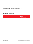
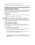
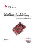
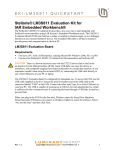
Stellaris® LM3S3748 Evaluation Kit
README FIRST
The Stellaris LM3S3748 Evaluation Kit provides a low-cost way to start designing
applications with Stellaris microcontrollers on a compact and versatile evaluation platform.
The evaluation kit design highlights the LM3S3748 microcontroller’s key features including
USB 2.0 full-speed (12 Mbps) controller, Analog-to-Digital Converter (ADC), and serial
interfaces. The LM3S3748 Evaluation Board (EVB) includes connectors for both embedded
USB Host and USB Device operation.
The LM3S3748 EVB can be used either as an evaluation platform or as a low-cost in-circuit
debug interface (ICDI). In ICDI mode, the on-board microcontroller is bypassed, allowing
programming or debugging of an external target.
Power to the EVB can be supplied through the DC jack, the USB Device connector, or the
USB debug interface connector. A small switch controls whether the board is bus-powered
using the USB Device connector or self-powered using the DC jack or USB debug interface
connector.
WARNING: Do not change the power mode switch while power is applied. Doing so
may damage the switch contacts.
Stellaris One-Day Workshop - LM3S3748 README FIRST
5-1
Procedure
Hardware list:
¾ PC with two USB ports, running Microsoft® Windows 2000, XP, or Vista
¾ USB cable
¾ LM3S3748 evaluation kit
Software list:
¾ Workshop Installation Flash Drive
5-2
Stellaris One-Day Workshop - LM3S3748 README FIRST
Procedure
Procedure
Initial Board Set-Up
1. Power the EVB
Move the USB power mode switch (SW3) to the SELF position as shown below.
Note: The switch must be placed in the SELF position for the initial board setup to work
correctly.
2. Connect the USB cable to the board
Using one of the USB cables provided in the kit, connect the mini-b (smaller) end of the USB
cable to the USB debug interface connector labeled DEBUG USB on the EVB.
Note: If the USB cable is not plugged into the DEBUG USB connector, the board will not be
powered and you will not be able to install the FTDI drivers in the next section.
3. Connect the USB cable to your PC
Connect the other end (Type A) of the USB cable to a free USB port on your host PC.
The PC’s USB port is capable of sourcing up to 500 mA for each attached device, which is
sufficient for the evaluation board. If connecting the board through a USB hub, it must be a
powered hub.
You should see Windows recognize the three devices in the board’s composite USB device.
Stellaris One-Day Workshop - LM3S3748 README FIRST
5-3
Procedure
Quickstart Application
The LM3S3748 Evaluation Board comes preprogrammed with a quickstart application.
Once you have powered the board, this application runs automatically. You have probably already noticed this running as you installed the drivers. A splash screen appears on
the LCD for a few seconds before the application begins.
The quickstart application provides a simple two channel oscilloscope sampling at up to
1M samples per second. The two oscilloscope channels are differential measurement
channels which provide waveform acquisition using the LM3S3748 microcontroller’s
Analog-to-Digital Converter (ADC). The evaluation board includes an oscilloscope
header that contains the two channel differential inputs, two test point pins, and two test
ground pins.
Test Point 1 is connected to the speaker input on the EVB and allows the signal for the
keyboard click to be viewed. Note that waveform capture is typically not taking place
while the keyboard is being serviced so the click may not be seen on the waveform display for every keypress.
Test Point 2 is connected to the output of a PWM generator set to drive a 1KHz square
wave.
5-4
Stellaris One-Day Workshop - LM3S3748 README FIRST
Procedure
The EVB has a four-way navigation switch with press-to-select functionality that is used
to configure the oscilloscope. The navigation switch is labeled NAVIGATE on the
board. Rocking the control in the desired direction sends up, down, left, or right messages to the application and pressing on the center sends the select message.
Controls and settings are arranged into groups by function such as display settings, trigger settings, file operations, and setup choices. These groups are accessed by pressing
select to display the main menu. With the menu displayed, use up and down to navigate
between the available groups. When the desired group is highlighted, press select once
again to dismiss the menu.
Controls from the currently selected group are shown in the bottom portion of the LCD.
Use up and down to cycle through the controls in the group and left and right to change
the value of, or select the action associated with, the control which is currently displayed.
Using the oscilloscope to view Test Point 1 and Test Point 2, make the following connections using the included jumpers:
1. Connect Test Point 1 to Channel 1+.
2. Connect Test Ground to Channel 1-.
3. Connect Test Point 2 to Channel 2+.
4. Connect Test Ground to Channel 2-.
The connections should look like the graphic below.
Stellaris One-Day Workshop - LM3S3748 README FIRST
5-5
Procedure
5. The test point signals should now be visible on the LCD. To modify the volts per division and time per division options, follow these additional steps. Press select to bring
up the main menu, navigate to highlight the Display group, and press select again. The
Display group will be displayed at the bottom of the LCD.
Note: The Display group is the default active group after power-up.
6. Press up or down until the Timebase option is selected and then press left or right to
modify the amount of time per division.
7. Press up or down until the Ch1 Scale or Ch2 Scale option is selected and then press
left or right to modify the number of volts per division for that channel.
5-6
Stellaris One-Day Workshop - LM3S3748 README FIRST
Procedure
USB Device Mode
The quickstart oscilloscope application can connect to a Windows host machine via USB
where a companion application running on the PC can be used to control the oscilloscope
and display and save the waveforms. In this mode, the LM3S3748 EVB will be operating
in USB device mode.
The first step is to install the necessary USB drivers on the PC.
1. Disconnect the USB cable from the USB connector labeled DEBUG USB if connected.
2. Move the USB power mode switch (SW3) to the BUS position.
3. Connect the mini-b (smaller) end of the USB cable to the USB device connector labeled USB DEVICE on the EVB. Connect the other end (Type A) to a free USB port on
your host PC.
4. Windows starts the Found New Hardware Wizard and asks if it can connect to
Windows Update to search for software. Select No, not this time and then click Next.
Stellaris One-Day Workshop - LM3S3748 README FIRST
5-7
Procedure
5. Next, the Found New Hardware Wizard asks you from where to find the installation software. Select Install from a list or specific location (Advanced) and click Next.
6. Make sure that the Workshop Installation Flash Drive is installed and ready in one
of your laptops USB ports. Select Search for the best driver in these locations, and
check Include this location in the search. Browse on the Flash Drive to the folder
named F:\windows_drivers (the drive letter may be different) and click Next
7. When the driver installation is finished, click Finish to close the dialog box.
5-8
Stellaris One-Day Workshop - LM3S3748 README FIRST
Procedure
8. The next step is to install the Windows Oscilloscope application from the Workshop
Installation Flash Drive.
Note: The Windows oscilloscope application only supports WindowsXP and Vista.
Make sure that the Workshop Installation Flash Drive is installed and ready in one of
your laptops USB ports.
9. Using Windows Explorer, open the Workshop Installation Flash Drive, find the
file named SW-USB-win-xxxx.msi and double-click on it.
When the Setup Wizard appears, click Next and Next again to select the default installation folder. Agree to the license and click Next. Finally click Next to start the installation.
When the installation completes, click Close.
10. After the USB examples have been installed, you can run the Oscilloscope application by clicking Start Æ All Programs Æ Texas Instruments Æ Stellaris Æ USB Example Æ
LM Oscilloscope.
You should be able to see and control the application on the board using the Windows
application. If you do not see the waveform in the display, disconnect and reconnect the
USB cable on the evaluation board.
Close the Windows application when you are finished.
Stellaris One-Day Workshop - LM3S3748 README FIRST
5-9
Procedure
USB Host Mode
The quickstart oscilloscope application can also run in a USB Host mode. To run the application in USB Host mode, do the following:
1. Disconnect the USB cable from the evaluation board.
2. Move the USB power mode switch (SW3) to the SELF position.
3. Connect the mini-b (smaller) end of the USB cable to the USB debug interface connector
labeled DEBUG USB on the EVB. Connect the other end (Type A) to a free USB port on
your host PC.
4. Press select to bring up the main menu, navigate to highlight the Setup group, and press
select again. The Setup group will be displayed at the bottom of the LCD.
Press up or down until the USB Mode option is selected and then press left or right to
switch to Host mode.
Note: We have had some issues with a recent revision of the quickstart application when
switching to host mode. If the application appears to freeze at this point, you will need to reflash the application. The flash programmer lab in chapter 6 will step you through this process.
In USB Host mode, the quickstart application can save waveforms to a USB flash memory
stick or a Micro-SD card. The waveform files can be saved in bitmap (.bmp) or as comma
separated value (.csv) formats. The LM3S3748 Evaluation Kit includes a USB flash memory
stick, but a Micro-SD card is not included.
To save waveforms to the USB flash memory stick, do the following:
5. Plug the USB memory stick into the USB HOST connector. You should see a USB drive
detected message on the LCD.
6. Press select to bring up the main menu, navigate to highlight the File group, and press
select again. The File group will be displayed at the bottom of the LCD.
7. Press up or down until the BMP on USB option is selected, and then press left or right
to save the bitmap waveform file to the USB memory stick.
8. Press up or down until the CSV on USB option is selected, and then press left or right to
save the comma separated value waveform file to the USB memory stick.
5 - 10
Stellaris One-Day Workshop - LM3S3748 README FIRST
Procedure
Where to Find More Information
For more information on the LM3S3748 Evaluation Kit, see the Stellaris LM3S3748 Evaluation Kit User’s Manual.
For more information on the LM3S3748 Evaluation Kit Quickstart Oscilloscope Application,
see the StellarisWare® Driver Library User’s Guide in the LM3S3748 Evaluation Kit’s Example Applications section.
The above mentioned documents can be found on the Stellaris LM3S3748 Evaluation Kit CD
or at the www.ti.com/Stellaris web site.
Software Development Tools
The next step is to install and run the software development tools included in the evaluation
kit. For more information, see the quickstart guides included on the Stellaris LM3S3748
Evaluation Kit CD. Additional tools may be available through the www.ti.com/Stellaris web
site.
References
The following references are included on the Stellaris LM3S3748 Evaluation Kit Documentation and Software CD and are also available for download at www.ti.com/Stellaris:
•
Stellaris LM3S3748 Evaluation Kit User's Manual
•
StellarisWare Driver Library
•
StellarisWare Driver Library User’s Guide
•
Stellaris LM3S3748 Microcontroller Data Sheet
You’re done.
Stellaris One-Day Workshop - LM3S3748 README FIRST
5 - 11
Procedure
*** one more blank page ***
5 - 12
Stellaris One-Day Workshop - LM3S3748 README FIRST