1
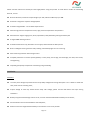
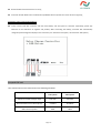
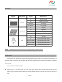
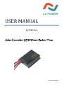
USER MANUAL LCCD-A1 Solar Controller+LED Driver+Built-in Timer 20120314 VERSION 1 Please read the instructions carefully and thoroughly before using the product. It comes with a number of outstanding features, such as: Build-in LED driver, maximum output voltage up to 70V, maximum efficiency up to 96%. Automatic recognition of system voltage 12/24 V Protection degree:IP68 -- in1.5m water depth 72hours External high precision temperature sensor, high precision temperature compensation. Advanced four stage charging (main, boost, equalization, float) effectively prolong the battery life. 4 stages PWM dimming function. Professional LED driver chip, with little current ripple, which extends the LED span life. Built-in intelligent learning function easily realizing automatically lights on in the morning. With electricity protection data-saving function. Complete protections on reverse polarity (battery or solar panel), over-charge, over-discharge, over load, short circuit, TVS lightening; Imported good-quality components contributing to high reliability; Installation Attentions The solar panel voltage may exceed human body safety voltage when wiring 24V system. So it is better to shade the solar panel and use insulating tools; Output voltage of load may exceed human body safe voltage; please connect LED before load open during installation. Battery may permanent damage if short circuit, one fuse recommended between battery and controller; Good ventilation area recommended for heat dissipation; Make sure the wire length between battery and controller is as short as possible Page 2/8 Recommended minimum wire size: 2.5mm²; Controller be with Reverse Current Protection by MOSFET which inspects the current direction regularly; Installation steps & connection diagram Firstly connect load with controller and then wire battery and solar panel to controller respectively; please pay attention to the distinction of negative and positive; After connecting the battery, controller will automatically recognize system voltage and display on the nixie tube. (“12” stands for 12V system, “24” stands for 24V system.) Accepted LED load User should make sure the LED load can meet following standards 12V system 24V system LED driver output voltage range 16V~70V 32V~70V Recommended series LED lamp qty. 5~20PCS 10~20PCS LED load max. power 30W 60W Page 3/8 LED display Symbol Equipment Status Description on battery working off no battery connected slow flash low voltage quick flash over voltage on daytime off nighttime slow flash charging quick flash over tempreture, stop charging off load off on load work with 100% power flash for 3 times load work with 75% power flash for 2 times load work with 50% power flash 1 time load work with 25% power battery solar panel load Remark: Slow flash frequency is about 2 times/s, quick flash frequency is about 2 times/s. Output mode The controller can automatically detect day/night through testing the open circuit voltage of the solar panel, no setting of a clock is required. It gets the dawn light start time through learning to daytime and nighttime in different area or season. There are 4 output modes available: Light control “on” and time control “off” (1-4.): Load starts working when controller detects night and stop working as set time (the load stops working if controller detects “daytime” no matter the set time is achieved or not); Page 4/8 Morning Mode (4~5): The load would be turned on automatically in the morning, the output power is adjustable. Manual mode (6): can switch output performance manually no matter daytime or night; the power is adjustable. Debug mode ( ): used for debugging and installation; Remark: if the battery is over charge or discharge, the controller will cut off the load not matter under which mode. Imag e on tens dig it Model Imag e on un it dig it P arameter L oad work with 100% power ~ W ork period (0~14hours) L oad work with 75% power ~ W ork period (0~14hours) L oad work with 50% power ~ W ork period (0~14hours) T he fourth period of time ~ W ork period (0~14hours) 1 dawn light power 25% Morning mode ~ 2 dawn light power 50% 3 dawn light power 75% 4 dawn light power 100% 0 load off 1 load work with 25% power Manual mode ~ 2 load work with 50% power 3 load work with 75% power 4 load work with 100% power D emo model Remark: the dot behind units digit on nixie tube stands for 10; (eg. 3. Stands for 13) Page 5/8 Keys and settings Skip Press: press the button within 2 seconds Confirm Press: press the button within 2 to 4 seconds. Configure Press: press the button over 4 seconds Browse Mode: nixie tube tens digit is “on” (except ). Setting mode: nixie tube unit digit is twinkling. Configure mode: nixie tube tens digit is showing symbol “ ” 1. Under browse mode, user can “Skip Press” to view status of each output mode. When it goes to the expected output mode(1-5), “Confirm Press” to enter setting mode, nixie tube unit digit would flash; “skip press” to chose the expected output mode parameter; “confirm press” to confirm and exit the setting mode. 2. Under browse mode and nixie tube tens digit showing “6”, “confirm press” to enter manual output mode, nixie tube unit digit would flash, “skip press” to chose the expected output power. When you want to exit the manual mode, “confirm press” to enter browse mode. 3. Under browse mode and nixie tube tens digit showing (1-5), “configure press” to enter configure mode,. When you want to exit the configure mode, “configure press” or wait for 3 minutes to enter browse mode. Page 6/8 Technical data System voltage 12/24 V auto recognition Max. charge/load current 10A Output current 300mA~3300mA Float Charge 13.8V/27.6V(25℃) Main Charge 14.4/28.8 V (25 °C), 30 min. (daily) Boost charge 14.4/28.8 V (25℃), 2 hAc va on: ba ery voltage < 12V/24V Equlization charge 14.8/29.6V Deep discharge protec on:Cut-off voltage 11V/22V Deep discharge protec on:Reconnect voltage 12V/24V Overvoltage protection 16V/32V Max. panel voltage 55V Temperature compensation -4mV/℃·2V Self consumption 5 ~ 10mA Day/night detect voltage Day:>9V; night: <7V Day/night detect delay 3min Working temperature -40~+50℃ Maximum above sea level 4000m Size 82x59x20mm Weight 160g Protection degree IP68(1.5m, 72h) Remark: 1. The two voltage levels before/after the slash are valid for 12V and 24V systems respectively. 2. only solar panel or load can full load running if environment temperature is over 55℃ Page 7/8 Common problems & Solutions Phenomenon Problem Battery indicator off Battery working problem Battery indicator slowly flash, without output Battery indicator quick flash, without output Solution Make sure the wiring between controller and battery is correct. Battery under over discharge protection Charge to recover voltage Battery under overvoltage protection Cut off output for protecting load, auto working after recovering voltage Solar panel wiring problem Make sure the wiring between controller and solar panel is correct. Solar indicator “on” in nighttime, without load output System cannot detect night System detects “night” when solar voltage drops less than 7V; Solar indicator be “off” and with load output; make sure solar panel not shone by light if no output 3 min. later. Solar indicator quick flash No charging Others - Solar indicator “off” in daytime Over temperature, solar charging “off” system auto recovered when temperature return to normality. Check the wiring SUBJECT TO CHANGE WITHOUT NOTICE VERSION 20130301 MADE IN CHINA SHENZHEN LICHUANG POWER CO., LTD Page 8/8