1
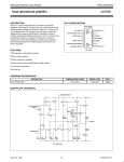
PAMP 4
Grundig SAT Systems
PROFESSIONAL
PROFESSIONAL
AMPLIFIER
CONTENTS ________________________________________________________
3
General
Scope of delivery
Technical data
4
Functional Description
The GaAs hybrid amplifier PAMP 4
5
Installation, Connecting
Installing the hybrid amplifier into a professional satellite unit and
connecting it
Lowering the output level
6
Preparations
Expert installation of the IEC coaxial right-angle plug and
the coaxial cable
7
Setup
Setting up the hybrid amplifier
Service (at the end of this user manual)
2
Subject to technical modifications and errors!
GENERAL ___________________________________________________________
Scope of delivery
1 hybrid amplifier PAMP 4
1 screened lead for the voltage supply
5 IEC coaxial right -angle plugs with covers
1 user manual
Technical data
This product conforms with the requirements of
the 73/23/EC and 89/336/EC guidelines of the
European Council.
The standards EN 50083-2, EN 50083-2/A1,
EN 50083-1 and EN 60065 required for the
CE certification are kept to.
RF input
Input frequency range:
Input impedance:
Input level:
Input level control range:
Amplification:
Noise factor:
47 MHz ... 862 MHz
75 Ω
max. 86 dBµV
0 to – 20 dB
typ. 37 dB
about 7 dB
RF output
Output frequency range:
Output impedance:
Measurement output:
47 MHz ... 862 MHz
75 Ω
– 30dB
Max. output level at 862 MHz
60 dB – IMA 3rd order1):
60 dB – CTBA (CENELEC) 2):
60 dB – CSOA (CENELEC) 3):
Output level control range:
Equalization:
Push-pull amplifier, can be deactivated:
123 dBµV (– 8 dBµV)
110 dBµV (– 8 dBµV)
113 dBµV (– 8 dBµV)
0 to – 20 dB
0 to – 20 dB
115 dBµV
Power supply:
Power consumption:
Ambient temperature:
––, +
––
+ 24 V --– 4 V --about 15 Watt
–10°C to +50°C
4 IEC sockets, female
1 IEC socket, female
1 IEC socket, female
1) according to EN 50083 Part 5, (DIN 45004 B)
2) according to EN 50083 Part 3, CTBA at 60 dB – IMA, CENELEC norm
norm with 42 channels
3) according to EN 50083 Part 3, CSOA at 60 dB – IMA, CENELEC norm
with 42 channels
ENGLISH
Connectors and controls
RF inputs 1, 2, 3, 4:
– 1 level control per input
RF measurement output:
RF output:
– with output level control
– with EQUALIZATION control
3
FUNCTIONAL DESCRIPTION __________________
LEVEL CONTROL
RF-OUTPUT
MEASURING
INPUTS ––––– 1 ––––– 2 ––––– 3 ––––– 4
OUTPUT
EQUALIZATION INPUT LEVEL CONTROLS ––– 1 ––– 2 ––– 3 ––– 4
CONTROL
The GaAs hybrid amplifier PAMP 4
This hybrid amplifier has been designed according to the
latest GaAs technology.
It comprises 4 Interstage RF inputs, 1 measuring RF output
(–30 dB), and 1 RF output.
The level of each of the 4 inputs can be adjusted with the
associated level control.
Due to the different cable loss over the frequency range of
the cable system, the equalization can be adjusted with the
associated control.
The output level at the RF output of the hybrid amplifer can be
reduced by about –20 dB with the associated control.
The block diagram of the hybrid amplifier
Level controls
Inputs 1... 4
Input 1
Input 2
––
+ 24 V --Diagonal adjuster
(Equaliser)
– 8 dB
S1
Level control
Output
S2
Output
Input 3
Input 4
––
+ 12 V --S3
4
Measuring
output
(–30 dB)
PREPARATIONS _____________________________________________
Expert installation of the IEC coaxial
right-angle plug and the coaxial cable
Note :
For the installation, only coaxial cables with a minimum
diameter of 6.8 mm and a maximum diameter of 7.2 mm
must be used.
1
9
9
1 Remove the outer insulation, the screening, and the inner
conductor of the coaxial cable accurately to the size, and
then fit the screening of the coaxial cable over the outer
insulation (see Fig. 1).
6
2
2 Slide the coaxial cable into the right-angle plug, press the
inner conductor of the coaxial cable into the contact slot of
the right-angle plug, and finally use an appropriate soldering iron to solder together the parts (see Fig. 2).
3
3 Use appropriate crimp pliers to firmly press together the
metal shoe (arrow) of the right-angle plug (see Fig. 3).
Press the enclosed cover into the opening of the right-angle
plug.
Alfred Knitter GmbH
Colditzstraße 28
D -12099 Berlin-Tempelhof
Tel.: 030/75 68 06-0 • Fax: 030/75 68 06-44
E-Mail: [email protected]
ENGLISH
Recommendation:
Appropriate crimp pliers with the required inserts can be
purchased from:
5
PREPARATION ________________________________________________
Lowering the output level
If you need a lower output level, but want to retain the noisevoltage ratio, you can change the jumpers as shown below.
1 Use a Torx screwdriver (TX6) to remove the 10 screws and
take off the top of the housing.
2 Plug in the jumpers as shown below.
– Signal path a – the push-pull amplifier is switched off
(factory setting).
S 1
a
b
S 3
b
S 2
a
b
a
a
b
3 Attach the upper housing again and screw it on.
6
INSTALLATION, CONNECTING _____________
Installing the hybrid amplifier into a professional satellite unit and connecting it
Important!
Due to its rather high power, it is not allowed to
use the hybrid amplifier inside the professional
satellite unit STC 332.
Attention!
Before installing or replacing the hybrid amplifier, satellite boxes, or the power supply and
control unit, it is absolutely necessary to disconnect the power supply plug of the professional satellite unit (headend) from the wall outlet.
1 Connect the IEC plug of the enclosed screened lead with the
HF socket (+24 V ) on the back of the hybrid amplifier, and
–– « contact on
the other end of the lead with the » +24 V --the backplane of the professional satellite unit (see Figure).
L100
L101
L103
C100
LNCBREITBA
+18V
+24
ROT
GRUEN
+18V
Anschl.
2 Installl the hybrid amplifier into the plug-in location next to
the power supply and control unit of the professional
satellite unit, and then fix it with the screws to the mounting
frame.
OUTPUT
INPUT
3 Connect the RF output sockets (output collector) of the
professional satellite unit with the RF input sockets of the
hybrid amplifier using RF cables.
Note:
Terminate not used inputs of the hybrid amplifier with 75 Ω
resistors.
4 Connect the power supply plug of the professional satellite
unit with a wall outlet (220-240 V~, 50/60 Hz).
Important!
The professional satellite unit is only completely separated from the mains voltage by pulling the power supply plug.
ENGLISH
Supply voltage of the hybrid amplifier
–– via the screened lead)
(+24 V ---
7
SETUP __________________________________________________________________
LEVEL CONTROL
RF-OUTPUT
MEASURING
INPUTS ––––– 1 ––––– 2 ––––– 3 ––––– 4
OUTPUT
EQUALIZATION INPUT LEVEL CONTROLS ––– 1 ––– 2 ––– 3 ––– 4
CONTROL
Setting up the hybrid amplifier
Important!
Precondition for the setup of the hybrid amplifier is a
correct installation, connection, setup and level adjustment
of the satellite boxes fitted in the professional satellite unit.
1 Turn all 6 level controls of the hybrid amplifier clockwise to
their right end stop (= maximum level).
2 Connect a measuring receiver to the RF output of the hybrid
amplifier.
3 Measure the RF output level of the hybrid amplifier, and
then adjust the required output level using the output
level control.
4 Measure the output level (amplification) of every connected
RF input, and then adjust the same level using the associated
input level controls.
Please observe the following in doing this:
The nominal value is the output level of the analog TV
channels.
– Adjust the output levels of digital TV channels (64 QAM)
about 6 to 10 dB lower.
– Adjust the output levels of FM radio programmes about
10 dB lower.
5 Adjust the RF output level of the hybrid amplifier using the
output level control.
6 Only if applicable:
It is possible to adjust the equlization of the cable
system’s cable loss using the »EQUALIZATION« control.
8
GSS Grundig SAT Systems GmbH • Beuthener Str. 43 • D-90471 Nürnberg • http://www.gss.tv