1
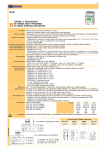
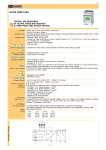
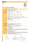
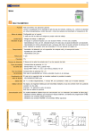
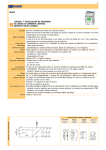
1/5 SVP CONTROL AND VISUALIZATION OF VOLTAGE, PHASE AND FREQUENCY IN THREE-PHASE LINES WITH NEUTRAL Function Operating mode Voltage control Phase sequence control Control unbalance Ln-Ln Control unbalance Ln-N Frequency control Timing Voltage precision Frequency precision Display of the reading value Output relay Output 4-20 mA PC communication Supply voltage Warning Voltage relay for three-phase lines with neutral. Control of an auxiliary voltage or of its own supply voltage. Configurable by the user. Each one of the available relays it is assigned with its own operating mode for one or more magnitudes, reacting by the first one which is produced. · Operating margin: ±18% of the nominal voltage. · Operativity by maximum and/or minimum voltage between phases.Independent adjustment L1-L2, L1-L3, L2-L3, L1-N, L2-N and L3-N. At each case, adjustment for detection and/or for release. · Reading value RMS It is detected only at the start-up of the relay or when three-phase line is applied. Adjustable from 0 and 100%. · Only one adjustment for the three phases. Adjustable from 0 and 100%. · Only one adjustment for the three phases. · Adjustable from 43..70 Hz. · Operativity by maximum and/or minimum frequency. At each case, adjustment for detection and/or for release. · If the frequency changes in such a value that the relay loose the required precision for a normal operating mode, it switches to the alarm mode (See page 4 for detailed information). · Associable to the detection and/or to the release of whichever relay. · Adjustable from 0,01s..999,9h · Repeating precision ±30 ppm Taken over the read value: · For L1-L3 and L2-L3: 0,8% (50Hz) / 1,0% (60Hz) · For L1-L2: 0,9% (50Hz) / 1,1% (60Hz) · For L1-N and L2-N: 1,3% (50Hz) / 1,1% (60Hz) · For L3-N: 0,7% (50Hz) / 0,6% (60Hz) Taken over the read value: 0,3% The value of the read magnitudes is displayed by means of the following status screen: · VOLTAGE L1-L3: Voltage between L1 and L3 · VOLTAGE L2-L3: Voltage between L2 and L3 · VOLTAGE L1-L2: Voltage between L1 and L2 · VOLTAGE L1-N: Voltage between L1 and neutral · VOLTAGE L2-N: Voltage between L2 and neutral · VOLTAGE L1-N: Voltage between L3 and neutral · FREQUENCY: Frecuencia de la red · |Li-Lj|: Unbalance between phases · |Li-LN|: Unbalance between phases · PHASE CYCLE: Phases sequence From 1..3 independent relays, SPST NO. By default, we supply three relays. It is assigned to whichever of the measured magnitudes (voltage L1-L2, voltage L2-L3, voltage L1-L3, voltage L1N, voltage L2-N, voltage L3-N, frequency, unbalance phase-phase, unbalance phase-neutral) to be transmitted through a 4-20 mA current loop, being able to coexist with the relays. Precision: 1% additional to the read value. This kind of output is optional. It is possible to establish different types of communication with a computer (see also last page): - By telephone connector that incorporates standard device and programming interface CPBZ. - By a RS232 connection (optional). - By a connection RS2485 and SBAZ converter (optional). -18% Nominal +18% [024] 24 VAC 50/60Hz Ranges 90,20 110..125 147,50 [110] 110..125 VAC 50/60Hz 180,40 220..240 283,20 [230] 220..240 VAC 50/60Hz 311,60 380..415 489,70 [400] 380..415 VAC 50/60Hz 360,80 440 519,20 [440] 440 VAC 50/60Hz 410 500 590 566 690 814 Three-phase voltage must be disconnected before or simultaneously than the supply voltage, never later. Communication (According options) With auxiliary supply voltage Standard Connection diagram Code 0 With the own supply voltage Voltage in A1-A2 can be connected any three phases, but don’t to neutral. RS232 Code 3 RS485 Code 8 4-20 mA Code 4 2/5 Phases sequence Control for voltage between phases Control for voltage between phase and neutral Frequency Unbalance between phase and between phase and neutral td = Delay on detection / tr = Delay on release State of the relay may vary according to the application. W hat is shown in the diagrams belongs to the set-up of the default user’s programms 1 and 2. 3/5 SVP 18 28 1 15 SVP L 38 2 25 3 35 Voltage phase-neutral Overvoltage category Shock voltage Pollution degree Protection Approx. weight Store temperature Operating temperature Humidity Housing Leds window Buttons, connector, clamp Connector’s terminals Screws torque Norms 300 V III 4 kV 2 (EN61010) IP 20 280 g -30..+80ºC -20..+50ºC < 95% HR Cycoloy - Light grey Lexan - Transparente Technyl - Dark blue Brass 0,8 Nm Dessigned and manufactured under EEC normative. Electromagnetic compatibility, directives 89/366/EEC and 92/31/EEC. Electric safety, directive 73/23/EEC. Plastics: UL 91 V0 Control - Interface Order code Supply voltage 6 A / 240 V 6 A / 24 V 3 A / 240 V 3 A / 24 V > 106 oper. 18.000 operations / hour 360 operations / hour AgSnO Alloy 240 VCA (85 ºC) 1000 VAC 4000 VAC > 100 M(500 VDC) 1 red led per relay 9- SVP With display. Default languages: · Spanish · English · French · Catalan (Other on request) Number of relays 0 - No relays 3 - 3 relays Indication Without display. Communication RS232 / RS485. Type of relay Options selection Screens selection Change of values Text edition Validation Signaling of the supply voltage and status of the relays Communication 0 - No relays A - SPST NO Supply voltage input LCD screen 0 4 3 8 - No bus 4-20 mA RS232 RS485 Contacts of the relays Version (By default, 3) (By default, A) (By default, 0) [024] [110] [230] [400] [440] 24 VAC 110..125 VAC 220..240 VAC 380..415 VAC 440 VAC 00..99 SVP [S···] (By default, 00) Connector communication (under) Supply [903] 15..70 VAC/DC [904] 60..240 VAC/DC To compose the reference, select one option of each column. Example: SVP9 3A400 230 690 Dimensions [904] [024]..[400] [903] 4000 V 2500 V 50 Hz 60 Hz ±18% 15..70 V 60..240 V 2,5 VA 3,5 W 3,1 W 120 ms 110 ms < 600 ms* < 200 ms* 70 ms 60 ms 160 ms 150 ms 1 net cycle and/or >70 ms * and/or -30% of the -30% of the nominal voltage nominal voltage Green led * In the worth of the cases Q - Without display. Without communic. U- Galvanic isolation Frequency Operating margins Consumption Start-up time Detection time Reset Device parts Constructive and enviromental data Output relays N AC Resistive load DC AC Inductive DC load Mechanical life Max. mech. operations Electric life at full load Contact material Operating voltage Voltage between contacts Voltage coil/contact Isolation resistance Indication Ranges [110] [230] [400] [440] [500] [690] 110..125 VAC + N 220..240 VAC + N 380..415 VAC + N 440 VAC + N 500 VAC + N 690 VAC + N 4/5 GENERAL CHARACTERISTICS OF THE DIGITAL CONTROL RELAYS User’s manual How to programm Types of screens Interactive menus Changing values User’s programms Display lighting Value added For a wide knowledgment of the options offered by the digital control relays, the own User’s Manual for each model must be read. Although an issue is given with every purchased device, a copy can be donwloaded in our web site (www.disibeint.com). The digital control relays can be indistinctly programmed either with the buttons placed in the front of the housing or with a personal computer. Please refer at the end of this page to learn more about the PC programming alternative. Status: They show the actual values of the magnitudes controlled by the relay. User: Where the user can write a customized text to help to the relay identification. Options: For accessing to the menus for the options selection. Informatives for values: They show the information of the different set parameters. Change of value: For modifying the values of the different values. Screens menus: Group of screens related under the same concept and that can contain whichever type of the screens previously described. For an ease programming, into the menus only the options that can be set are the ones visible. The rest of the options are not visible. This feature is interactive, ie., it is produced automatically according whether other functions are activated or not. The screens for changing the values contain the margins betwen such value can be adjusted. These margins can depend of other options and this is because different margins could be displayed according to other previous relations. Provided by factory two programs with options and pre-configured settings for quick start-up team. In most cases, these parameters should be tweaked to suit the characteristics of each installation. The user can create your own program and store it on your computer. The display remains backlihghted while it is accessed to the different screens. If any button is not pressed for longer than 30 seconds, the light turns off. In order to turn the light on, it is enough to press any button only once. - Four languages available in each relay - Graphic bar for the intuitive visualization of the displayed value - Historical control of the maximum values obtained by the relay - Screen’s refresh selectable between 1 and 8 times per second - Possibility of locking the keyboard to avoid any undesired modification - Complementary timing functions SPECIFIC CHARACTERISTICS FOR THE MODEL SVP Alarm by frequency deviation This option affects to those relays with any voltage parameter activated. By default, this option is activated. Inhibits the activation of the relay in the state of alarm when the requency is deviated in ± 0,4 Hz during the detection process, and of ± 0,3 Hz during the releas process. For this kind of deviation in the frequency, the operating precision is reduced. More the frequency in the net is deviated, worse precision when reading its voltage. If this option is deactivated, you must remember that the reading precision of the voltage parameters decrease when the frequency gets deviations from its nominal values (50 Hz / 60 Hz). You must consider this reduction of precision when setting the values for detection and/or release. PC COMMUNICATION deCom · Communication and programming software for the digital control relays. · It allows the interactivity between the different types of communication: through the CBPZ interface, RS232 or RS485. · It displays the complete data related to the relay, gruoped by concepts and easing the intuitive programming. · It has control tools to do not exceed the operating margins of each model according to its range. · It is provided with templates to facilitate the programming of each model. · It allows to store the own settings. Windows XP operative system (.NET Framework required). CURRENT LOOP 4-20 mA 5/5 Supply voltage 12..30 VDC 1 88.88 2 mA SBAZ CBPZ ACCESSORIES Interface for remote programming from a PC. It allows the connection between whichever digital relay not provided with bus and a PC. Not required for devices provided with bus RS232, RS485 or with 4-20mA output. RS485 to RS232 signal converter for the remote programming or f or the data capture and visualization from a PC. It allows the connection of up to 31 digital control relays provided with RS485 communication bus, to get an unique codified RS232 output. 2 RxD RxD 2 3 TxD TxD 3 5 GND GND 5 STANDARD MODE *RS-232 wire CBPZ *Serial adapter/USB RxD 2 RS232 COMMUNICATION R xD TxD TxD 3 GND GND 5 * 2 RxD RS485 COMMUNICATION REMOTE PROGRAMMING FROM PC OUTPUTS COMMUNICATIONS CBPZ RxD 2 3 TxD TxD 3 5 GND GND 5 *RS-232 wire #1 #2 # 31 SBAZ *Serial adapter/USB 5 3 2 not supply cables or connectors. * Disibeint You can find these products in stores GND 2 R xD TxD 3 5 TxD R xD GND specializing in computer equipment. Rev. 02/00 · 26/02/14 · DISIBEINT reserves the right to modify this document without previous notice Segle XX, 91 E08032-Barcelona T: +34 934 330 370 F: +34 934 354 532 www.disibeint.com [email protected]