1
Detailed Product Information
Logic Analyzers
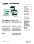
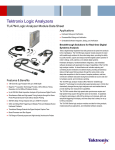
TLA600 and TLA700 Series Logic Analyzers.
TLA Family
The TLA Family of logic analyzers consists of the TLA600 Series and the
TLA700 Series. The TLA600 Series offers a selection of stand-alone logic
analyzer instruments at prices that make 500 ps timing resolution
available to designers of today’s mainstream embedded systems. The
TLA700 Series offers the highest performance for today’s demanding
applications and consists of portable and benchtop modular mainframes
with expansion mainframe capability. Instrument modules include logic
analyzer, pattern generator and digital oscilloscope. A full line of
complementary support products for popular processors and buses is
available for the entire TLA family.
8 GHz MagniVu™ Acquisition Technology Provides up to 125 ps Timing
Resolution on All Channels All the Time Through the Same Probe
Up to 800 MHz State Acquisition with 1.25 Gb/s Data Rate for Advanced
Processors and Buses
Simultaneous State, High-speed Timing and Analog Measurement Analysis
Through the Same Probe Pinpoints Elusive Faults
34/68/102/136-Channel Logic Analyzers with up to 256 Mb Depth with
Hardware-accelerated Waveform Display and Search Functions to Rapidly
Analyze Acquired Data
4-Channel Digital Oscilloscope with up to 1 GHz, 5 GS/s Provides High-fidelity
Signal Quality Measurements of Digital Signals
64-Channel Pattern Generator with up to 268 MHz and up to 2 Mb Depth
Provides Stimulus for Functional Verification, Debugging and Stress Testing
Integrated View (iView™) Capability Provides up to 6 GHz, 20 GS/s, and 32 Mb
with a Stand-alone Tektronix TDS Digital Storage Oscilloscope
TLAVu™ and PatGenVu™ Off-line Analysis Capability for Viewing Data and
Creating Setups on a Separate PC
Microsoft® Windows® 2000 Professional PC Platform Provides Familiar User
Interface with Network Connectivity
Applications
Hardware Debug and Verification
Processor/Bus Debug and Verification
Embedded Software Integration, Debug and Verification
1
www.tektronix.com/la
Tektronix Logic Analyzers
Detailed Product Information
TLA700 Series
Performance and Modular Flexibility for Your Toughest Design Challenges
Benchtop Modular Mainframe
Portable Modular Mainframe
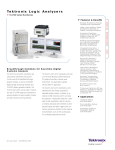
TLA721 with logic analyzer, pattern generator
and digital oscilloscope modules
TLA715 with logic analyzer, pattern generator
and digital oscilloscope modules
TLA600 Series
Affordable Timing and State Logic Analyzers for Your Mainstream Design Needs
2
www.tektronix.com/la
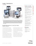
Logic Analyzer with Internal Display
Logic Analyzer with External Display
TLA61x and TLA62x
TLA60x
Tektronix Logic Analyzers
Detailed Product Information
Table of Contents
Logic Analyzers . . . . . . . . . . . . . . . . . . . . . . . . . . . . . . . . . . . .1
TLA Family Selection Guide . . . . . . . . . . . . . . . . . . . . . . . . . . . .4
Tektronix Logic Analyzer Probe Selection Guide . . . . . . . . . . . . . . .6
System Overview . . . . . . . . . . . . . . . . . . . . . . . . . . . . . . . . . . .7
Breakthrough Solutions for Real-time
Digital Systems Analysis . . . . . . . . . . . . . . . . . . . . . . . . . . . . . .9
Find and Analyze your Difficult Real-time
Software Problems . . . . . . . . . . . . . . . . . . . . . . . . . . . . . . . . .11
Enhance Productivity through Familiarity,
Connectivity and Modularity . . . . . . . . . . . . . . . . . . . . . . . . . . .13
Characteristics
TLA700 Series Mainframes . . . . . . . . . . . . . . . . . . . . . . .15
TLA7Axx Logic Analyzer Modules . . . . . . . . . . . . . . . . . . .19
TLA7Nx/Px/Qx Logic Analyzer Modules . . . . . . . . . . . . . . .21
TLA7Dx/Ex Digital Storage
Oscilloscope Modules . . . . . . . . . . . . . . . . . . . . . . . . . . .22
TLA7PG2 Pattern Generator Module . . . . . . . . . . . . . . . . .24
TLA600 Series . . . . . . . . . . . . . . . . . . . . . . . . . . . . . . . .28
Ordering Information
TLA700 Series Mainframes . . . . . . . . . . . . . . . . . . . . . . .32
TLA7Axx Logic Analyzer Modules . . . . . . . . . . . . . . . . . . .33
TLA7Nx/Px/Qx Logic Analyzer Modules . . . . . . . . . . . . . . .35
TLA7Dx/Ex Digital Storage
Oscilloscope Modules . . . . . . . . . . . . . . . . . . . . . . . . . . .39
TLA7PG2 Pattern Generator Module . . . . . . . . . . . . . . . . .40
TLA600 Series . . . . . . . . . . . . . . . . . . . . . . . . . . . . . . . .42
TLA Family Service Options . . . . . . . . . . . . . . . . . . . . . . .43
www.tektronix.com/la
3
Tektronix Logic Analyzers
Detailed Product Information
TLA Family Selection Guide
Applications
TLA6xx
TLA715
TLA721
Timing and State Analysis
Yes
Yes
Yes
Single-processor/Bus Analysis
Yes
Yes
Yes
Real-time Instruction Trace Analysis
Yes
Yes
Yes
Source Code Debug
Yes
Yes
Yes
Performance Analysis
Yes
Yes
Yes
–
Yes
Yes
Yes
Multi-processor/Bus Analysis
Digital Stimulus and Control
–
Yes
Digital Signal Quality Analysis
Yes
Yes
Yes
–
–
Yes
System Validation
TLA Mainframe Selection
Type of Mainframe
Number of Module Slots
TLA6xx
TLA715
TLA721
TLA7XM
Non-modular
Modular
Modular
Expansion – Modular
N/A
2
5
Operating System
6
Microsoft Windows 2000 Professional
N/A
Internal Display Resolution
800x600 (TLA61x/62x only;
TLA60x requires external display)
800x600
Requires external display
N/A
External Display Resolution
1280x1024
1600x1200
1600x1200
N/A
Number of External Displays
1
4 (with two
PCMCIA video adapters)
4 (with two
PCMCIA video adapters)
N/A
Standard Data Window Types
Remote Control with Microsoft COM/DCOM
TLA Logic Analyzer Selection
Channels
Waveform, Listing, Histogram (Performance Analysis), Source Code
Yes
Yes
Yes
N/A
N/A
TLA6xx
TLA7Nx/Px/Qx
TLA7Axx
34, 68, 102, 136 per instrument
34, 68, 102, 136 per module
34, 68, 102, 136 per module
Max Channels per Timebase (merged)
136
272 in TLA715
408 in TLA721
272 in TLA715
680 in TLA721
Max Channels per Mainframe
136
272 in TLA715
680 in TLA721
272 in TLA715
680 in TLA721
Max Channels per System
136
1,768 (with TLA715 and two TLA7XMs)
8,160 (with TLA721 and ten TLA7XMs)
1,768 (with TLA715 and two TLA7XMs)
8,160 (with TLA721 and ten TLA7XMs)
1
13 (with TLA715 and two TLA7XMs)
60 (with TLA721 and ten TLA7XMs)
13 (with TLA715 and two TLA7XMs)
60 (with TLA721 and ten TLA7XMs)
100 MHz std.
200 MHz opt.
100 MHz std.
200 MHz opt.
120 MHz std.
235, 450 MHz opt.
200 MHz
200 MHz
800 MHz
400/200 Mb/s (half/full channels)
400/200 Mb/s (half/full channels)
1,250/900/450 Mb/s
(quarter/half/full channels)
Max Independent Buses per System
State Clock Rate
Max State Clock Rate (half channel mode)
Max State Data Rate
2 GHz (500 ps) with 2 Kb depth
2 GHz (500 ps) with 2 Kb depth
8 GHz (125 ps) with 16 Kb depth
Simultaneous State and Timing
Through Same Probe
MagniVu Timing (all channels, all the time)
Yes
Yes
Yes
Analog Measurements Through Same Probe
No
No
Yes
4
www.tektronix.com/la
Tektronix Logic Analyzers
Detailed Product Information
TLA Logic Analyzer Selection (cont.)
TLA6xx
TLA7Nx/Px/Qx
TLA7Axx
500 MHz (2 ns)/250 MHz (4 ns)
(half/full channels)
500 MHz (2 ns)/250 MHz (4 ns)
(half/full channels)
2 GHz (500 ps)/1 GHz (1 ns)/500 MHz (2 ns)
(quarter/half/full channels)
128/64 Kb to 2/1 Mb
(half/full channels with timestamp)
128/64 Kb to 128/64 Mb
(half/full channels with timestamp)
512/256/128 Kb to 256/128/64 Mb
(quarter/half/full channels with timestamp)
Source Synchronous Clocking
No
No
Yes
Analog Outputs
(four per module – analog MUX)
No
No
Yes
Digital Storage Oscilloscope Capability
TLA7Dx/Ex Modules (Internal)
TDS Oscilloscopes*1 (External)
2&4
2&4
8 (TLA715)
20 (TLA721)
4
52 (with TLA715 and two TLA7XMs)
240 (with TLA721 and ten TLA7XMs)
4
Deep Timing
Memory Depth
Channels per Module
Max Channels per Mainframe
Max Channels per System
Bandwidth
500 MHz & 1 GHz
100 MHz to 6 GHz
Sample Rate
2.5 GS/s & 5 GS/s
1.25 GS/s to 20 GS/s
Vertical Resolution
8-Bits
8-Bits and 9-Bits
Memory Depth
15 Kb
10 Kb to 32 Mb
TLA Pattern Generator Module
TLA7PG2
Channels
64
Max Channels per Bus (merged)
128 (with TLA715) 320 (with TLA721)
Max Channels per Mainframe
128 (with TLA715) 320 (with TLA721)
Max Channels per System
832 (with TLA715 and two TLA7XMs)
3,840 (with TLA721 and ten TLA7XMs)
Pattern Speed (half/full channels)
268/134 MHz
Memory Depth (half/full channels)
Logic Families Supported
512 / 256 Kb to 2 / 1 Mb
CMOS/TTL, ECL, LVCMOS, PECL/LVPECL, LVDS, Variable
*1 For a complete list of currently supported TDS oscilloscopes, please visit our website http://www.tektronix.com/iview.
www.tektronix.com/la
5
Tektronix Logic Analyzers
Detailed Product Information
Tektronix Logic Analyzer Probe Selection Guide
P6810
Logic Analyzer Used
Recommended Use
Attachment to Target System
Probe Type
P6860
P6880
P6417
TLA7AAx Logic Analyzer Modules
TLA7ABx Logic Analyzer Modules
Recommended for
Recommended
most general-purpose
for applications
uses that require
requiring many
maximum flexibility for
channels to be
single-ended or
quickly connected in
differential requirements a small footprint
Probe leadsets
adapt to industry
standard interfaces;
leads spread over
a wide area
P6418
P6434
TLA6xx Logic Analyzers
TLA7Lx/7Mx Logic Analyzer Modules
TLA7Nx/7Px/7Qx Logic Analyzer Modules
Recommended for
applications requiring
many differential
channels to be
quickly connected in
a small footprint
Recommended
for most
general-purpose
uses that require
maximum flexibility
Recommended
for most
general-purpose
uses
Recommended for
applications
requiring many
channels to be
quickly connected in
a small footprint
Connectorless
Connectorless
“compression” contact “compression” contact
(Adapter for
(Adapter for
Mictor connector
Mictor connector
available)
available)
Probe leadsets
adapt to industry
standard interfaces;
leads spread over
a wide area
Probe leadsets
adapt to industry
standard interfaces
AMP Mictor 34channel connector
(Adapter to use P6434
with P6860/80
high-density
compression land
footprint available)
General-purpose,
34-channel
active probe
High-density,
34-channel
active probe
High-density,
34-channel
active differential
probe
General-purpose,
17-channel
passive probe
General-purpose,
17-channel
passive probe
High-density,
34-channel
passive probe
AMP Mictor
connector required
Pin Spacing Supported
0.100 in. and 2 mm
N/A
N/A
0.100 in.
0.100 in.
N/A
Logic Signals Supported
Differential Clock
Differential Data
Differential Clock
Single-ended Data
Differential Clock
Differential Data
Simultaneous State/
Timing to:
800 MHz/
8 GHz
800 MHz/
8 GHz
800 MHz/
8 GHz
200 MHz/
2 GHz
200 MHz/
2 GHz
200 MHz/
2 GHz
Simultaneous State/
Timing/Analog to:
800 MHz/
8 GHz/2 GHz
800 MHz/
8 GHz/2 GHz
800 MHz/
8 GHz/2 GHz
N/A
N/A
N/A
300 mVp-p
Vmax – Vmin ≥150 mV
300 mVp-p
Vmax – Vmin ≥150 mV
300 mVp-p
Vmax – Vmin ≥150 mV
500 mVp-p
N/A
500 mVp-p
N/A
500 mVp-p
N/A
1.2 pF/20 kΩ
to Ground
0.7 pF/20 kΩ
to Ground
0.7 pF/20 kΩ
to Ground
Minimum Signal Amplitude
Minimum Single-ended
Minimum Differential
Probe Load AC/DC
Notes
6
www.tektronix.com/la
Single-ended Clock
Single-ended Clock
and Data (Differential and Data (Differential
signal adapters
signal adapters
available)
available)
2 pF/20 kΩ
2 pF/20 kΩ
to 2.2 V
to 2.2 V
(Low-voltage adapters (Low-voltage adapters
that work with
that work with
low-voltage signals
low-voltage signals
are available)
are available)
Works with a
No connector required: No connector required:
Works with a
wide range of
only land pads
only land pads
wide range of
industry-standard
required to be laid
required to be laid
industry-standard
accessories for
out on target system out on target system
accessories for
flexible attachment
PCB for 17 and/or
PCB for 17 and/or
flexible attachment
to your target system
34 channels.
34 channels.
to your target system
Please refer to
Please refer to
P6860/6880 probe
P6860/6880 probe
design guide
design guide
Single-ended Clock
and Data
2 pF/20 kΩ
to 2.2 V
Works with a
Requires AMP
wide range of
Mictor connector
industry-standard
to be installed on
accessories for
target system PCB for
flexible attachment
every 34 channels.
to your target system
Please refer to
P6434 probe manual
Tektronix Logic Analyzers
Detailed Product Information
System Overview – Features and Benefits
System Capability
Flexible Acquisition and Stimulus
– Logic Analyzer Acquisition Modules
– Digital Oscilloscope Modules
– Pattern Generator Modules
– Integrated View (iView)
– TLA600 Series offers similar measurement capability as modular series in fixed channel widths for mainstream digital designers.
– TLA700 Series modular approach allows you to select the optimum combination of stimulus and acquisition to fit your
performance, feature, and budget requirements.
– System software, setup information, data files common to both TLA600 and TLA700 instruments enabling easy data and file
sharing between groups or instruments.
– Real-time correlated data views provide system level visibility from high-level source code to high-speed state & timing to analog
characteristics of digital signals.
– Utilize industry leading TDS oscilloscopes to view time-correlated analog and digital data in the same TLA display.
Enhanced TLA700 Mainframe Hardware
– Pentium® III processor, with up to 60 GB hard disk, 512 MB system RAM, and CDRW provides a powerful platform for data analysis.
– Multiple monitor support, each with up to 1600 x 1200 resolution, to see more data.
Expansion Capability
– By connecting up to 10 expansion mainframes you can simultaneously view time-correlated data for multi-bus designs (up to 60
individual buses) using up to 8160 channels, each with up to 256 Mb memory depth.
TLAVu, PatGenVu Offline Analysis
– Utilize this free application software to analyze data or create setups on a separate PC.
Upgrade, trade-in capability
– Upgrade kits offer upgrades to system RAM, hard disk, TLA application software, operating system software, iView capability and
controllers to help protect investments and allow test equipment to change as measurement needs change.
– PowerFlex™ program provides customer installable upgrades on measurement modules including faster state speed and additional
memory depth to allow the flexibility to upgrade instrumentation over time.
– Mainframe and module trade-in programs protect investments by providing discounts on future measurement equipment.
Measurement Modules and Key Interface Features
TLA7Axx Logic Analyzer Modules
– 8 GHz MagniVu™ timing, 120 to 800 MHz state acquisition (up to 1.25 Gb/s data rate), 128 Kb to 256 Mb memory depth capability
TLA7Nx/Px/Qx Logic Analyzer Modules
– 2 GHz MagniVu timing, 100 to 200 MHz state acquisition (up to 400 Mb/s data rate), and 64 Kb to 128 Mb memory depth
capability provide the tools necessary to address a wide range of digital designs.
TLA6xx Logic Analyzers
– 2 GHz MagniVu timing, 100 to 200 MHz state acquisition (up to 400 Mb/s data rate), and 64 Kb to 2 Mb memory depth capability
provide analysis tools to address mainstream digital design and debug.
TLA7Dx/Ex Digital Oscilloscope Modules
– 500 MHz and 1 GHz, 2.5 and 5 GS/s, 2 and 4 channel oscilloscope modules provide analog trace capture time-correlated with
digital data.
TLA7PG2 Pattern Generator Module
– 64 Channel, up to 268 MHz, and up to 2 Mb vector depth along with probes supporting multiple logic levels and variable delays
provides a flexible solution for device simulation and hardware verification.
Integrated View (iView)
– Up to 6 GHz, 20 GS/s, 4 channel TDS oscilloscope data automatically time-correlated with TLA digital data on the logic analyzer
display.
provide enough power to capture and debug the fastest and most complex high-speed digital designs.
– Route any four logic analyzer input channels to the four analog signal output BNC connectors on the TLA7Axx module. Connect an
internal oscilloscope module or external TDS oscilloscope to view analog signal information.
– Analog signal outputs are always active allowing visibility of analog information at all times.
MagniVu Technology
– MagniVu acquisition technology provides up to 125 ps timing resolution simultaneous with state acquisition on all channels all
the time.
www.tektronix.com/la
7
Tektronix Logic Analyzers
Detailed Product Information
Measurement Modules and Key Interface Features (cont.)
EasyTrigger
– Graphical and textual trigger descriptions to easily define a trace event.
– Trigger interface quickly sets up the powerful trigger state machine to save time in debug efforts.
– Over 100 pre-defined categorized trigger programs to choose from.
PowerTrigger
– Programmable trigger interface for creating specialized triggers to aid in tracking down elusive problems.
Triggering
– State-based trigger machine with 16 states available to aid in finding complex problems in digital designs.
– Decrement counters.
– 16 transition recognizers.
– “Snapshot” trigger that loads a current state on the fly for use later in a trigger program.
– Separate MagniVu™ trigger action to view high-speed timing information where it is needed most.
Processor and Bus Support
– Acquire real-time trace of processor or bus cycles without interfering with bus operation.
– High-level source code analysis correlates high-level language with real-time trace.
– Symbolic debug with unlimited number of symbols. Object file formats supported include IEEE695, OMF51/86/166/286/386, COFF,
Elf/Dwarf 1 & 2, Elf/Stabs, and TSF (Tektronix Symbol Format).
– Monitor and correlate multiple processors or buses simultaneously with the TLA700 series logic analyzer.
Direct Links to EDA Tools
– Use captured logic analysis data to generate simulation vectors.
– Easily perform hardware verification by comparing captured data with simulation data.
Documentation, Remote Programming
Documentation Capability
– Utilize the pre-installed SnagIt™ graphical capture software to save graphics as TIF, PCX, JPG, BMP, GIF files or send them directly
to a local or networked printer.
– Capture any window, region, or object on the screen.
– Start SnagIt directly from the TLA application software.
Data Export
– Export data in ASCII, binary, or Tektronix .tla file formats for offline use.
Remote Programming with Microsoft’s
COM/DCOM Interface
– Control logic analyzer operation using TLA Programmatic Interface (TPI) providing automated operation of the TLA.
TLA Application Software
Microsoft Windows 2000 Professional
– Open Windows interface provides a familiar user interface and network connectivity.
Multiple Analysis Windows
– View data in waveform, listing, source, or histogram windows to better analyzer cross-domain data from a target system.
– Lock multiple windows of data together for improved analysis of correlated data.
Global Cursors and Marks
– Utilize multiple cursors and user-definable marks to aid in the analysis of data across multiple data windows.
– Lock cursors together in data windows providing constant offsets to make measurements quickly.
Flexible Data Views
– Quickly zoom in on areas of interest, resize waveforms, overlay analog and digital waveforms, make analog measurements, label
waveforms, and color code symbols to customize the display for easy analysis of complex digital systems.
Web-Enabled System
– Quickly and easily run a TLA over a network from a workstation or over the Internet.
– Transfer data over the network for offline analysis using TLAVu.
Network Security
8
www.tektronix.com/la
– Utilize the built-in security of Windows 2000 Professional to protect the data integrity of your files.
Tektronix Logic Analyzers
Detailed Product Information
Breakthrough Solutions for Real-time Digital Systems Analysis
MagniVu Acquisition
Technology – A Breakthrough for
Logic Analyzers
The TLA Family includes a wide selection of logic analyzers with unprecedented measurement capabilities.
At the heart is a breakthrough acquisition technology
called MagniVu. MagniVu is a super-high-speed sampling architecture that dramatically changes the way
logic analyzers work and enables them to provide
startling new measurement capabilities.
Capturing and Correlating
Elusive Faults
Complex system problems, especially intermittent
ones, that show up late in product development can
derail the most carefully planned schedules. TLA
logic analyzers keep embedded hardware and software designers on track by providing a non-intrusive tool to monitor, capture and analyze these elusive real-time system problems. By capturing and
correlating multiple views of data, including analog,
As a digital design engineer, you’re dealing with
These high-performance, low-capacitance (0.7 pF
faster edge speeds and tighter timing margins that
total capacitance), active logic analyzer probes pro-
create more signal integrity issues than ever before.
vide cleaner signals and reduce layout complexity
The Tektronix TLA Family of logic analyzers delivers
and cost. The probes support both single-ended and
a wide range of powerful solutions. The TLA’s iView
differential signals with the same pattern.
capability enables you to observe how the digital
This is the kind of performance you expect from
World’s Fastest Logic Analyzer
Modules
and analog worlds interact. Connecting an external
Tektronix – with productivity and connectivity tools
These remarkable, high performance logic analyzer
oscilloscope to your TLA delivers an integrated
that will greatly shorten your time to market.
modules plug into your existing Windows 2000
For every task you face, the TLA’s innovative
MagniVu technology provides 125 ps timing
resolution on all channels – all the time – through
the same probe. Our industry-leading logic analyzers provide up to 800 MHz state acquisition with
1.25 Gb/s data rate for advanced processors
and buses. And simultaneous state, high-speed
timing and analog analysis pinpoints elusive faults.
can quickly identify the source of a problem, wherever it is.
Professional logic analyzer mainframe to deliver
measurement solution that can capture and display
both domains in a single time-correlated view.
digital and embedded software, the design team
Timing Resolution
unmatched accuracy, speed, and ease-of-use for
Whether you are debugging a high-performance
debug and verification work. You may also route the
computer or part of an embedded system, the timing
analog signal of any 4 logic analyzer channels to an
parameters of your designs demand sub-nanosec-
oscilloscope. And all of the modules offer PowerFlex
ond resolution. Logic analyzers that only offer 4 ns
customer-installable memory and speed upgrades
timing resolution are simply not adequate to capture
to satisfy future needs.
today’s complex problems. Nobody wants to trade
off channels for resolution, buy separate timing
modules, or trade up to more expensive hardware to
get the resolution today’s designs require. The TLA
The TLA Family also works with the world’s first connectorless logic analyzer probes, only from Tektronix.
Family with MagniVu acquisition provides 8 GHz
(125 ps) timing resolution on every channel.
www.tektronix.com/la
9
Tektronix Logic Analyzers
Detailed Product Information
Digital and Analog Through
a Single Probe
Stimulus for Functional
Verification
Here is an innovation the world of test and meas-
System verification often requires you to stimulate
urement has needed: simultaneous analog and digi-
your designs with ideal or faulty digital patterns. The
tal measurements through a single logic analyzer
TLA pattern generator controls your circuit at full
probe. No more having to get out your oscilloscope
speed or steps through individual states. With the
probe for analog information. Now, one probe does
combination of logic analyzer and pattern generator
it all. You get quick signal access, with no double-
modules, you can control and monitor real-time
probing, no double-loading, and no more trying to
system operation.
handle two probes at once. Nothing is easier, or
yields cleaner signals.
The Integrated View
Today almost every design is a high-speed design,
with fast clock edges and data rates on even the
most common IC devices. So nearly every design
requires signal integrity analysis. Engineers need to
see the analog characteristics of high-speed digital
signals in relation to complex digital events in the
Find Digital Signal Integrity
Problems
circuit. The solution: iView.
Faster edge speeds and tighter timing margins are
The iView (Integrated View) capability seamlessly
integrates data from Tektronix TLA logic analyzers
creating more signal integrity issues than ever
before. Overshoot, ringing, crosstalk, reflections and
ground bounce can cause glitches and intermittently
alter the timing of otherwise stable signals.
Connecting an external digitizing oscilloscope to
your TLA system with Integrated View capability
provides up to 6 GHz analog signal bandwidth,
along with the hundreds of logic signals you are
already monitoring. Since the external Tektronix digital oscilloscope data is automatically time-corre-
Digital/analog overlay.
P6860/80 Connectorless Logic
Analyzer Probes
and TDS oscilloscopes allowing designers to transfer
analog waveforms from the oscilloscope to the logic
analyzer display and automatically time-correlate
Tektronix offers a family of new high-performance,
them. The result: engineers can quickly track down
low-capacitance, active logic analyzer probes which
elusive signal integrity problems in their designs.
do away with add-on connectors and attach directly
The new iView package includes TLA Application
to printed circuit boards. These connectorless
Software and an interconnect cable to integrate
probes use Silicon Germanium (SiGe) technology to
TLA600 or TLA700 Series logic analyzers with a
provide high-quality signal measurements.
wide range of external TDS Series oscilloscopes.
lated, the iView capability lets you easily observe
iView capability couples selected Tektronix TDS
the quality of critical signals alongside the original
family oscilloscopes with TLA Series logic analyzers,
behavior they affect.
producing a solution that shows, on the same logic
analyzer display, time-correlated views of both digi-
Probing Solutions
tal and analog waveforms.
Whether you are building high-density test connec-
Set up is easy through the use of an external oscil-
tors into your verification platform, using a config-
loscope "wizard" in the TLA Series logic analyzer
ured probe adapter for popular microprocessors or
user interface that guides the user through set up
buses, or just hooking up signals as you need more
and connection. No user calibration or calibration
visibility, Tektronix has the probing solution.
fixture is required. And, once set up is completed,
the iView capability is completely automated.
10 www.tektronix.com/la
Tektronix Logic Analyzers
Detailed Product Information
Find and Analyze your Difficult Real-time Software Problems
Source Code Debugging
Tektronix logic analyzers provide real-time debug
visibility by nonintrusively capturing instruction execution and system signals. This maximizes source
code debugging productivity by linking the source
code to instruction trace history, correlated to sys-
➤
tem hardware signals.
Source code debugging.
Real-time Instruction Trace
TLA software includes disassembly capability for
analyzing every bus transaction and determining
what instructions were read across the bus. The
software then places the assembly mnemonic in
the display with the associated address. This disassembly display enables you to view the data at dif-
➤
ferent levels of abstraction.
The state display provides a view of raw hex data.
Real-time instruction trace.
The hardware display shows every bus cycle type
with instructions. The software display filters out
the noninstruction cycles. The flow control shows
only instructions that cause a change in the program flow, and the subroutine display shows only
the entry and exit points to subroutines.
➤
Real-time Correlation
to Hardware
With the TLA’s time stamp always running, every
acquisition and every bus cycle has a unique
125 ps time stamp. Because of this capability, the
Real-time correlation to hardware.
TLA700 Series provides precision time correlation
across ALL the modules in the TLA700 system,
even across expansion mainframes. This allows you
to see how the event on one bus affects the operation of another bus in the system.
www.tektronix.com/la 11
Tektronix Logic Analyzers
Detailed Product Information
Processor Support
TLA processor support provides an easy-to-use
acquisition and analysis package. The software
automatically sets up the TLA, including assigning
channels and programming the clocking state
System Performance Analysis
This feature lets you nonintrusively monitor, capture and analyze the system’s real-time software and hardware
performance. Using the performance analysis tool, you can quickly identify software and hardware areas to
be optimized.
machine for your particular processor. This enables
the TLA to acquire every bus cycle quickly and
seamlessly in real time. Many of the support packages provide a probe adapter using the Tektronix
P6434 high-density probe, to connect to the
processor or bus being analyzed. The probe provides quick connection to 34 channels, and eliminates possible human error.
Tektronix Embedded Systems Tool Partners
Over 25 industry-leading Embedded Systems Tools Partners deliver a wide range of development and debug
solutions that work with Tektronix logic analyzers. Software development tools such as software debuggers and
emulators running on the TLA logic analyzer provide you with the complete system control and insight critical to
verifying, debugging and optimizing your system.
12 www.tektronix.com/la
Tektronix Logic Analyzers
Detailed Product Information
Enhance Productivity through Familiarity, Connectivity and Modularity
Familiarity
Work in a familiar, open and connected environment with the Microsoft Windows operating system, the platform upon which the entire TLA Family
is based.
– TLA applications operate like any other PC
application
– Familiar Microsoft Windows toolbar and desktop
Remote Operation
You can remotely operate the TLA user interface
from another Windows or UNIX workstation, and
customize the TLA user interface to fit your
working style.
– Control your TLA remotely using a Web browser
Familiarity.
– Develop your own custom tools that access TLA
data using the TLA Programmatic Interface (TPI)
based upon Microsoft COM/DCOM
– Remotely view your target system operation
across the network using a Webcam from the
comfort of your office
Remote operation.
www.tektronix.com/la 13
Tektronix Logic Analyzers
Detailed Product Information
Advanced data analysis via Microsoft Excel.
Advanced Data Analysis
Up to 8,160 logic analyzer channels acquire
real-time data.
The TLA Family’s remote control command set,
based on Microsoft COM/DCOM technology, interfaces seamlessly with advanced Windows applications – such as Microsoft Excel, shown at right – to
provide powerful advanced data analysis and the
graphical presentation of results either directly on
the TLA, or remotely over a network.
Offline Data Analysis
The TLAVu™ Offline Data Viewer increases productivity. From their desks, designers can view data
Connectivity.
and create setups for the next time they are in the
Connectivity and Modularity
Expandability.
All models of the TLA family (except the TLA60x)
come standard with dual display capability for
extended desktop viewing. These models also feature an internal CD-R/W, hard disk and PC card
slots for expansion (such as for a LAN connection).
Other industry-standard PC connections include
SVGA, printer, serial, USB, mouse and keyboard.
Trigger in/out connections provide an interface to
other external instrumentation for coordinating
measurement results.
The replaceable hard disk is standard on the TLA700
Series, ideal for security or enabling individual team
members to store personal setups and data.
The TLA700 Series is card-modular so you can
configure the number and type of logic analyzer,
pattern generator or digitizing oscilloscope modules
to meet your requirements.
14 www.tektronix.com/la
lab. TLAVu software is a version of the TLA software that installs on a PC running Windows 95, 98,
Expandable to Meet
Future Needs
A variety of flexible options, such as new products,
field upgrade kits and special programs are available to enhance the measurement capabilities of
your TLA.
NT4, ME, XP or 2000.
Tektronix Logic Analyzers
Detailed Product Information
Characteristics
TLA700 Integral Controls
(TLA715 only)
Front-Panel Display –
Size: 10.4 in. diagonal.
Type: Active-matrix color TFT LCD with backlight.
Resolution: 800x600.
Colors: 16.8 M (true color).
Simultaneous Display Capability – Both the
front-panel and one external display can be used
simultaneously at 800x600 resolution.
Front-panel Knobs – Special function knobs for
instrument control.
Front-panel QWERTY Keypad – Mini-QWERTY
keypad and Hex keypad.
Front-panel Pointing Device – Trackball.
TLA700 External Peripheral
Interfaces (TLA715 and TLA721)
External Display Port Type –
(2) Female DB15 connectors.
For configurations beyond ten TLA7XM expansion
mainframes, please contact your local Tektronix
account manager.
TLA700 Series
Mainframes
General (TLA715,
TLA721, TLA7XM)
Instrument Slots –
TLA715: Holds 4 single-wide or 2 double-wide
modules.
TLA721: Holds 10 single-wide or 5 double-wide
modules.
TLA7XM: Holds 12 single-wide or 6 double-wide
modules.
Quantity of TLA7XMs – The TLA700 Series
Mainframes can support multiple TLA7XM
mainframes.
TLA715: Up to two TLA7XM mainframes can be used
providing 13 dual/26 single instrument slots. *1 *2
TLA721: Up to ten TLA7XM mainframes can be used
providing 60 dual/120 single instrument slots. *1 *2
Mainframe
LA *3
PG *3
DSO *3
Max channels
per module
136 ch.
64 ch.
4 ch.
TLA715
1,768
832
52
TLA721
8,160
3,840
240
*1 TLA7XM
TLA700 PC Characteristics
(TLA715 and TLA721)
Operating System – Microsoft Windows
2000 Professional.
External Display Resolution – Up to 1600x1200
noninterlaced at 256 colors, for both primary and
secondary displays.
External Display Compatibility – DDC2B
(dynamic display configuration 2).
External Keyboard Port Type – PS2 mini-DIN.
External Mouse Port Type – PS2 mini-DIN.
Chipset – Intel 815E.
Parallel Interface Port Type – IEEE 1284-C
connector (comes standard with adapter to female
DB25 connector).
DRAM –
TLA715: 256 MB SDRAM (512 MB with Opt. 1S).
TLA721: 512 MB SDRAM.
Parallel Interface Modes – Centronics mode,
EPP (Extended Parallel Port), ECP (Microsoft highspeed mode).
Display Memory – 4 MB.
Serial Interface Port Type – Male DB9.
Dual Monitor Support – 1600x1200 Resolution.
PC Card (CardBus) Slot Types – Two slots, two PC
Card Type I/II or one PC Card Type III.
Processor – Intel Pentium III.
Sound – Built-in PC speaker transducer; multimedia
sound can be added via PC Card interface.
USB Port – Two (2).
Replaceable Hard Disk Drive –
TLA715: 10 GB (30 GB with Opt. 1S).
TLA721: 30 GB.
CD ROM – Internal 8/4/32 CD-RW.
Floppy Disk Drive – Built-in 3.5 in. 1.44 MB drive.
Expansion Module occupies one single-wide slot in both the TLA715/TLA721 mainframes and the TLA7XM expansion mainframe.
*2 Using
a TLA7XM expansion mainframe with an existing TLA714/TLA720 mainframe requires Version 4.0 or higher TLA application software.
TLA720 benchtop mainframes, S/N: B019999 and lower, require TLA7UP Option 09 TLA720 Benchtop Mainframe Upgrade. Please refer to the
TLA Upgrade Guide for further details.
*3 All
Example of TLA721 with ten TLA7XM Mainframes.
logic analyzer (LA), pattern generator (PG) and digitizing oscilloscope (DSO) modules are dual-wide or occupy two single-wide slots.
www.tektronix.com/la 15
Tektronix Logic Analyzers
Detailed Product Information
Integrated View
(iView) Capability
TLA Mainframe Configuration Requirements –
TLA714/720/715/721 Series mainframes.
TLA App S/W V 4.1 or greater.
256 MB DRAM Minimum, 512 MB recommended.
TDS Configuration Requirements – TDS3GM
GPIB/RS232 Interface Module required for iView
capability on any TDS3000 series. TDS3GV
GPIB/RS232/VGA Interface Module required for
iView capability on any TDS3000B series. If using
iView with TDS6604, order a TCA-BNC connector
to be compatible with a BNC cable run from a
TLA7Axx module analog output.
Number of TDS Oscilloscopes that Can
be Connected to a TLA System – 1.
External Oscilloscopes Supported –
TDS3012, TDS3014, TDS3032, TDS3034,
TDS3052, TDS3054.
TDS3012B, TDS3014B, TDS3032B, TDS3034B,
TDS3052B, TDS3054B.
TDS5052, TDS5054, TDS5104.
TDS6604.
TDS7054, TDS7104, TDS7154, TDS7404.
TDS684C, TDS694C.
CSA7154, CSA7404.
TDS754C, TDS784C, TDS724D, TDS754D,
TDS784D, TDS794D.
TLA715 Portable Mainframe.
TLA Connections – USB, Trigger In, Trigger Out,
Clock Out.
TDS Connections – GPIB, Trigger In, Trigger Out,
Clock In (when available).
Setup – iView external oscilloscope wizard
automates setup.
Data Correlation – After TDS oscilloscope acquisition
is complete, the data is automatically transferred
to the TLA and time correlated with the TLA
acquisition data.
TLA721 Benchtop Mainframe.
Deskew – TDS and TLA data is automatically
deskewed and time correlated when using the
iView external oscilloscope cable.
iView External Oscilloscope Cable Length – 2 m.
TLA7XM Expansion Mainframe.
16 www.tektronix.com/la
Tektronix Logic Analyzers
Detailed Product Information
TLA715 Portable Mainframe.
TLA715 Series with TDS7000 Series oscilloscope.
Symbolic Support
Number of Symbols/Ranges – Unlimited (limited only
by amount of virtual memory available on TLA).
Object File Formats Supported –
IEEE695
OMF 51, OMF 86, OMF 166, OMF 286,
OMF 386
COFF
Elf/Dwarf 1 and 2
TLA721 and TLA7XM Benchtop and Expansion Mainframes.
Elf/Stabs
TSF (if your software development tools do not
generate output in one of the above formats,
TSF or the Tektronix symbol file, a generic ASCII
file format is supported. The generic ASCII file
format is documented in the TLA User Manual).
If a format is not listed, please contact your
local Tektronix representative.
External Instrumentation
Interfaces
System Trigger Output – Asserted whenever a
system trigger occurs (TTL-compatible output, backterminated into 50 Ω).
TLA721 and TLA7XM Benchtop and Expansion Mainframes with TLA721/TLA7XM Rackmount Kit.
System Trigger Input – Forces a system trigger
(triggers all modules) when asserted (TTL-compatible,
edge-sensitive, falling-edge latched).
External Signal Output – Can be used to drive
external circuitry from a module’s trigger mechanism
(TTL-compatible output, back-terminated into 50 Ω).
External Signal Input – Can be used to provide an
external signal to arm or trigger any or all modules
(TTL-compatible, level-sensitive).
P6041 External Signal Cable Length –
(SMB to BNC adapter cable, two each TLA721 only)
1.1 m (42 in.).
www.tektronix.com/la 17
Tektronix Logic Analyzers
Detailed Product Information
K4000 Instrument Cart.
Environmental
Temperature –
Operating: +5°C to +50°C.
Nonoperating: –20°C to +60°C.
LACART Instrument Cart (adjustable probe skyhook not shown).
Power
Physical Characteristics
TLA715 –
Voltage range/frequency: 90-250 VAC at 45-66 Hz.
100-132 VAC at 360-440 Hz.
Input current: 6 A maximum at 90 VAC (70 A surge).
Power consumption: 600 W maximum.
TLA715 Portable
Dimensions
Height
Width
Depth
Weight
Net (w/o modules)
Shipping (typical)
TLA721 and TLA7XM –
Voltage range/frequency: 90-250 VAC at 45-66 Hz,
100-132 VAC at 360-440 Hz.
Input current: 16.5 A maximum at 90 VAC (70 A surge).
Power consumption: 1,450 W maximum.
18 www.tektronix.com/la
mm
235
432
455
kg
11.4
25.5
in.
9.25
17
17.5
lb.
25
56
TLA721 Benchtop & TLA7XM Expansion
Dimensions
mm
in.
Height
346
13.65
Width
425
16.7
Depth
673
26.5
Weight
kg
lb.
Net (w/o modules)
22.7
50
Shipping (typical)
51.8
114
Humidity –
20% to 80%.
Operating: ≤30°C; 80% relative humidity
(29°C maximum wet bulb temperature).
Nonoperating: 8% to 80% (29°C maximum wet
bulb temperature).
Altitude –
Operating: –1,000 ft. to 10,000 ft. (–305 meters
to 3,050 meters).
Safety – UL3111-1, CSA1010.1, EN61010-1,
IEC61010-1. B
Tektronix Logic Analyzers
Detailed Product Information
Input Characteristics
(with P6810, P6860 or
P6880 probes)
Capacitive Loading – 0.7 pF typical clock/data;
(1.0 pF for P6810 in group configuration).
Threshold Selection Range –
From –2.0 V to +4.5 V in 10 mV increments.
Threshold presets include TTL (1.5 V), CMOS (1.65 V),
ECL (–1.3 V), Differential (0 V) and user-defined.
Threshold Selection Channel Granularity –
Separate selection for each of the clock/qualifier
channels and one per group of 16 data channels
for each 34 channel probe.
Threshold Accuracy (including probe) –
±(25 mV + 1%).
Input Voltage Range –
Operating: –2.5 V to 5.0 V.
Nondestructive: ±15 V.
Minimum Input Signal Swing – 300 mV or 25% of
signal swing, whichever is greater (single-ended);
Vmax – Vmin > 150 mV (differential).
Input Signal Minimum Slew Rate –
200 mV/ns typical.
TLA7Axx Logic Analyzer
Modules
General
Number of Channels (all channels are acquired
including clocks) –
TLA7AA1: 34 channels (2 are clock channels).
TLA7AA2, TLA7AB2: 68 channels (4 are
clock channels).
TLA7AA3: 102 channels (4 are clock and 2 are
qualifier channels).
TLA7AA4, TLA7AB4: 136 channels (4 are clock and
4 are qualifier channels).
Channel Grouping: No limit to number of groups or
number of channels per group (all channels can be
reused in multiple groups).
TLA700 Module “Merging” –
Five 102-channel or 136-channel modules can be
“merged” to make up to a 680-channel module.
Merged modules exhibit the same depth as the lesser
of the five individual modules.
Word/setup-and-hold/glitch/transition recognizers
span all five modules. Range recognizers limited to
three module merge. Only one set of clock connections
is required.
Time Stamp – 51-Bits at 125 ps resolution
(3.25 days duration).
Clocking/Acquisition Modes – Internal, internal 2X,
internal 4X, external, external 2X, external 4X, source
synchronous. 8 GHz MagniVu™ high-speed timing is
available simultaneous with all modes.
Number of Mainframe Slots Required per
TLA700 Module – 2.
State Acquisition
Full Channel
Half Channel
Quarter Channel
120 MHz Standard
235 MHz/235 Mb/s or
120 MHz/240 Mb/s (DDR)
235 MHz/470 Mb/s
235 MHz Optional
450 MHz/450 Mb/s or
235 MHz/470 Mb/s (DDR)
450 MHz/900 Mb/s
450 MHz Optional
800 MHz/800 Mb/s or
450 MHz/900 Mb/s (DDR)
625 MHz/1.25 Gb/s
State Acquisition
Characteristics (with P6810,
P6860 or P6880 probes)
State Memory Depth with Timestamps –
(quarter/half/full channels) 512/256/128 Kb,
2 M/1 M/512 Kb, 8/4/2 Mb, 32/16/8 Mb,
128/64/32 Mb, 256/128/64 Mb per channel.
Setup and Hold Time Selection Range – From 8 ns
before, to 8 ns after clock edge. Range may be
shifted towards the setup region by 0 ns [+8, –8] ns,
4 ns [+12, –4] ns, or 8 ns [+16, 0] ns.
Setup-and-hold Window –
All Channels: 625 ps typical.
Single Channel: 500 ps typical.
Minimum Clock Pulse Width – 400 ps.
Active Clock Edge Separation – 400 ps.
Demux Channel Selection – Channels can be
demultiplexed to other channels through user
interface with 8 channel granularity.
Source Synchronous Clocking – Up to four
“Fast Latches” per module (20 max per 5-way
merge) to strobe source-synchronous buses into
TLA7Axx modules.
Four sets of any predefined “Fast Latches” may be
combined with qualification data and data pipelining
to store four independent source-synchronous
data buses.
Two “Fast Latches” may be combined to address
DDR applications.
www.tektronix.com/la 19
Tektronix Logic Analyzers
Detailed Product Information
Trigger Event Types – Word, group, channel,
transition, range, anything, counter value, timer value,
signal, glitch, setup-and-hold violation, snapshot.
Trigger Action Types – Trigger module, trigger all
modules, trigger main, trigger MagniVu, store,
don’t store, start store, stop store, increment counter,
decrement counter, reset counter, start timer,
stop timer, reset timer, snapshot current sample,
goto state, set/clear signal, do nothing.
Maximum Triggerable Data Rate – 1250 Mb/s.
Trigger Sequence Rate – DC to 500 MHz (2 ns).
Counter/Timer Range – 51 Bits each (>50 days
at 2 ns).
Counter Rate – DC to 500 MHz (2 ns).
Timer Clock Rate – 500 MHz (2 ns).
Counter/Timer Latency – 2 ns.
Range Recognizers – Double bounded (can be as
wide as any group, must be grouped according to
specified order of significance).
Differential inputs.
Timing Acquisition
Characteristics (with P6810,
P6860 and P6880 probes)
Analog Acquisition
Characteristics (with P6810,
P6860 and P6880 probes)
MagniVu Timing – 125 ps max, adjustments to
250 ps, 500 ps, 1 ns, and 2 ns.
Bandwidth – 2 GHz typical.
MagniVu Timing Memory Depth – 16 Kb per
channel, with adjustable trigger position.
DC Offset – ±1 mV.
Deep Timing Resolution (quarter/half/full
channels) – 500 ps/1 ns/2 ns to 50 ms.
Deep Timing Resolution with Glitch Storage
Enabled – 4 ns to 50 ms.
Deep Timing Memory Depth (quarter/half/full
channels with timestamps and with or without
transitional storage) – 512/256/128 Kb,
2 Mb/1 Mb/512 Kb, 8/4/2 Mb, 32/16/8 Mb,
128/64/32 Mb, 256/128/64 Mb per channel.
Deep Timing Memory Depth with Glitch Storage
Enabled – Half of default main memory depth.
Attenuation – 10x, ±1%.
Channels Demultiplexed – 4.
Run/Stop Requirements – None, analog outputs
are always active.
iView Analog Outputs – Compatible with any
internal TLA7Dx/Ex DSO module or supported TDS
external oscilloscope.
iView Analog Output BNC Cable – Low loss,
10x, 36-in.
Trigger Characteristics
Independent Trigger States – 16.
Channel-to-channel Skew – 250 ps typical.
Maximum Independent If/then Clauses per
State – 16.
Minimum Recognizable Pulse/Glitch Width (single
channel) – 500 ps (P6810, P6860, P6880) 1 ns.
Maximum Number of Events per If/then
Clause – 8.
Minimum Detectable Setup/Hold Violation –
250 ps.
Maximum Number of Actions per If/then
Clause – 8.
Minimum Recognizable Multi-channel Trigger
Event – Sample period + 400 ps.
Maximum Number of Trigger Events –
18 (2 counter/timers plus any 16 other resources).
Number of Word Recognizers – 16.
Number of Transition Recognizers – 16.
Number of Range Recognizers – 4.
Number of Counter/Timers – 2.
20 www.tektronix.com/la
Setup-and-hold Violation Recognizer Setup Time
Range – From 8 ns before to 7 ns after clock edge in
125 ps increments. This range may be shifted
towards the positive region by 0 ns, 4 ns, or 8 ns.
Setup-and-hold Violation Recognizer Hold Time
Range – From 7 ns before to 8 ns after clock edge
in 125 ps increments. This range may be shifted
towards the positive region by 0 ns [+8, –8] ns,
4 ns [+12, –4] ns, or 8 ns [+16, 0] ns.
Trigger Position – Any data sample.
MagniVu Trigger Position – MagniVu position can
be set from 0% to 60% centered around the
MagniVu trigger.
Storage Control (data qualification) – Global
(conditional), by state (start/stop), block, by trigger
action, or transitional. Also force main prefill
selection available.
Physical Characteristics
Dimensions
Height
Width
Depth
Weight
Net
Shipping
mm
262
61
381
kg
3.1
6.3
in.
10.3
2.4
15
lb.
6.7
13.7
P6810 Probe Cable Length – 1.8 m (6 ft.).
P6860 Probe Cable Length – 1.8 m (6 ft.).
P6880 Probe Cable Length – 1.8 m (6 ft.).
All three probes have the same electrical length
and are delay matched.
Tektronix Logic Analyzers
Detailed Product Information
State Memory Depth with Timestamps – 64 Kb,
256 Kb, 1 Mb, 4 Mb, 16 Mb or 64 Mb per channel.
Setup-and-hold Time Selection Range –
From 8.5 ns before, to 7.0 ns after clock edge.
Setup-and-hold Window – 2.0 ns typical.
Minimum Clock Pulse Width – 2 ns.
Active Clock Edge Separation – 5 ns.
Demux Channel Selection – Channels can be
demultiplexed to other channels through user
interface with 8-channel granularity.
Timing Acquisition
Characteristics (with P6417,
P6418 or P6434 probes)
MagniVu Timing – 500 ps.
MagniVu Timing Memory Depth – 2 Kb (2048)
per channel.
Deep Timing Resolution (half/full channels) –
2/4 ns to 50 ms.
Deep Timing Resolution with Glitch Storage
Enabled – 10 ns to 50 ms.
Deep Timing Memory Depth (half/full channels
with timestamps and with or without transitional
storage) – 128/64 Kb, 512/256 Kb, 2/1 Mb, 8/4 Mb,
32/16 Mb, 128/64 Mb per channel.
TLA7Nx/Px/Qx Logic
Analyzer Modules
General
Number of Channels (all channels are acquired
including clocks) –
TLA7N1: 34 channels (2 are clock channels).
TLA7N2, TLA7P2: 68 channels (4 are clock channels).
TLA7N3: 102 channels (4 are clock and 2 are
qualifier channels).
TLA7N4, TLA7P4: 136 channels (4 are clock and
4 are qualifier channels).
Channel Grouping: No limit to number of groups or
number of channels per group (all channels can be
reused in multiple groups).
TLA700 Module “Merging” – Three 102-channel or
136-channel modules can be “merged” to make up to
a 408-channel module. Merged modules exhibit the
same depth as the lesser of the three individual modules. Word/range/setup-and-hold/glitch/transition recognizers span all three modules. Only one set of clock
connections is required.
Time Stamp – 50-Bit at 500 ps resolution
(6.5 day range).
Clocking/Acquisition Modes – Internal, internal 2X,
external. 2 GHz MagniVu high-speed timing is
available simultaneous with all modes.
Number of Mainframe Slots Required
per TLA700 Module – 2.
Input Characteristics (with
P6417, P6418 or P6434 probes)
Deep Timing Memory Depth with Glitch Storage
Enabled – Half of default main memory depth.
Capacitive Loading – 1.4 pF typical data; 2 pF
typical clock (P6418).
2 pF typical data and clock (P6417 & P6434).
Channel-to-channel Skew – <1 ns typical.
Threshold Selection Range – From +5.0 V
to –2.0 V in 50 mV increments.
Minimum Recognizable Glitch Width
(single channel) – 2 ns.
Threshold Selection Channel Granularity –
Separate selection for clock (1) and data (16) for each
17-channel probe connector.
Minimum Recognizable Multi-channel Trigger
Event – Sample period +2 ns.
Threshold Accuracy (including probe) – ±100 mV.
Input Voltage Range – Operating: 6.5 Vp-p centered
around the programmed threshold.
Nondestructive: ±15 V.
Minimum Input Signal Swing – 250 mV or 25% of
signal swing, whichever is greater (P6417 & P6418).
300 mV or 25% of signal swing (P6434).
Input Signal Minimum Slew Rate –
200 mV/ns typical.
Minimum Recognizable Pulse Width
(single channel) – 2 ns.
Trigger Characteristics
Independent Trigger States – 16.
Maximum Independent If/then Clauses
per State – 16.
Maximum Number of Events
per If/then Clause – 8.
Maximum Number of Actions
per If/then Clause – 8.
Maximum Number of Trigger Events –
18 (2 counter/timers plus any 16 other resources).
State Acquisition Characteristics
(with P6417, P6418 or P6434
probes)
Number of Word Recognizers – 16.
State Clock Rate – 100 MHz standard,
200 MHz optional.
Number of Transition Recognizers – 1.
State Data Rate (half/full channels) –
400/200 Mb/s, typical. Requires 200 MHz
state option.
Number of Range Recognizers – 4.
Number of Counter/Timers – 2.
www.tektronix.com/la 21
Tektronix Logic Analyzers
Detailed Product Information
Trigger Event Types – Word, group, channel,
transition, range, anything, counter value, timer
value, signal, glitch, setup-and-hold violation.
Trigger Action Types – Trigger module, trigger all,
store, don’t store, start store, stop store, increment
counter, reset counter, start timer, stop timer, reset
timer, goto state, set/clear signal, do nothing.
Trigger Sequence Rate – DC to 250 MHz (4 ns).
Counter/Timer Range – 51 Bits each
(>100 days at 4 ns).
Counter Rate – DC to 250 MHz (4 ns).
Timer Clock Rate – 250 MHz (4 ns).
Counter/Timer Latency – None (can be tested
or reset immediately after starting).
Range Recognizers – Double bounded (can be
as wide as any group, must be grouped according
to specified order of significance).
Setup-and-hold Violation Recognizer Setup
Time Range – From 8 ns before to 7 ns after clock
edge in 0.5 ns increments.
Setup-and-hold Violation Recognizer Hold
Time Range – From 7 ns before to 8 ns after clock
edge in 0.5 ns increments.
Trigger Position – Any data sample.
MagniVu Trigger Position – MagniVu data is
centered around the module trigger.
Storage Control (data qualification) – Global
(conditional), by state (start/stop), by trigger action,
or transitional.
Storage Window Granularity – Single sample or
block-of-31 samples before and after.
Physical Characteristics
Dimensions
Height
Width
Depth
Weight
Net (w/o probes)
Shipping (typical)
mm
262
61
381
kg
3.1
6.3
in.
10.3
2.4
15
lb.
6.7
13.7
P6417 Probe Cable Length – 1.8 m (6 ft.).
TLA7Dx/Ex Digital
Storage Oscilloscope
Modules
General
Vertical System
Input Sensitivity Range – 10 mV to 100 V full scale.
Vertical Resolution – 8-Bit (256 levels).
DC Gain Accuracy – ±1.5% of full scale range.
Number of Channels per Module –
TLA7D2, TLA7E2: 4 channels.
TLA7D1, TLA7E1: 2 channels.
Analog Bandwidth Selections – 20 MHz,
250 MHz and Full.
Sample Rate –
TLA7E1, TLA7E2: 5 GS/s on all channels.
TLA7D1, TLA7D2: 2.5 GS/s on all channels.
Input Impedance Selections – 1 MΩ in parallel
with 10 pF, or 50 Ω.
Bandwidth (at probe tips) –
TLA7E1, TLA7E2:
100 mV to 10 V range: 1 GHz.
50 mV to 99.8 mV range: 900 MHz.
20 mV to 49.8 mV range: 600 MHz.
All others:
500 MHz.
TLA7D1, TLA7D2: 500 MHz on all channels
in all ranges.
Input Coupling – AC, DC or GND.
AC Coupled Lower Frequency Limit –
≤10 Hz when AC 1 MΩ coupled, ≤200 kHz
when AC 50 Ω coupled.
Maximum Input Voltage at Probe Connector –
300 VRMS, but no greater than ±420 Vp (1 MΩ
or ground input coupling).
Probe Input Characteristics
Probe Input Interface – TEKPROBE™ probe interface.
P6418 Probe Cable Length – 1.9 m (6.25 ft.).
Memory Depth – 15,000 samples per channel
in all modes.
Input Loading – Less than 1 pF in parallel with
1 MΩ with either P6243 or P6245.
P6434 Probe Cable Length – 1.5 m (5 ft.).
Number of Mainframe Slots Required – 2.
Usable Input Voltage Range at Probe Tip –
P6243 Probe: ±8 V. P6245 Probe: ±18 V.
All three probes have the same electrical length.
22 www.tektronix.com/la
Tektronix Logic Analyzers
Detailed Product Information
Trigger Actions – Trigger, trigger all, set signal,
arm, immediate, wait for system trigger.
Glitch Trigger – Triggers on (or rejects) glitches of
positive, negative, or either polarity; settable from
2 ns to 1 s. Minimum glitch width: 2.0 ns, with
200 ps resolution (2 ns to 10 ns settings).
Edge Trigger – Conventional level driven trigger,
positive or negative slope, on any channel or external trigger input. Coupling Selections: DC, AC, noise
reject, HF reject, LF reject.
Runt Pulse Trigger – Triggers on a pulse that
crosses one threshold but fails to cross a second
threshold before crossing the first again; settable
from 2 ns to 1 s.
Trigger When:
Pulse Width Trigger – Triggers on width of positive
or negative pulse, either within or not within selectable time limits; settable from 2 ns to 1 s.
Time:
Slew Rate Trigger – Triggers on pulse edge
rates that are either faster or slower than a set rate,
edges can be rising, falling, or either; settable from
2 ns to 1 s.
Timeout Trigger – Triggers when a pulse fails to
complete when specified; settable from 2 ns to 1 s.
Logic Pattern Trigger – Triggers when a logical
combination (AND, OR) of all the input channels
(Hi, Lo, Don’t Care) stays true or false for a specified
period of time; settable from 2 ns to 1 s.
Acquisition System
Trigger System
Physical Characteristics
Sample Rate Range – 200 ps to 200 ms in 1,
2.5, 5 sequence.
Trigger Modes – Normal, auto.
Dimensions
Height
Width
Depth
Weight
Net
Shipping
Timebase Accuracy – ±100 ppm over any
interval ≥1 ms.
Record Length Range – 512 to 15,000 samples
per channel in all modes.
Acquisition Modes – Single-shot, repetitive.
Trigger Position – Anywhere in the acquired record
(pre-fill can be set anywhere from 0% to 100%).
Trigger Types – Edge, pulse width, timeout, glitch,
runt, slew rate, logic pattern, setup-and-hold violation.
Setup-and-hold Trigger – Triggers on violations of
both setup time and hold time between clock and
data which are on separate input channels; setup
time settable from –100 ns to +100 ns in 200 ps
increments; hold time settable from –1 ns to
+102 ns; minimum settable window of setup time
+ hold time is 2 ns.
mm
262
61
381
kg
2.7
5.8
in.
10.3
2.4
15
lb.
5.8
12.8
P6243 Probe Cable Length – 1.3 m (51 in.).
P6245 Probe Cable Length – 1.3 m (51 in.).
www.tektronix.com/la 23
Tektronix Logic Analyzers
Detailed Product Information
Jump If – Jumps to the specified sequence if a userdefined event is true. The user-defined event is a
boolean combination of the eight external event input
lines and the one-of-four intermodule signals. The userdefined event is selectable between level and edge
(event going from false to true). One Jump If may be
defined for every Block. The Jump If command works
at all clock rates, including the maximum half channel
mode rate of 268 MHz.
Wait For – Pattern output is paused until the user
defined Event is true. One Wait For may be defined
for every Block.
Assert Signal – One of the four inter-module
signals is selected to be controlled from the pattern
generator program. Signals may be asserted and
unasserted allowing true interaction with the logic
analyzer modules and with other pattern generator
modules. Signal action (assert or unassert) may be
defined for every Block.
Repeat Count – The sequence is repeated from 1 to
65,536 times. Infinite may also be selected. One
Repeat Count may be defined for every block. Note
that a repeat value of 10,000 takes one sequence
line in memory, not 10,000.
TLA7PG2 Pattern
Generator Module
General
Data Width –
64-channel full channel mode.
32-channel half channel mode.
Module “Merging” – Five modules can be “merged”
to make up to a 320-channel module. Merged modules exhibit the same depth as the lesser of the 5
individual modules.
Number of Mainframe Slots Required – 2.
Data Rate –
Internal Clock:
0.5 Hz to 134 MHz full channel mode.
1.0 Hz to 268 MHz half channel mode.
External Clock:
DC to 134 MHz full channel mode.
DC to 268 MHz half channel mode.
External Clock Input –
Polarity: positive or negative.
Threshold: –2.56 V to +2.54 V, nominal;
programmable in 20 mV increments.
Sensitivity: <500 mVp-p.
Impedance: 1 kΩ terminated to ground.
Data Depth –
256 k full channel/512 k half channel.
1 M full channel/2 M half channel (optional).
24 www.tektronix.com/la
Pattern Sequencing
Characteristics
Blocks – Separate sections of pattern program that are
output in a user-definable order by the Sequencer.
Block pattern depth can be from 40 sequences (full
channel mode) or 80 sequences (half channel mode)
up to the entire depth of the TLA7PG2. A maximum of
4,000 Blocks may be defined.
Sequencer – A 4,000-line memory that allows the
user to pick the output order of individual Blocks.
Each line in the sequencer allows the definition of a
Block to be output, a Repeat Count for that Block, A
Wait For event condition for the Block, the Signal state
for that Block (asserted or unasserted), and a Jump If
event Condition, with a sequence line to jump to if the
condition is satisfied.
Sub-sequences – Up to 50 contiguous lines of
the Sequencer memory may be defined as a
Sub-sequence. A Sub-sequence can then be treated
like a block. (Example: 15 Sequences of Blocks are
defined as Sub-sequence A1. Now any line in the
Sequencer can output A1. Five calls to Sub-sequence
A1 will be flattened out to 75 sequences at run time.)
Step – While in Step mode, the TLA7PG2, the user
can manually satisfy (i.e., click an icon) Wait For and
Jump conditional events. This allows the user to
debug the logic flow of the program’s sequencing.
Initialization Block – The unconditional Jump
command allows the user to implement an
equivalent function.
Logic Analyzer/Pattern
Generator Connectivity to
Simulation Environments
The TLA600 and TLA700 Series logic analyzers capture
waveform data in a form that can be read by
SynaptiCAD™ WaveFormer Pro™, VeriLogger Pro, and
TestBencher Pro software tools. SynaptiCAD’s tools can
convert the logic analyzer waveform data into stimulus
vectors for VHDL, Verilog, SPICE, ABEL, and pattern
generators including the TLA7PG2.
Tektronix Logic Analyzers
Detailed Product Information
P6470 TTL/CMOS Probe
TLA700 Series
TLA600 Series
Captured
Waveforms
Simulation
Results
VHDL
Verilog
SPICE
MATLAB
Testbenches
WaveFormer Pro
VHDL Verilog
SPICE
TLA7PG2
Test Stimulus
DG Link
Software
DG2020A
DG2030
DG2040
Easily Create TLA7PG2 Stimulus Files.
The TLA7PG2 Pattern Generator stimulus can
be created from a mixture of VHDL and Verilog
test benches, simulation waveforms, real world
data acquired by a logic analyzer, and waveforms created within SynaptiCAD’s timing
diagram editing environment.
SynaptiCAD’s WaveFormer Pro product offers a timing
diagram editing environment that enables stimulus to
be created using a combination of graphically drawn
signals, timing parameters that constrain edges, clock
signals, and temporal and Boolean equations for
describing complex, quasi-repetitive signal behavior.
Advanced operations on signals such as time scaling
and shifting, and block copy and pasting of signal
behavior over an interval of time are also supported.
Physical Characteristics
Dimensions
mm
in.
Height
262
10.3
Width
61
2.4
Depth
381
15
Weight
kg
lb.
Net
Shipping
3
6.5
6.2
13.5
Output Type –
HD74LVC541A for Data Output.
HD74LVC244A for Clock/Strobe Output.
Output Voltage (nominal, load: 1 MΩ) –
VOH: 2.0 V to 5.5 V, tri-stateable, programmable
in 25 mV increments.
VOL: 0 V.
Data Output Skew –
<510 ps typical between all data output pins of all
modules in the mainframe after inter-module skew
is adjusted manually.
<480 ps typical between all data output pins
of single probe.
Data Output to Strobe Output Delay –
1.7 ns typical when strobe delay set to zero.
Data Output to Clock Output Delay – 2.4 ns typical.
P6470 TTL/CMOS Probe
Rise/Fall Time (20% to 80%)
Timing values measured using 75 Ω termination
(internal to probe), 1 MΩ + <1 pF load and VOH set
to 5.0 V.
Clock/Strobe Output:
Rise:
640 ps typical
Fall:
1.1 ns typical
Data Output:
Rise:
680 ps typical
Fall:
2.9 ns typical
Timing values measured using 75 Ω termination
(internal to probe), 510 Ω + 51 pF load and VOH set
to 5.0 V.
Clock/Strobe Output:
External Clock Input to Clock Output Delay –
Full channel mode: 61.5 ns typical.
Half channel mode: 61.5 ns typical.
Rise:
6.5 ns typical
Fall:
6.3 ns typical
Number of External Event Inputs – 1.
Data Output:
Number of External Inhibit Inputs – 1.
Rise:
5.2 ns typical
External Inhibit Input to Output Enable Delay –
34 ns typical for Data Output.
Fall:
4.5 ns typical
External Inhibit Input to Output Disable Delay –
86 ns typical for Data Output.
P6471 ECL Probe
Probe D Data Output to Output Enable Delay –
(for Internal Inhibit) 7 ns typical for Data Output.
Probe D Data Output to Output Disable Delay –
(for Internal Inhibit) 8 ns typical for Data Output.
External Event Input to Clock Output Setup
(for inhibit) (event-filter: off) –
Full channel mode: 1.5 clocks + 150 ns typical.
Half channel mode: 2 clocks + 150 ns typical.
External Event Input and Inhibit Input –
Input Type: 74LVC14A.
Minimum Pulse Width: 100 ns.
Output Type –
100E151 for data output.
100EL16 for strobe output.
100EL04 for clock output.
All outputs are unterminated.
Data Output Skew – <170 ps typical between all
data output pins of all modules in the mainframe
after inter-module skew is adjusted manually.
<140 ps typical between all data output pins
of single probe.
Common to P6470 TTL/CMOS,
P6471 ECL, P6473 LVDS,
P6474 LVCMOS Probes
Number of Data Outputs –
16 in full channel mode.
8 in half channel mode.
Number of Clock Outputs – 1. (Only one of Clock
Output and Strobe Output can be enabled.)
Number of Strobe Outputs – 1. (Only one of Clock
Output and Strobe Output can be enabled.)
Clock Output Polarity – Positive.
Strobe Type – RZ only.
Strobe Delay – Zero or Trailing Edge.
www.tektronix.com/la 25
Tektronix Logic Analyzers
Detailed Product Information
Data Output to Strobe Output Delay – 2.94 ns
typical when strobe delay set to zero.
Data Output to Clock Output Delay – 780 ps
typical.
External Clock Input to Clock Output Delay –
51 ns typical.
Number of External Event Inputs – 2.
External Event Input –
Input Level: ECL.
Input Type: 10H116.
Minimum Pulse Width: 50 ns.
P6472 PECL/LVPECL Probe
P6473 LVDS Probe
Number of Data Outputs – 8 in full channel
mode or half channel mode.
Number of External Event Inputs – 1.
Number of Clock Outputs – 1 (only one of
clock output and strobe output can be enabled).
Output Type –
LVDS (TIA/EIA-644 compatible) for data output.
LVDS (TIA/EIA-644 compatible) for clock/strobe output.
Number of Strobe Outputs – 1 (only one of
clock output and strobe output can be enabled).
Rise:
910 ps typical
Number of External Inhibit Inputs – 0.
Fall:
750 ps typical
Clock Output Polarity – Positive.
Strobe Type – RZ only.
Strobe Delay – Zero or Trailing Edge.
Timing values measured using 51 Ω to –2.0 V.
Clock Output:
Output Type –
100EP90 for data output.
100EP90 for clock/strobe output.
320 ps typical
Fall:
330 ps typical
Data Output:
Rise:
1200 ps typical
Fall:
710 ps typical
Strobe Output:
Rise:
290 ps typical
Fall:
270 ps typical
Rise/Fall Time (20% to 80%) –
Rise:
330 ps typical
Fall:
970 ps typical
Output Voltage Level – PECL, LVPECL.
Data Output Skew –
<385 ps between all data output pins of all
modules in the mainframe after inter-module
skew is adjusted manually.
<370 ps between all data output pins of all
probes of a single module.
<340 ps between all data output pins of
a single probe.
Data Output to Strobe Output Delay –
+2.93 ns when strobe delay set to zero.
Data Output to Clock Output Delay – +1.12 ns.
External Clock Input to Clock Output Delay –
50 ns.
Event Input Voltage Level – PECL, LVPECL.
Input Type – 100EL91, unterminated.
Minimum Pulse Width – 150 ns.
26 www.tektronix.com/la
Rise/Fall Time (20% to 80%) –
Number of External Event Inputs – 2.
P6471 ECL Probe Rise/Fall Time
(20% to 80%)
Rise:
Number of External Inhibit Inputs – 1.
Data Output Skew –
<365 ps between all data output pins of all
modules in the mainframe after inter-module
skew is adjusted manually.
<350 ps between all data output pins of all
probes of a single module.
<320 ps between all data output pins
of a single probe.
Data Output to Strobe Output Delay –
–280 ps when strobe delay set to zero.
Data Output to Clock Output Delay – 1.2 ns.
External Clock Input to Clock Output Delay –
55 ns.
External Inhibit to Output Enable Delay –
9 ns for data output.
External Inhibit Input to Output Disable Delay –
12 ns for data output.
Probe D Data Output to Output Enable Delay –
2 ns for data output.
Probe D Data Output to Output Disable Delay –
5 ns for data output.
External Event Input to Clock Output Setup –
Full channel mode: 1.5 Clocks + 180 ns.
Half channel mode: 2 Clocks + 180 ns.
External Event Input and Inhibit Input –
Input Type: LVDS, positive true.
Minimum Pulse Width: 150 ns.
Tektronix Logic Analyzers
Detailed Product Information
P6474 LVCMOS Probe
P6470 Probe Cable Length – 1.6 m (5 ft.).
Data Output to Clock Output Delay – 940 ps.
Number of External Event Inputs – 2.
P6471 Probe Cable Length – 1.6 m (5 ft.).
Number of External Inhibit Inputs – 1.
P6472 Probe Cable Length – 1.6 m (5 ft.).
External Clock Input to Clock Output Delay –
62 ns.
Output Type – 74AVC16244 for data, clock,
strobe outputs.
P6473 Probe Cable Length – 1.6 m (5 ft.).
Number of External Event Inputs – 2.
Series Terminator Resistor – 75 Ω standard. 43,
100, and 150 Ω optional.
P6474 Probe Cable Length – 1.6 m (5 ft.).
Number of External Inhibit Inputs – 1.
P6475 Variable Probe
Rise/Fall Time (20% to 80%) –
Rise/Fall Time (20% to 80%) –
External Inhibit to Output Enable Delay –
30 ns for data output.
Load: 1 MΩ + <1 pF
Load: 1 MΩ + <1 pF
External Inhibit Input to Output Disable Delay –
28 ns for data output.
Rise:
1.2 ns
Rise:
550 ps
Fall:
610 ps typical
Fall:
640 ps
Probe D Data Output to Output Enable Delay –
–100 ps for data output.
Probe D Data Output to Output Disable Delay –
–4.4 ns for data output.
Load: 512 Ω + 50 pF
Load: 512 Ω +50 pF
Rise:
3.4 ns
Rise:
430 ps
Fall:
3.2 ns
Fall:
510 ps
Output Voltage Level – 1.2 V to 3.3 V, 25 mV step,
into 1 MΩ.
Data Output Skew –
<590 ps between all data output pins of all
modules in the mainframe after inter-module
skew is adjusted manually.
<500 ps between all data output pins of all
probes of a single module.
<460 ps between all data output pins
of a single probe.
Data Output to Strobe Output Delay –
460 ps when strobe delay set to zero.
Data Output to Clock Output Delay – 1.84 ns.
External Clock Input to Clock Output Delay –
55 ns.
External Inhibit to Output Enable Delay –
36 ns for data output.
Output Voltage Level –
VOL: –3 V to 6.5 V, 10 mV step, into 1 MΩ.
VOH: –2.5 V to +7 V, 10 mV step, into 1 MΩ.
Output Voltage Control –
Ch. 0 to Ch. 5: Common.
Ch. 6 to Ch. 7, clock: Independent.
External Event Input and Inhibit Input –
Polarity: Positive True.
Impedance: 1 kΩ to ground.
Threshold level: –2.5 V to +2.5 V, Event and Inhibit are
independent.
Threshold resolution: 20 mV.
Minimum pulse width: 150 ns.
Accuracy – ±3% of value ±0.1 V.
P6475 Probe Cable Length – 1.6 m (5 ft.).
Output Voltage Swing – 250 mVp-p to 9 Vp-p.
Delay Channels – Ch. 6 and Ch. 7 (Independent).
Delay Time – 0 ns to 50 ns with reference to Ch. 0.
Ch. 6 Output Modes –
Normal.
Ch. 6 OR Ch. 7.
Ch. 6 AND Ch. 7.
Ch. 6 OR (NOT Ch. 7).
Ch. 6 AND (NOT Ch. 7).
External Inhibit Input to Output Disable Delay –
18 ns for data output.
Delay Accuracy – ±(3% of Delay Time) ±0.8 ns
(to Ch. 0).
(At maximum slew rate setting).
Probe D Data Output to Output Enable Delay –
6 ns for data output.
Slew Rate Control – 0.5 V/ns to 2.5 V/ns,
100 mV/ns step.
Probe D Data Output to Output Disable Delay –
7 ns for data output.
Data Output Skew –
<295 ps between all data output pins of all modules
in the mainframe after inter-module skew is adjusted
manually.
<280 ps between all data output pins of all probes
of a single module.
<250 ps between all data output pins of a
single probe.
External Event Input to Clock Output Setup –
Full channel mode: 1.5 clocks + 180 ns.
Half channel mode: 2 clocks + 180 ns.
External Event Input and Inhibit Input –
74AVC16244, Positive True, 1 kΩ to ground.
The Vcc of the input receiver is variable and is the
same as the output driver.
Minimum Pulse Width: 150 ns.
External Event Input to Clock Output Setup –
Full channel mode: 1.5 Clocks + 180 ns.
Half channel mode: 2 Clocks + 180 ns.
www.tektronix.com/la 27
Tektronix Logic Analyzers
Detailed Product Information
Timing Acquisition
Characteristics (with P6417,
P6418 or P6434 probes)
MagniVu Timing – 500 ps (2 GHz).
MagniVu Timing Memory Depth – 2 Kb per
channel.
Deep Timing Resolution (half/full channels) –
2 ns, 4 ns to 50 ms.
Deep Timing Resolution with Glitch Storage
Enabled – 10 ns to 50 ms.
Deep Timing Memory Depth (half/full channels
with timestamps and with or without transitional
storage) – 128/64 Kb, 512/256 Kb, 2/1 Mb.
Deep Timing Memory Depth with Glitch Storage
Enabled – Half of default main memory depth.
Channel-to-channel Skew – ≤1 ns typical.
Minimum Recognizable Pulse/Glitch Width
(single channel) – 2 ns.
Minimum Recognizable Multi-channel Trigger
Event – Sample period +2 ns.
Trigger Characteristics
TLA600 Series
General
Number of Channels (all channels are acquired
including clocks) –
TLA601/611/621, TLA7N1: 34 channels
(2 are clock channels).
TLA602/612/622, TLA7N2, TLA7P2: 68 channels
(4 are clock channels).
TLA603/613/623, TLA7N3: 102 channels
(4 are clock and 2 are qualifier channels).
TLA604/614/624, TLA7N4, TLA7P4: 136 channels
(4 are clock and 4 are qualifier channels).
Channel Grouping: No limit to number of groups or
number of channels per group (all channels can be
reused in multiple groups).
Threshold Accuracy (including probe) – ±100 mV.
Independent Trigger States – 16.
Input Voltage Range – Operating: 6.5 Vp-p centered
around the programmed threshold.
Nondestructive: ±15 V.
Maximum Independent If/then
Clauses per State – 16.
Minimum Input Signal Swing – 250 mV or 25% of
signal swing, whichever is greater (P6417 & P6418).
300 mV or 25% of signal swing (P6434).
Maximum Number of Events per
If/then Clause – 8.
Maximum Number of Actions per
If/then Clause – 8.
Input Signal Minimum Slew Rate –
200 mV/ns typical.
Maximum Number of Trigger Events –
18 (2 counter/timers plus any 16 other resources).
State Acquisition
Characteristics (with P6417,
P6418 or P6434 probes)
Number of Word Recognizers – 16.
Number of Range Recognizers – 4.
State Clock Rate – 100 MHz standard,
200 MHz optional.
Number of Transition Recognizers – 1.
Time Stamp – 50-Bit at 500 ps resolution
(6.5 day range).
State Data Rate (half/full channels) –
400/200 Mb/s, typical. Requires 200 MHz
state option.
Trigger Event Types – Word, group, channel,
transition, range, anything, counter value, timer value,
signal, glitch, setup-and-hold violation.
Clocking/Acquisition Modes – Internal, internal
2X, external. 2 GHz MagniVu high-speed timing is
available simultaneous with all modes.
State Memory Depth with Timestamps – 64 Kb,
256 Kb, 1 Mb.
Setup Time Selection Range – From 8.5 ns before,
to 7.0 ns after clock edge.
Trigger Action Types – Trigger module, trigger all,
store, don’t store, start store, stop store, increment
counter, reset counter, start timer, stop timer, reset
timer, goto state, set/clear signal, do nothing.
Setup-and-hold Window – 2.0 ns typical.
Trigger Sequence Rate – DC to 250 MHz (4 ns).
Minimum Clock Pulse Width – 2 ns.
Counter/Timer Range – 51 Bits each
(>100 days at 4 ns).
Input Characteristics (with
P6417, P6418 or P6434 probes)
Capacitive Loading – 1.4 pF typical data;
2 pF typical clock (P6418).
2 pF typical data and clock (P6417 & P6434).
Threshold Selection Range – From +5.0 V
to –2.0 V in 50 mV increments.
Threshold Selection Channel Granularity –
Separate selection for clock (1) and data (16) for
each 17-channel probe connector.
28 www.tektronix.com/la
Active Clock Edge Separation – 5 ns.
Demux Channel Selection – Channels can be
demultiplexed to other channels through the user
interface with 8-channel granularity.
Number of Counter/Timers – 2.
Counter Rate – DC to 250 MHz (4 ns).
Timer Clock Rate – 250 MHz (4 ns).
Counter/Timer Latency – None (can be tested
or reset immediately after starting).
Range Recognizers – Double bounded (can be as
wide as any group, must be grouped according to
specified order of significance).
Tektronix Logic Analyzers
Detailed Product Information
Setup-and-hold Violation Recognizer Setup Time
Range – From 8 ns before to 7 ns after clock edge
in 0.5 ns increments.
Setup-and-hold Violation Recognizer Hold Time
Range – From 7 ns before to 8 ns after clock edge
in 0.5 ns increments.
Trigger Position – Any data sample.
MagniVu Trigger Position – MagniVu data is
centered around the module trigger.
Storage Control (data qualification) – Global
(conditional), by state (start/stop), by trigger action,
or transitional.
Storage Window Granularity – Single sample or
block-of-31 samples before and after.
Integrated View (iView)
Capability
TLA60x Logic Analyzer with external display.
TLA Mainframe Configuration Requirements –
TLA6XX instruments.
TLA App S/W V 4.1 or greater.
256 MB DRAM Minimum, 512 MB recommended.
TDS Configuration Requirements – TDS3GM
GPIB/RS232 Interface Module required for iView
capability on any TDS3000 Series. TDS3GV
GPIB/RS232/VGA Interface Module required for
iView capability on any TDS3000B Series. If using
iView with a TDS6604, order a TCA-BNC connector
to be compatible with BNC cable run from a
TLA7Axx module.
Number of TDS Oscilloscopes that Can be
Connected to a TLA system – 1.
External Oscilloscopes Supported –
TDS3012, TDS3014, TDS3032, TDS3034,
TDS3052, TDS3054.
TDS3012B, TDS3014B, TDS3032B, TDS3034B,
TDS3052B, TDS3054B, TDS5052,
TDS5054, TDS5104.
TDS6604.
TDS7054, TDS7104, TDS7154, TDS7404.
TDS684C, TDS694C.
CSA7154, CSA7404.
TDS754C, TDS784C, TDS724D, TDS754D,
TDS784D, TDS794D.
TLA61x/62x Logic Analyzer with internal display.
TLA Connections – USB, Trigger In, Trigger Out,
Clock Out.
TDS Connections – GPIB, Trigger In, Trigger Out,
Clock In (when available).
TLA600 PC Characteristics
Operating System – Microsoft Windows 2000
Professional.
Processor – Intel Celeron.
Setup – iView external oscilloscope wizard
automates setup.
Chipset – Intel 810.
Data Correlation – After TDS oscilloscope acquisition
is complete, data is automatically transferred to the
TLA and time correlated with the TLA acquisition data.
Sound – Built-in PC speaker transducer; 16-Bit I/O
and Mic In port.
Deskew – TDS and TLA data is automatically
deskewed and time correlated when using the iView
external oscilloscope cable.
CD-ROM – Internal 16/8/32 CD-RW.
DRAM – 256 MB SDRAM (512 MB with Opt. 1J).
Hard Disk Drive – 10 GB (30 GB with Opt. 1J).
Floppy Disk Drive – Built-in 3.5 in. 1.44 MB drive.
iView External Oscilloscope Cable Length – 2 m.
TLA600 Series with TDS3000 Series Oscilloscope.
www.tektronix.com/la 29
Tektronix Logic Analyzers
Detailed Product Information
Symbolic Support
Number of Symbols/Ranges – Unlimited (limited only
by amount of virtual memory available on TLA).
Object File Formats Supported –
IEEE695
OMF 51, OMF 86, OMF 166, OMF 286,
OMF 386
COFF
Elf/Dwarf 1 and 2
TLA60x Logic Analyzer with external display.
Elf/Stabs
TSF (if your software development tools do not
generate output in one of the above formats,
TSF or the Tektronix symbol file, a generic ASCII
file format is supported. The generic ASCII file
format is documented in the TLA User Manual).
If a format is not listed, please contact your
local Tektronix representative.
External Instrumentation
Interfaces
TLA61x/62x Logic Analyzer with internal display.
TLA600 Integral Controls
(TLA61x/62x only)
TLA600 External
Peripheral Interfaces
Front-Panel Display –
Size: 10.4 in. diagonal.
Type: Active-matrix color TFT LCD with backlight.
Resolution: 800x600.
Colors: 16.8 M (true color).
External Display Port Type – Female DB15
SVGA connector.
Simultaneous Display Capability – The front-panel
and external displays can be used simultaneously,
each with independent resolutions.
Front-panel Knobs – Special function knobs for
instrument control.
Front-panel QWERTY Keypad – Mini-QWERTY
keypad.
External Display Resolution – Up to 1280x1024
noninterlaced at 16 M colors.
LAN Port Type – 10/100Base-T, RJ-45.
External Keyboard Port Type – PS2 mini-DIN.
External Mouse Port Type – PS2 mini-DIN.
Parallel Interface Port Type – Female DB25.
Parallel Interface Modes – Centronics mode,
EPP (Extended Parallel Port), ECP (Microsoft highspeed mode).
Serial Interface Port Type – Male DB9.
Audio Out Port Type – Stereo minijack.
Mic In Port Type – Minijack.
PC Card (CardBus) Slot Types – Two slots, two PC
card type I/II or one PC card type III.
USB Port – One (1).
30 www.tektronix.com/la
System Trigger Output – Asserted whenever a system
trigger occurs (TTL-compatible output, back-terminated
into 50 Ω).
System Trigger Input – Forces a system trigger
(triggers all modules) when asserted (TTL-compatible,
edge-sensitive, falling-edge latched).
External Signal Output – Can be used to drive
external circuitry from a module’s trigger mechanism
(TTL-compatible output, back-terminated into 50 Ω).
External Signal Input – Can be used to provide an
external signal to arm or trigger any or all modules
(TTL-compatible, level-sensitive).
Tektronix Logic Analyzers
Detailed Product Information
K4000 Instrument Cart.
Environmental
Temperature –
Operating: +5°C to +50°C.
Nonoperating: –20°C to +60°C.
LACART Instrument Cart (adjustable probe skyhook not shown).
Power
Physical Characteristics
TLA60x/61x/62x –
Voltage range/frequency: 90-250 VAC at 45-66 Hz.
100-132 VAC at 360-440 Hz.
Input current: 6 A maximum at 90 VAC (70 A surge).
Power consumption: 400 W maximum.
TLA60x
Dimensions
Height
Width
Depth
Weight
Net (w/o probes)
Shipping (typical)
TLA61x/62x
Dimensions
Height
Width
Depth
Weight
Net (w/o probes)
Shipping (typical)
mm
281.94
457.2
414.02
kg
16.8
38.6
in.
11.1
18
16.3
lb.
37
85
mm
281.94
457.2
414.02
kg
17.3
39.1
in.
11.1
18
16.3
lb.
38
86
Humidity –
20% to 80%.
Operating: ≤30°C; 80% relative humidity (29°C
maximum wet bulb temperature).
Nonoperating: 8% to 80% (29°C maximum
wet bulb temperature).
Altitude –
Operating: –1,000 ft. to 10,000 ft. (–305 meters
to 3,050 meters).
Safety – UL3111-1, CSA1010.1, EN61010-1,
IEC61010-1.
www.tektronix.com/la 31
Tektronix Logic Analyzers
Detailed Product Information
Ordering Information
TLA700 Series
Mainframes
TLA715
Dual Monitor Portable Mainframe.
Includes: Wheel mouse, keyboard, LAN PC Card,
front-panel cover, accessory pouch, two dual-wide
panel fillers for empty slots, printer adapter, power
cord (North American 120 VAC, 60 Hz), software,
user manual, certificate of calibration and one-year
warranty (return to Tektronix).
TLA721
Dual Monitor Benchtop Mainframe.
Includes: Wheel mouse, keyboard, LAN PC Card, five
dual-wide panel fillers for empty slots, printer adapter,
two P6041 SMB to BNC adapter cables; power cord
(North American 120 VAC, 60 Hz), software, user
manual, certificate of calibration and one-year
warranty (return to Tektronix). Display is not included
– order Opt. 3M or Opt. 4M or use any SVGA monitor.
TLA7XM
Expansion Mainframe.
Includes: Two expansion modules, three expansion
cables, six dual-wide panel fillers for empty slots,
one single-wide panel filler for empty slot, manual,
power cord (North American 120 VAC, 60 Hz),
statement of compliance and one-year warranty
(return to Tektronix).
If installing a TLA7XM expansion mainframe into a
TLA700 Series mainframe, please consult the
TLA Family Upgrade Guide for upgrade information.
TLA715/721 Options
Opt. 1C – Add iView external oscilloscope
interface kit (012-1614-00).
Opt. 1K – Add LACART logic analyzer cart.
Opt. 1S – 512 MB DRAM / 30 GB replaceable
hard disk (TLA715 only).
Opt. 3M – Add 18 in. 1280x1024 flat-panel display
(119-6568-00).
Opt. 4M – Add 21 in. 1600x1200 flat-panel display
(119-6569-00).
TLA715/TLA721/TLA7XM
International Power Plugs
Opt. A1 – Universal Euro 220 VAC; 50 Hz.
Opt. A2 – UK 240 VAC; 50 Hz.
Opt. A3 – Australian 240 VAC; 50 Hz.
Opt. A4 – North American 240 VAC; 60 Hz.
Opt. A5 – Switzerland 220 VAC; 50 Hz.
Opt. A99 – No power cord.
32 www.tektronix.com/la
TLA715/TLA721/TLA7XM
Factory Configuration
TLA700 Series Service
Manuals and Test Fixtures
Opt. 88 – Install modules in mainframe at factory
(excludes merging of logic analyzer modules).
TLA715 Service Manual (includes performance
verification and adjustment procedures) –
Order 071-0913-01.
TLA721/7XM Service Manual (includes performance verification and adjustment procedures) –
Order 071-0912-01.
TLA Logic Analyzer Performance Verification and
Adjustment Fixture for TLA6xx and
TLA7Lx/Mx/Nx/Px/Qx (includes AC adapter;
requires local power cord) – Order 671-3599-00.
TLA Logic Analyzer Performance Verification and
Adjustment Fixture for TLA7Axx (refer to TLA7Axx
Logic Analyzer Module Service Manual for the list
of required equipment, including P6860 and
P6880 probes) – Order TLACAL2.
TLA7Nx/7Px/7Qx Logic Analyzer Modules Service
Manual (includes performance verification and
adjustment procedures) – Order 071-0864-01.
TLA7Axx Logic Analyzer Modules Service Manual
(includes performance verification and adjustment procedures) – Order 071-1043-00.
TLA7PG2 Pattern Generator Module Service
Manual (includes performance verification and
adjustment procedures) – Order 071-0714-01.
TLA7Dx/7Ex DSO Modules Service Manual
(includes performance verification and
adjustment procedures) – Order 070-9780-03.
TLA704/714/715
TLA711/720/721
TLA7XM Optional Accessories
Logic Analyzer Cart – LACART, K4000.
TLA711 Rackmount Kit – Order 020-2197-00.
TLA720/TLA721/TLA7XM Rackmount Kit –
Order 020-2369-00.
TLA704/714/715 Wheeled Transport Case –
Order 016-1522-00.
TLA711/720/721/TLA7XM Wheeled
Transport Case – Order 016-1651-00.
18 in. 1280x1024 Flat-panel Display with U.S.
Standard, 120 V; 60 Hz Power Plug –
Order 119-6568-00.
21 in. 1600x1200 Flat-panel Display with U.S.
Standard, 120 V; 60 Hz Power Plug –
Order 119-6569-00.
Power Cord, IEC320 C5 Universal Euro, Straight –
Order 161-0311-00.
Power Cord, IEC320 C5 UK, Straight –
Order 161-0312-00.
Power Cord, IEC320 C5 Australian, Straight –
Order 161-0313-00.
Power Cord, IEC320 C5 Switzerland, Straight –
Order 161-0314-00.
Wheeled Transport Case for 18 in. 1280x1024
Flat-panel Display – Order 016-1895-00.
Wheeled Transport Case for 21 in. 1600x1200
Flat-panel Display – Order 016-1896-00.
83 Key Notebook Keyboard, PS2-Compatible –
Order 118-9402-00.
TLA7QS – TLA Family training package. (TLA700
configuration required: 102-channel logic analyzer
module (required) plus 2-channel digitizing oscilloscope module (optional) plus 64-channel pattern
generator module (optional)).
Opt. A1 – Universal Euro.
Opt. A2 – United Kingdom.
Opt. A6 – Japan.
TLA7QS Technical Reference Support Kit –
Order 020-2211-02.
TLA700 Series Manuals
TLA Family User Manual – Order 071-0863-02
(for Version 4.2 TLA application software).
TLA7QS Quickstart™ Training Manual –
Order 070-9717-05.
TLA700 Series Mainframe
Upgrades
You can upgrade the operating system, TLA
application software, increase DRAM and hard disk,
capabilities to your existing TLA714/715/720/721
mainframe.
Please refer to TLA Family Upgrade Guide for
further details.
Tektronix Logic Analyzers
Detailed Product Information
TLA7Axx Logic Analyzer
Modules
Includes: Probe retainer bracket, probe manual, user
manual, certificate of calibration, one-year warranty
(return to Tektronix).
Probes must be ordered separately – Order Opt. 2P
(P6810) or Opt. 3P (P6860) or Opt. 4P (P6880).
You can also choose to order any combination and
quantity of probes by ordering the P6810, P6860
or P6880 individually.
TLA7AA1 – 34-channel logic analyzer module, 8 GHz
timing, 120 MHz state, 128 K depth (must select one
probe option below). Options for up to 32 M depth
and/or up to 450 MHz state.
TLA7AA2 – 68-channel logic analyzer module, 8 GHz
timing, 120 MHz state, 128 K depth (must select one
probe option below). Options for up to 32 M depth
and/or up to 450 MHz state.
TLA7AA3 – 102-channel logic analyzer module,
8 GHz timing, 120 MHz state, 128 K depth (must
select one probe option below). Options for up to
32 M depth and/or up to 450 MHz state.
TLA7AA4 – 136-channel logic analyzer module,
8 GHz timing, 120 MHz state, 128 K depth (must
select one probe option below). Options for up to
32 M depth and/or up to 450 MHz state.
TLA7AB2 – 68-channel logic analyzer module, 8 GHz
timing, 120 MHz state, 64 M depth (must select one
probe option below). Option for up to 450 MHz state.
TLA7AB4 – 136-channel logic analyzer module,
8 GHz timing, 120 MHz state, 64 M depth (must
select one probe option below). Option for up to
450 MHz state.
Quantity of Probes Per Option
Option
TLA7AA1
TLA7AA2
TLA7AA3
TLA7AA4
TLA7AB2
TLA7AB4
2P Add P6810 Probes
1
2
3
4
2
4
3P Add P6860 Probes
1
2
3
4
2
4
4P Add P6880 Probes
1
2
3
4
2
4
Logic Analyzer TLA7Axx Module
Probe Options
Opt. 2P – Add full complement of P6810 generalpurpose probe, 34 ch, differential clock, differential
data probes (each includes four single-ended and
four differential, 8 channel leadsets, two 1 channel
leadsets, single-ended and differential, 40 SMT
KlipChip™ grabber tips).
Opt. 3P – Add full complement of P6860
high-density compression probe, 34 ch, differential
clock, single-ended data probe(s).
Opt. 4P – Add full complement of P6880
high-density compression probe, 34 ch, differential
clock, differential data probe(s).
Logic Analyzer TLA7AAx
Module Options
(Base configuration is 128 K depth at 120 MHz state.)
Opt 1S – Increase to 512 Kb Depth at
120 MHz State.
Opt 2S – Increase to 2 Mb Depth at 120 MHz State.
Opt 3S – Increase to 8 Mb Depth at 120 MHz State.
Opt 4S – Increase to 32 Mb Depth at 120 MHz State.
Opt 5S – Increase to 128 Kb Depth at
235 MHz State.
Opt 6S – Increase to 512 Kb Depth at
235 MHz State.
Opt 7S – Increase to 2 Mb Depth at 235 MHz State.
Opt 8S – Increase to 8 Mb Depth at 235 MHz State.
Opt 9S – Increase to 32 Mb Depth at 235 MHz State.
Opt AS – Increase to 128 Kb Depth at
450 MHz State.
Opt BS – Increase to 512 Kb Depth at
450 MHz State.
Opt CS – Increase to 2 Mb Depth at 450 MHz State.
Opt DS – Increase to 8 Mb Depth at 450 MHz State.
Opt ES – Increase to 32 Mb Depth at 450 MHz State.
Logic Analyzer TLA7ABx
Module Options
(Base configuration is 64 M depth at 120 MHz state.)
Opt 1S – Increase to 64 Mb Depth at 235 MHz State.
Opt 2S – Increase to 64 Mb Depth at 450 MHz State.
TLA700 Series Module
Upgrades
You can increase the memory depth and state speed
of most existing TLA700 Series logic analyzer modules. You can also install a TLA7Axx logic analyzer
module into an existing TLA714/715/720/721/7XM
mainframe. Please refer to the TLA Family Upgrade
Guide for further details.
www.tektronix.com/la 33
Tektronix Logic Analyzers
Detailed Product Information
P6810.
P6860.
Logic Analyzer Probe Selection
Guidelines
For the TLA7Axx logic analyzer modules, you have the
choice of three probe options.
Logic Analyzer Module Probes
and Accessories
P6810 (TLA7Axx Option 2P) – The P6810 is a
34-channel general-purpose probe with differential
clock, differential data for use when 1) probing individual test points within your target system, either
directly or with a test clip, or 2) direct connection to
legacy TLA family processor/bus support probe
adapters with 8-channel probe connectors. The
P6810 works with a wide range of industry-standard
probing accessories for flexible attachment to your
target system. This probe is recommended for most
general-purpose applications. Fits both 0.100 in. and
2 mm square pin configurations.
34-channel General-purpose Probe with
Differential Clock, Differential Data and
Accessories for TLA7Axx Logic Analyzer
Modules – Order P6810.
Part Number
P6880.
P6860 (TLA7Axx Option 3P) – The P6860 is a
34-channel high-density compression probe, with
differential clock and single-ended data. This probe
uses a connectorless probe attach mechanism for
quick and reliable connections to your system under
test. This probe is recommended for those applications that require higher signal density or a connectorless probe attach.
34-channel High-density Compression Probe, with
Differential Clock and Single-ended Data –
Order P6860.
P6880 (TLA7Axx Option 4P) – The P6880 is a 34channel high-density compression probe with differential clock and differential data. This probe uses a
connectorless probe attach mechanism for quick and
reliable connection to your system under test. This
probe is recommended for high-density applications
that require a full differential probe.
34-channel High-density Compression Probe with
Differential Clock and Differential Data and
Accessories for TLA7Axx Logic Analyzer
Modules – Order P6880.
Part Number
Part Number
Description
010-6860-00
34-channel P6860 Probe
010-6880-00
34-channel P6880 Probe
020-2453-00
2 each – Nut block (used on
<0.093 in. thick PCB)
020-2453-00
2 each – Nut block (used on
<0.093 in. thick PCB)
020-2451-00
2 each – Elastomer Holder
Assembly, Thin (used on
<0.093 in. thick PCB)
020-2451-00
2 each – Elastomer Holder
Assembly, Thin (used on
<0.093 in. thick PCB)
020-2452-00
2 each – Elastomer Holder
Assembly, Thick (used on
>0.093 in. thick PCB)
020-2452-00
2 each – Elastomer Holder
Assembly, Thick (used on
>0.093 in. thick PCB)
335-0697-00
1 each – Sheet of Probe Labels
Description
010-6810-00
17-channel P6810 Probe
335-0346-00
1 each – Sheet of Probe Labels
352-1097-00
Podlet Holders, Bag of 4
020-2457-00
335-0345-00
1 Sheet of Probe Labels
1 each – Mictor-on-PCB to
Compression Adapter
196-3471-01
2 each – 1 ch leadset,
Single-ended
and Differential
196-3470-00
4 each – 8 ch leadset,
Single-ended
196-3472-00
4 each – 8 ch leadset,
Differential
SMG50
20 each – SMT KlipChip
grabber tips
P6810 Probe Cable Length – 1.8 m (6 ft.).
34 www.tektronix.com/la
Description
020-2455-00
1 each – Compression-on-PCB
to Mictor Adapter, 17-channel
020-2456-00
1 each – Compression-on-PCB
to Mictor Adapter, 34-channel
NOTE: Recommend PEM KFS-256 or equivalent for
>0.093 in. thick PCB.
P6860 Probe Cable Length – 1.9 m (6.25 ft.).
NOTE: Recommend PEM KFS-256 or equivalent for
>0.093 in. thick PCB.
P6880 Probe Cable Length – 1.5 m (5 ft.).
Tektronix Logic Analyzers
Detailed Product Information
TLA7Nx/Px/Qx Logic
Analyzer Modules
Includes: Probe retainer bracket, probe manual, user
manual, certificate of calibration, one-year warranty
(return to Tektronix).
Probes must be ordered separately – Order Opt. 1P
(P6418) or Opt. 2P (P6434) or Opt. 3P (P6417).
You can also choose to order any combination and
quantity of probes by ordering the P6418, P6434
or P6417 individually.
TLA7N1 – 34-channel logic analyzer module, 2 GHz
timing, 100 MHz state, 64 K depth (must select one
probe option below). Options for up to 4 M depth
and/or 200 MHz state.
TLA7N2 – 68-channel logic analyzer module, 2 GHz
timing, 100 MHz state, 64 K depth (must select one
probe option below). Options for up to 4 M depth
and/or 200 MHz state.
TLA7N3 – 102-channel logic analyzer module, 2 GHz
timing, 100 MHz state, 64 K depth (must select one
probe option below). Options for up to 4 M depth
and/or 200 MHz state.
TLA7N4 – 136-channel logic analyzer module, 2 GHz
timing, 100 MHz state, 64 K depth (must select one
probe option below). Options for up to 4 M depth
and/or 200 MHz state.
TLA7P2 – 68-channel logic analyzer module, 2 GHz
timing, 100 MHz state, 16 M depth (must select one
probe option below). Option for up to 200 MHz state.
TLA7P4 – 136-channel logic analyzer module, 2 GHz
timing, 100 MHz state, 16 M depth (must select one
probe option below). Option for up to 200 MHz state.
TLA7Q2 – 68-channel logic analyzer module, 2 GHz
timing, 100 MHz state, 64 M depth (must select one
probe option below). Option for up to 200 MHz state.
TLA7Q4 – 136-channel logic analyzer module, 2 GHz
timing, 100 MHz state, 64 M depth (must select one
probe option below). Option for up to 200 MHz state.
Logic Analyzer “N”
Module Options
Logic Analyzer Module
Probes and Accessories
(Base configuration is 64 K depth at 100 MHz state)
Opt. 1S – Increase to 256 K depth at 100 MHz state.
Opt. 2S – Increase to 1 M depth at 100 MHz state.
Opt. 3S – Increase to 4 M depth at 100 MHz state.
Opt. 4S – Increase to 64 K depth at 200 MHz state.
Opt. 5S – Increase to 256 K depth at 200 MHz state.
Opt. 6S – Increase to 1 M depth at 200 MHz state.
Opt. 7S – Increase to 4 M depth at 200 MHz state.
P6418 (TLA7Nx/Px/Qx Opt. 1P) – The P6418 is
a 17-channel general-purpose probe with leadsets
and grabber tips for use with: 1) probing individual
test points within your target system, either directly
or with a test clip, or 2) direct connection to legacy
TLA family processor/bus support probe adapters
with 8-Channel probe connectors. The P6418 works
with a wide range of industry-standard probing
accessories for flexible attachment to your target
system. This probe is recommended for most
general-purpose applications.
17-channel General-purpose Probe and
Accessories for TLA7Lx/7Mx, TLA7Nx/7Px/7Qx
Logic Analyzer Modules – Order P6418.
Logic Analyzer “P”
Module Options
(Base configuration is 16 M depth at 100 MHz state)
Opt. 1S – Increase to 16 M depth at 200 MHz state.
Logic Analyzer “Q”
Module Options
(Base configuration is 64 M depth at 100 MHz state)
Opt. 1S – Increase to 64 M depth at 200 MHz state.
TLA700 Series Module
Upgrades
You can increase the memory depth and state speed
of most existing TLA700 Series logic analyzer modules.
You can also install a TLA7Nx/Px/Qx logic analyzer
module into an existing TLA714/715/720/721/7XM
mainframe. Please refer to the TLA Family Upgrade
Guide for further details.
Logic Analyzer Probe
Selection Guidelines
P6418.
For the TLA7Nx/Px/Qx logic analyzer modules,
you have the choice of three probe options.
Logic Analyzer “N, P & Q”
Module Probe Options
Opt. 1P – Add full complement of P6418 17-channel
general-purpose probes (each includes two 8-channel
leadsets, one 1-Channel leadset, 20 SMT KlipChip
grabber tips).
Opt. 2P – Add full complement of P6434 34-channel
high-density probe(s).
Opt. 3P – Add full complement of P6417 17-channel
general-purpose probes that allow you to separate
the 8-channel podlet groups into individual channels
(each includes two 8 channel leadsets, one 1-channel
leadset, 20 SMT KlipChip grabber tips).
P6418.
www.tektronix.com/la 35
Tektronix Logic Analyzers
Detailed Product Information
Quantity of Probes Per Option
Option
TLA7N1
TLA7N2
TLA7N3
TLA7N4
TLA7P2
TLA7P4
TLA7Q2
TLA7Q4
1P Add P6418 Probes
2
4
6
8
4
8
4
8
2P Add P6434 Probes
1
2
3
4
2
4
2
4
3P Add P6417 Probes
2
4
6
8
4
8
4
8
Part Number
Description
010-6418-00
17-channel probe
334-9979-00
1 sheet of probe
labels (not installed)
196-3431-01
1 each –
8-channel leadset
(barrel connectors
support 0.100" spacing)
196-3432-00
196-3477-00
196-3478-00
SMG50
013-0280-00
SMK4
071-0567-00
P6417 (TLA7Nx/Px/Qx Opt. 3P) – The P6417 is a
17-channel general-purpose probe that is similar to
the P6418 with the additional capability of allowing
you to separate the 8-channel podlet groups into
individual channels for both maximum electrical
performance and maximum distance between
adjacent channels. This probe is recommended for
those general-purpose applications that require
maximum flexibility.
17-channel General-purpose Probe and
Accessories for TLA7Lx/7Mx, TLA7Nx/7Px/7Qx
Logic Analyzer Modules – Order P6417.
Part Number
Description
010-6417-00
17-channel probe
N/A
2 each –
8-channel podlet
holders (installed)
N/A
1 set of 17 podlet
color coding bands (installed)
334-9239-00
1 sheet of probe labels
(not installed)
196-3431-01
1 each –
8-channel leadset
(barrel connectors
support 0.100" spacing)
196-3432-00
1 each –
1-channel leadset
(barrel connectors
support 0.100" spacing)
1 each –
1-channel reduced
bias voltage leadset
(barrel connectors
support 0.100" spacing)
196-3477-00
1 each –
8-channel reduced
bias voltage leadset
(barrel connectors
support 0.100" spacing)
20 each – SMT
KlipChip grabber tips
196-3478-00
1 each –
1-channel reduced
bias voltage leadset
(barrel connectors
support 0.100" spacing)
1 each –
1-channel leadset
(barrel connectors
support 0.100" spacing)
1 each –
8-channel reduced
bias voltage leadset
(barrel connectors
support 0.100" spacing)
One-to-two adapter (optional)
Micro KlipChip grabber tip
adapter, 4 each (optional)
P6417.
SMG50
P6417/P6418
Instruction Manual
013-0280-00
P6418 Probe Cable Length – 1.9 m (6.25 ft.).
SMK4
071-0567-00
20 each – SMT
KlipChip grabber tips
One-to-two adapter (optional)
Micro KlipChip grabber tip
adapter, 4 each (optional)
P6417/P6418
Instruction Manual
P6417 Probe Cable Length – 1.8 m (6 ft.).
P6417.
36 www.tektronix.com/la
Tektronix Logic Analyzers
Detailed Product Information
UPIK3M.
P6417 to 3M Type 3592, 2x10, 0.1 in. Adapter –
Order UPIK3M (5 ea.).
Order 671-2508-00 (1 ea.).
P6434.
P6434.
Part Number
P6434 (TLA7Nx/Px/Qx Option 2P) – The P6434 is a
lightweight probe with quick connect/disconnect and
a positive latching mechanism to ensure a secure,
reliable connection. It is for use with: 1) applications
where you have designed in the AMP Mictor highdensity connectors into your target system, or 2)
direct connection to newer TLA family processor/bus
support probe adapters with AMP Mictor 34-channel
probe connectors. An optional low-profile adapter
for low-clearance applications is also available.
This probe is recommended for all high-density
applications.
34-channel High-density Probe and Accessories
for TLA7Lx/Mx, TLA7Nx/Px/Qx Logic Analyzer
Modules – Order P6434.
010-6434-00
N/A
Description
34-channel Probe Interface Kit w/ Barrel
Connectors – Order 020-2199-00.
34-channel Probe Interface Kit w/ Mini-PV
Connectors – Order 020-3000-00.
34-channel probe
1 sheet of probe labels
(not installed)
105-1088-00
1 latch housing assembly,
edge-mount
105-1089-00
1 latch housing assembly,
vertical
070-9793-02
P6434 Instruction Manual
131-6134-01
1 each – AMP
mictor connector,
surface-mount (optional)
020-2228-00
21 each – AMP
mictor connector,
surface-mount (optional)
34-channel Low-profile Adapter for P6434 –
Order P6434 Option 01.
Part Number
010-0612-00
Description
Low-profile leadset
for P6434 (optional)
P6434 Probe Cable Length – 1.5 m (5 ft.).
www.tektronix.com/la 37
Tektronix Logic Analyzers
Detailed Product Information
Differential-to-single-ended converter pods.
Differential-to-single-ended
Converters
Each podlet converts 8 input differential pairs to a single-ended output for use with the TLA logic analyzer.
They draw their power from separate wires connected
to the system under test. The units are shipped without any input termination connected and a supply of
100 Ω termination resistors for use and installation
by the user, if desired. The units are shipped without
input leadsets. Leadsets are also available.
Differential ECL/PECL to Singleended ECL Converter Pod
Each channel is converted via an ON Semiconductor
MC10E416 buffer which will support speeds as
high as 800 MHz. The inputs have provisions for
differential and/or parallel termination. The input
power is provided via two leads that are connected
to a lower voltage and a higher voltage, each
DC-isolated from the output, allowing operation in
both ECL and PECL systems.
Differential LVDS/TTL to Singleended TTL Converter Pod
Each channel is converted via a National
Semiconductor DS90LV032A receiver supporting data
rates in excess of 400 Mb/s (200 MHz). The inputs
have provisions for differential terminations and have
resistor-diode input protection from over voltage.
For information or ordering, please contact:
Dragonfly Software Development
4905 SW Griffith Drive, Suite 100
Beaverton, OR 97005-8724
(503) 643-3800 phone
(503) 626-9653 fax
38 www.tektronix.com/la
Tektronix Logic Analyzers
Detailed Product Information
TLA7Dx/Ex Digital
Storage Oscilloscope
Modules
Includes: Probes, user manual, certificate of calibration, and one-year warranty (return to Tektronix).
TLA7D1 – 2-channel DSO module, 500 MHz
bandwidth, 2.5 GS/s sample rate, 15 K depth
(includes two P6243 1.0 GHz active FET probes,
probe calibration adapter and manual).
TLA7D2 – 4-channel DSO module, 500 MHz
bandwidth, 2.5 GS/s sample rate, 15 K depth
(includes four P6243 1.0 GHz active FET probes,
probe calibration adapter and manual).
TLA7E1 – 2-channel DSO module, 1 GHz
bandwidth, 5 GS/s sample rate, 15 K depth
(includes two P6245 1.5 GHz active FET probes,
probe calibration adapter and manual).
TLA7E2 – 4-channel DSO module, 1 GHz
bandwidth, 5 GS/s sample rate, 15 K depth
(includes four P6245 1.5 GHz active FET probes,
probe calibration adapter and manual).
P6243 – 1.0 GHz active FET probe and accessories,
length 1.5 m.
P6245 – 1.5 GHz active FET probe and accessories,
length 1.5 m.
DSO Module Accessories.
TLA700 Series DSO Module
Upgrades
You can install a TLA7Dx/Ex digitizing oscilloscope
module into an existing TLA714/715/720/721/7XM
mainframe. Please refer to the TLA Family Upgrade
Guide for further details.
TLA700 Series DSO Module Upgrades
Part Number
Description
003-1383-00
Compensation box and cover removal tool
003-1433-00
Adjustment tool
016-1315-00
2 each – 5 colors of cable markers
131-5638-10
10 each – solderable probe tips
131-5777-00
100 mil square pin ground adapter
196-3410-00
N/A
Ground lead set includes:
2 each – 1 in., 3 in., 6 in. ground leads
w/ square pin receptacle;
2 each – Y lead adapters
N/A
196-3439-00
1 in. ground lead
206-0364-00
SMT KlipChip, 1 each
214-4227-00
Right angle square pin adapter
SF501
SureFoot® probe tip adapter, pkg. of 12,
yellow, 50 mil pitch
SF502
SureFoot probe tip adapter, pkg. of 12,
blue, 25 mil/0.65 mm pitch
SF503
SureFoot probe tip adapter, pkg. of 12,
red, 0.5 mm pitch
SMG50
SMT KlipChip grabber tip, 20 each
SMK4
Micro KlipChip adapter, 4 each
070-9408-00
P6243 Instruction Manual
070-8995-01
P6245 Instruction Manual
www.tektronix.com/la 39
Tektronix Logic Analyzers
Detailed Product Information
TLA7PG2 Pattern
Generator Module
TLA7PG2 – 64-channel pattern generator module,
134 MHz data rate, 256 K depth (please select probe
option below).
Includes: Four probe cables, user manual,
certificate of calibration and one year warranty
(return to Tektronix).
Opt. 1C – Add 168 SMT KlipChip grabber tips.
Opt. 1M – Increase to 1 M depth.
Opt. 1P – Add four 16-channel P6470 TTL/CMOS
probes (each includes two 8-channel leadsets and
one 5-channel leadset).
Opt. 2P – Add four 16-channel P6471 ECL probes
(each includes two 8-channel leadsets and one
5-channel leadset).
Opt. 3P – Add four 16-channel P6472 PECL
probes (each includes one 8-channel leadset
and one 5-channel leadset).
Opt. 4P – Add four 8-channel P6473 LVDS probes
(each includes two 8-channel leadsets and one
5-channel leadset).
Opt. 5P – Add four 16-channel P6474 LVCMOS
probes (each includes two 8-channel leadsets
and one 5-channel leadset).
Opt. 6P – Add one 8-channel P6475 Variable
probe with 115 V US Std. power plug. (Includes
12 SMB-to-header coax cables).
Opt. 7P – Add one 8-channel P6475 Variable
probe with 220 V Euro power plug. (Includes
12 SMB-to-header coax cables).
Opt. 8P – Add one 8-channel P6475 Variable
probe with 240 V UK power plug. (Includes
12 SMB-to-header coax cables).
Opt. 9P – Add one 8-channel P6475 Variable
probe with 240 V Australian power plug.
(Includes 12 SMB-to-header coax cables).
Opt. AP – Add one 8-channel P6475 Variable
probe with 240 V N. American power plug.
(Includes 12 SMB-to-header coax cables).
Opt. BP – Add one 8-channel P6475 Variable
probe with 220 V Swiss power plug. (Includes
12 SMB-to-header coax cables).
Opt. CP – Add one 8-channel P6475 Variable probe
with no power plug. (Includes 12 SMB-to-header
coax cables).
TLA700 Series Pattern
Generator Module(s) Upgrades
You can increase the memory depth of most existing
TLA700 Series pattern generator modules. You can
also install a TLA7PG2 pattern generator module into
and existing TLA714/715/720/721/7XM mainframe.
Please refer to the TLA Family Upgrade Guide for
further details.
TLA7PG2 Pattern
Generator Probes
16-channel TTL/CMOS Probe and Accessories for
TLA7PG2 Pattern Generator Module –
Order P6470.
Part Number
P6471.
Description
012-1581-00
2 each – 8-channel leadsets
012-1580-00
1 each – 5-channel leadset
012-1570-00
Probe cable (optional – std.
with TLA7PG2 module)
071-1017-01
Pattern Generator Probe
User Manual
16-channel ECL Probe and Accessories for
TLA7PG2 Pattern Generator Module –
Order P6471.
Part Number
2 each – 8-channel leadsets
012-1580-00
1 each – 5-channel leadset
012-1570-00
Probe cable (optional – std.
with TLA7PG2 module)
071-1017-01
Pattern Generator Probe
User Manual
P6470.
P6472.
8-channel PECL/LVPECL Probe and Accessories
for TLA7PG2 Pattern Generator Module –
Order P6472.
Part Number
40 www.tektronix.com/la
Description
012-1581-00
Description
012-1581-00
1 each – 8-channel leadset
012-1580-00
1 each – 5-channel leadset
012-1570-00
Probe cable (optional – std.
with TLA7PG2 module)
071-1017-01
Pattern Generator Probe
User Manual
Tektronix Logic Analyzers
Detailed Product Information
P6473.
P6474.
P6475.
16-channel LVDS Probe and Accessories for
TLA7PG2 Pattern Generator Module –
Order P6473.
16-channel LVCMOS Probe and Accessories for
TLA7PG2 Pattern Generator Module –
Order P6474.
8-channel Variable Probe and Accessories for
TLA7PG2 Pattern Generator Module –
Order P6475.
Part Number
Part Number
Part Number
Description
Description
012-1581-00
2 each – 8-channel leadsets
012-1581-00
2 each – 8-channel leadsets
012-1580-00
1 each – 5-channel leadset
012-1580-00
1 each – 5-channel leadset
012-1570-00
Probe cable (optional – std.
with TLA7PG2 module)
012-1570-00
Probe cable (optional – std.
with TLA7PG2 module)
071-1017-01
Pattern Generator Probe
User Manual
071-1017-01
Pattern Generator Probe
User Manual
Description
012-1504-00
SMB-to-header Coaxial
cable set
012-1570-00
Probe cable
(optional – std. with
TLA7PG2 module)
071-1017-01
Pattern
Generator Probe
User Manual
012-A224-00
Time alignment
cable for use with
P6470/P6473/P6474
www.tektronix.com/la 41
Tektronix Logic Analyzers
Detailed Product Information
TLA600 Series
TLA60x
Logic Analyzer with External Display.
Includes: Wheel mouse, keyboard, front-panel cover,
accessory pouch, probe retainer bracket, probe manual, power cord (North American 120 VAC, 60 Hz),
software, user manual, certificate of calibration, and
one-year warranty (return to Tektronix). Display is not
included.
Probes must be ordered separately – Order Opt. 1P
(P6418) or Opt. 2P (P6434) or Opt. 3P (P6417).
You can also choose to order any combination and
quantity of probes by ordering the P6418, P6434
or P6417 individually.
TLA601 – 34-channel logic analyzer, 2 GHz timing,
100 MHz state, 64 K depth (must select one probe
option below). Options for up to 256 K depth and/or
200 MHz state. Requires external display.
TLA602 – 68-channel logic analyzer, 2 GHz timing,
100 MHz state, 64 K depth (must select one probe
option below). Options for up to 256 K depth and/or
200 MHz state. Requires external display.
TLA603 – 102-channel logic analyzer, 2 GHz timing,
100 MHz state, 64 K depth (must select one probe
option below). Options for up to 256 K depth and/or
200 MHz state. Requires external display.
TLA604 – 136-channel logic analyzer, 2 GHz timing,
100 MHz state, 64 K depth (must select one probe
option below). Options for up to 256 K depth and/or
200 MHz state. Requires external display.
42 www.tektronix.com/la
Quantity of Probes per Option
Option
TLA601/611/621 TLA602/612/622 TLA603/613/623
TLA604/614/624
1P Add P6418 Probes
2
4
6
8
2P Add P6434 Probes
1
2
3
4
3P Add P6417 Probes
2
4
6
8
Please refer to the “Logic Analyzer Probe Selection Guidelines” for further details on the probe which is best for
your application.
TLA61x
TLA62x
Logic Analyzer with Internal Display.
Includes: Wheel mouse, keyboard, front-panel
cover, accessory pouch, probe retainer bracket,
probe manual, power cord (North American 120 VAC,
60 Hz), software, user manual, certificate of
calibration, and one-year warranty (return to
Tektronix).
Probes must be ordered separately – Order Opt. 1P
(P6418) or Opt. 2P (P6434) or Opt. 3P (P6417).
You can also choose to order any combination and
quantity of probes by ordering the P6418, P6434
or P6417 individually.
TLA611 – 34-channel logic analyzer, 2 GHz timing,
100 MHz state, 64 K depth (must select one probe
option below). Options for up to 256 K depth and/or
200 MHz state.
TLA612 – 68-channel logic analyzer, 2 GHz timing,
100 MHz state, 64 K depth (must select one probe
option below). Options for up to 256 K depth and/or
200 MHz state.
TLA613 – 102-channel logic analyzer, 2 GHz timing,
100 MHz state, 64 K depth (must select one probe
option below). Options for up to 256 K depth and/or
200 MHz state.
TLA614 – 136-channel logic analyzer, 2 GHz timing,
100 MHz state, 64 K depth (must select one probe
option below). Options for up to 256 K depth and/or
200 MHz state.
Logic Analyzer with Internal Display.
Includes: Wheel mouse, keyboard, front-panel cover,
accessory pouch, probe retainer bracket, probe manual, power cord (North American 120 VAC, 60 Hz),
software, user manual, certificate of calibration, oneyear warranty (return to Tektronix).
Probes must be ordered separately – Order Opt. 1P
(P6418) or Opt. 2P (P6434) or Opt. 3P (P6417).
You can also choose to order any combination and
quantity of probes by ordering the P6418, P6434
or P6417 individually.
TLA621 – 34-channel logic analyzer, 2 GHz timing,
100 MHz state, 1 M depth (must select one probe
option below). Option for up to 200 MHz state.
TLA622 – 68-channel logic analyzer, 2 GHz timing,
100 MHz state, 1 M depth (must select one probe
option below). Option for up to 200 MHz state.
TLA623 – 102-channel logic analyzer, 2 GHz timing,
100 MHz state, 1 M depth (must select one probe
option below). Option for up to 200 MHz state.
TLA624 – 136-channel logic analyzer, 2 GHz timing,
100 MHz state, 1 M depth (must select one probe
option below). Option for up to 200 MHz state.
Logic Analyzer Probe Options
Opt. 1P – Add full complement of P6418 17-channel
general-purpose probes (each includes two 8-channel
leadsets, one 1-channel leadset, 20 SMT KlipChip
grabber tips).
Opt. 2P – Add full complement of P6434 34-channel
high-density probe(s).
Opt. 3P – Add full complement of P6417 17-channel
general-purpose probes that allow you to separate the
8-channel podlet groups into individual channels
(each includes two 8-channel leadsets, one
1-channel leadset, 20 SMT KlipChip grabber tips).
Tektronix Logic Analyzers
Detailed Product Information
TLA60X/61X Logic Analyzer
Options
TLA60X/61X/62X International
Power Plugs
(Base configuration is 64 K depth at 100 MHz state).
Opt. 1S – Increase to 256 K depth at 100 MHz state.
Opt. 4S – Increase to 64 K depth at 200 MHz state.
Opt. 5S – Increase to 256 K depth at 200 MHz state.
Opt. A1 – Universal Euro 220 VAC; 50 Hz.
Opt. A2 – UK 240 VAC; 50 Hz.
Opt. A3 – Australian 240 VAC; 50 Hz.
Opt. A4 – North American 240 VAC; 60 Hz.
Opt. A5 – Switzerland 220 VAC; 50 Hz.
Opt. A99 – No Power Cord.
TLA62X Logic Analyzer Option
(Base configuration is 1 M depth at 100 MHz state).
Opt. 6S – Increase to 1 M depth at 200 MHz state.
TLA600 Series Upgrades
You can upgrade the operating system, TLA application software, increase DRAM and hard disk of your
existing TLA600 logic analyzer. You can also increase
the memory depth and state speed of most existing
TLA600 Series logic analyzers.
Please refer to TLA Family Upgrade Guide for
further details.
TLA60X/61X/62X Options
Opt. 1C – Add iView external oscilloscope cable kit
(012-1614-00).
TLA600 Series Manuals
TLA Family User Manual – Order 071-0863-02
(for Version 4.2 TLA application software).
TLA7QS Quickstart Training Manual –
Order 070-9717-05.
TLA600 Series Service Manuals
and Test Fixtures
TLA60x/61x/62x Service Manual (includes
performance verification and adjustment
procedures) – Order 071-0728-02.
TLA Logic Analyzer Adjustment Fixture (includes
AC adapter; requires local power cord) –
Order 671-3599-00.
TLA60X/61X/62X Optional
Accessories
Logic Analyzer Cart – LACART, K4000.
TLA60X/61X/62X Rackmount Kit –
Order 016-1790-00.
TLA60X/61X/62X Wheeled Transport Case –
Order 016-1522-00.
17 in. Monitor Transport Case –
Order 016-1653-00.
21 in. Monitor Transport Case –
Order 016-1652-00.
83 Key Notebook Keyboard, PS2-Compatible –
Order 118-9402-00.
TLA7QS – TLA Family training package.
(TLA configuration required: 102 channels).
Opt. A1 – Universal Euro.
Opt. A2 – United Kingdom.
Opt. A6 – Japan.
TLA7QS Technical Reference Support Kit –
Order 020-2211-02.
TLA Family Service Options
TLA6XX
TLA715/721
TLA7XM
TLA7Axx
TLA7NX/PX/QX
TLA7PG2
TLA7DX/EX
X
X
X
X
X
X
Opt. IN
Opt. R3
X
X
X
X
X
X
X
Opt. R5
X
X
X
X
X
X
X
Opt. S1
X
X
Opt. S3
X
X
X
X
Opt. C3
X
X
X
Opt. C5
X
X
X
X
X
Opt. D1
X
X
X
X
X
Opt. D3
X
X
X
X
X
Opt. D5
X
X
X
X
X
TLA Family Service Options
Opt. IN – Product installation service (on-site
configuration and user familiarization; excluding
network integration).
Opt. R3 – Extends depot repair warranty service
period to three years.
Opt. R5 – Extends depot repair warranty service
period to five years.
Opt. S1 – Uplifts standard one-year warranty
service of mainframe and installed modules to
on-site service.
Opt. S3 – Uplifts Opt. C3 and/or R3 of mainframe
and installed modules to on-site service (must be
ordered with Opt. C3 and/or R3).
Opt. C3 – Three years of calibration service (includes
initial calibration and two annual calibrations).
Opt. C5 – Five years of calibration service (includes
inital calibration and four annual calibrations).
Opt. D1 – Add calibration test data report.
Opt. D3 – Provides test data for each calibration
(must be ordered with Opt. C3).
Opt. D5 – Provides test data for each calibration
(must be ordered with Opt. C5).
www.tektronix.com/la 43
Tektronix Logic Analyzers
Detailed Product Information
Contact Tektronix:
ASEAN / Australasia / Pakistan (65) 6356 3900
Austria +43 2236 8092 262
Belgium +32 (2) 715 89 70
Brazil & South America 55 (11) 3741-8360
Canada 1 (800) 661-5625
Central Europe & Greece +43 2236 8092 301
Denmark +45 44 850 700
Finland +358 (9) 4783 400
France & North Africa +33 (0) 1 69 86 80 34
Germany +49 (221) 94 77 400
Hong Kong (852) 2585-6688
India (91) 80-2275577
Italy +39 (02) 25086 1
Japan 81 (3) 3448-3111
Mexico, Central America & Caribbean 52 (55) 56666-333
The Netherlands +31 (0) 23 569 5555
Norway +47 22 07 07 00
People’s Republic of China 86 (10) 6235 1230
Poland +48 (0) 22 521 53 40
Republic of Korea 82 (2) 528-5299
Russia, CIS & The Baltics +358 (9) 4783 400
South Africa +27 11 254 8360
Spain +34 (91) 372 6055
Sweden +46 8 477 6503/4
Taiwan 886 (2) 2722-9622
United Kingdom & Eire +44 (0) 1344 392400
USA 1 (800) 426-2200
USA (Export Sales) 1 (503) 627-1916
For other areas contact Tektronix, Inc. at: 1 (503) 627-7111
Updated 17 June 2002
Our most up-to-date product information is available at:
www.tektronix.com
Copyright © 2002, Tektronix, Inc. All rights reserved. Tektronix products are covered
by U.S. and foreign patents, issued and pending. Information in this publication supersedes that in all previously published material. Specification and price change privileges
reserved. TEKTRONIX and TEK are registered trademarks of Tektronix, Inc. All other
trade names referenced are the service marks, trademarks or registered trademarks of
their respective companies.
07/02 OA/WWW
52W-14255-2
44 www.tektronix.com/la