1
USER MANUAL
EnergyGauge
Summit 5.10
i
EnergyGauge Summit
Page 1 of 10
EnergyGauge Summit
EnergyGauge Summit is the Energy Code compliance tool for commercial buildings in Florida and other states in
the USA. It was developed by the Florida Solar Energy Center. EnergyGauge Summit is a Windows-based product
and will operate under most Microsoft Windows® versions.
Total Building performance Compliance, Prescriptive Envelope Compliance for Shell Buildings, and Prescriptive
Compliance for Renovations, Occupancy Change, etc. may be used to show compliance with 2010 Florida Building
Code, Energy Conservation only when the following reference documents are readily available to the program
user:
z
z
2010 Florida Building Code, Energy Conservation
Energy Simulation Tool Approval: Technical Assistance Manual (TAM 2010-1.0)
If you are a new user, it is recommended that you start with the introduction.
For the latest information, visit
www.energygauge.com
EnergyGauge Summit
Page 2 of 10
Introduction
Project Hierarchy
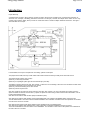
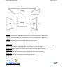
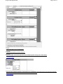
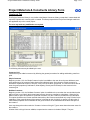
A fundamental concept in EnergyGauge Summit is that it structures the building into a hierarchical collection of
elements. For example, a building (sometimes referred to as Project) consists of multiple Zones which in turn may
contain many Spaces, Walls, Floors, Roofs etc. Walls can further contain multiple Windows and Doors. The figure
demonstrates the concept.
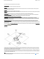
In the illustration, the Project is composed of the building, systems and the plant.
The project has a PLANT, that may include chillers and/or boilers that are served by the utility and/or other fuel sources.
The project has two systems, Sy1 and Sy2
System Sy1 is served by the PLANT
System Sy2 is a packaged system type that is served directly by the utility.
The building consists of three zones: Zo1; Zo2; and Zo3. (A Zone is a unit of a building in which the air is assumed to be well mixed
and where the temperature can be assumed to be uniform)
System Sy1 serves the following Zones: Zo1 and Zo2
System Sy2 serves only Zone Zo3
Zone Zo1 consists of five spaces of various sizes: Sp1; Sp2; Sp3; Sp4; and Sp5. The sum of the areas and volumes of the five
spaces constitute the area and volume of Zo1. (A space is a portion of a Zone having a distinct internal load characteristic, such as
Lighting and Equipment loads)
Zone Zo1 has two exterior walls: Zo1Wa1 (west) and Zo1Wa2 (north).
Zone Zo2 has two exterior walls: Zo2Wa1 (north) and Zo2Wa2 (East), and a partition wall Zo2Wa3 that is next to Zone Zo1.
The east wall Zo2Wa2 in zone Zo2 contains a window Zo2Wa2Wi1. The orientation of windows need not be specified. It is inherited
from the wall on which it is mounted.
Zone Zo3 has three exterior walls namely Zo3Wa1 (west), Zo3Wa2 (south), and Zo3Wa3 (east).
Zone Zo3 has two partition walls: Zo3Wa4 which is next to Zone Zo1 and another Zo3Wa5 that is next to zone Zo2.
The south wall Zo3Wa2 in zone Zo3 contains a door Zo3Wa2Dr1. The orientation of door need not be specified. It is inherited from
the wall on which it is mounted.
EnergyGauge Summit
Page 3 of 10
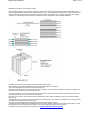
Materials and Constructs - Introductory Concepts
Unlike prior DOS versions of Summit where choices for construct (or envelope types) were mostly limited to prebuilt Wall or Roof
types, EnergyGauge Summit gives the user virtually unlimited choices. First, the software provides the user with an extensive list of
constructs for walls, roofs and floors. Second, the user has the option of creating their own constructs and using them repeatedly.
Therefore an understanding of the basics behind constructs is crucial in being able to use the software effectively.
A building may contain several envelope units such as walls, roofs and floors.
Each envelope unit has associated dimensions (such as width and height) and a construct.
The construct specifies the physical make up of the envelope unit.
More than one envelope unit can have the same construct. Therefore, once a construct is developed or included in a project, it can
be used to specify the make up of several envelope units.
A construct consists of one or more layers that make up the construct, except for a simple construct where layers do not exist and
gross properties of the construct are used in the calculations
Each layer is a slice of the construct that has distinct characteristics that include the material it is made of, thickness and framing
factor (if any).
The aggregate of each property of the layers constitutes the overall property of the construct. For example, the sum of the thickness
of the layers is the total thickness of the construct.
Each layer must be associated with a material that must exist prior to building a construct.
A material has specific detailed thermal properties such as conductivity, density, specific heat and thickness. Alternatively, in lieu of
these properties one can specify only the R-Value in which case the material is assumed to be mass less.
For details on how to build constructs, see the section on Project Materials and Constructs
EnergyGauge Summit
Page 4 of 10
Project
What is a project?
A project is your building input containing components such as zones, walls etc. When saved, the file has an extension .egc
Create a new project
You can open a project using the 'New' tool button or from the 'File' > 'New' menu.
Open an existing project
You can open a project using the 'Open' tool button or from the 'File' > 'Open' menu.
Templates
What is a template?
A template is a file with preset information that can be used as a starting point for a new project. Templates contain preset project
and resource information such as constructs, materials and fenestrations. Users may create and save as many templates as they
need, and choose any template to create a new Project. Creating new projects from templates can save considerable time,
especially if constructs, materials and fenestrations that are often used are saved in a template for repeated use. In addition, the
user can also set the default fenestrations envelope constructs.
Create a template
From the main menu, Click 'File' > 'New' >'Template'. Make your modifications and save it.
Modify an existing template
Click 'Open'. Then select a template (a file with .EGT extension) from the open dialog. Make your modifications and save it.
Create a new project using Templates
1. A template file must first exist. If not, create one. Or use the sample template provided with the software.
2. Click 'File' > 'New' > 'Project from Template'.
3. Select a template (a file with .EGT extension) from the open dialog.
3. This creates a new project based on the selected template.
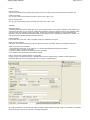
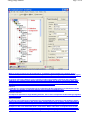
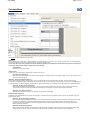
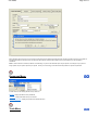
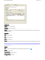
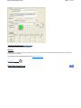
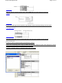
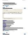
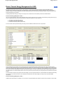
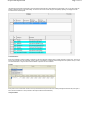
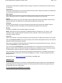
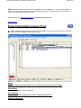
How do I know if I have opened a template or a project file?.
A Project will have a Project Explorer (tree). A template does not have an explorer (tree). In addition, the form layout will be
significantly different for each. See the figure below for an example of a template layout.
To modify Fenestrations in the template click 'Tmpl Fenestrations' button located on the right. Make your modifications. An alternate
access is through the main menu. Click 'Edit' > 'Template Fenestrations'.
EnergyGauge Summit
Page 5 of 10
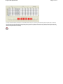
To modify Materials and Constructs in the template click 'Tmpl Materials and Constructs' button located on the right. Make your
modifications. See the section onMaterials and Constructs Library for editing functions. An alternate access is through the
main menu. Click 'Edit' > 'Template Materials and Constructs'.
To set or modify preferences, in the main menu click 'Edit' > 'Template Preferences'. and make your modifications.
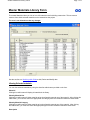
Master Library
What is the Master Library?
The Master Library contains extensive resources on materials, fenestration and constructs. It serves as a repository from which you
can draw into your individual project or template. Users cannot change information contained in the master library.
Accessing the Master Library
From the main menu, click 'Resources' --> 'Master Library' . Then click the library component you want to open.
Note: The Master Library can be accessed even if a project is not open.
Project Library:
What is a Project Library?
The project library is similar to the master library but unlike the Master Library is associated with a specific project and provides
resources for the project. Each project has its own project library. Project Libraries may be edited.
Accessing the Project Library
First, a project must be open. You can access the Project Library by selecting the "Prj Resources" tab of the project explorer and
then clicking the library button you want access. Alternatively, you can access it from the main menu. To do this from the main menu
click 'Edit' . Then click the project library component you want to open.
Note: The project library can be accessed only if a project is open.
Miscellaneous:
Some fields may be inactive, why?
Some fields are intentionally kept inactive or not editable. They usually represent the defaults used in calculations and are not usereditable.
What are tool tips? How do I get tool tips displayed?
In general, if you hover the mouse on any (non grid) field on any form, a tool tip appears giving more information about that field,
such as data ranges and units.
What are the units of the various data?
Units are not written on the forms. Use the tool tip feature above to check input units.
Important note:
You must tab out of the field you are editing (or move to another field and click the mouse) before the change will take effect.
If you switch screens or choose to calculate or save without first moving to another field, the change will not be saved or included in
the calculation.
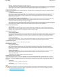
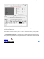
Getting Started
General Layout:
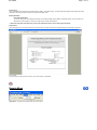
Upon starting EnergyGauge Summit, the following window comes up.
EnergyGauge Summit
To create a new project click the 'New' tool button.
To open and work on an existing project, click the 'Open' tool button.
You can also open an existing or new project from the 'File' menu.
If you require help, click on the 'Help Contents' button or use the 'Help' from the main menu.
Project Explorer
Page 6 of 10
EnergyGauge Summit
Page 7 of 10
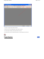
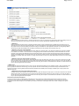
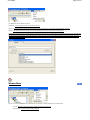
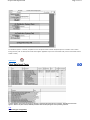
When a project is opened, the Project Explorer (sometimes called building tree) appears. It is a
hierarchical representation of the entire building. It is through the Project Explorer that one navigates
the various building components. It is also used to add and delete various building components.
In general, the Project Explorer (tree) consists of nodes representing Collections and Components.
Collections are containers that appear in bold face and contain one or more components under them.
Example: the 'Zones' Collection contains one or more individual zones. A component represents a
physical element of a building such as a wall, door, or window etc.
Collections
A collection is a group of a particular type of component. All the components in a collection are of the
same type. For example, a collection of Zones only consists of individual zones.
Individual Components
A component represents a single building element. One or more components of the same type together
form a collection.
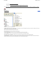
Adding a component
To add any new component of a particular type first highlight the collection by left-clicking it. Rightclick on the selected collection and use the 'add' option from the pops-up menu. A new component of
that type will be added and the input data form will appear (usually) on the right side of the screen.
Example: to add a new wall under Zone 1, first select 'Walls' under Zone 1. Keep the cursor on the
'Walls' and right click. Select the 'Add New' option from the pop-up menu to add a new wall. The data
input form for the wall will show up on the right. You may now input your data for the new wall.
EnergyGauge Summit
Page 8 of 10
Selecting a component to edit
Just clicking on an individual component opens the data input form for that component, For example,
clicking on the component labeled 'Zone 1' opens the data input form for Zone 1.
Deleting a component
Select (left-click) an individual component node. Right-click the component and choose 'Delete' from
the pop-up menu.
Expanding and collapsing the Project Explorer tree
Click on the + or - sign on the tree node to expand or collapse the tree. Right-clicking on a selected
node opens a pop-up menu with options to expand or collapse the tree.
Exceptions
'Plant', 'Water Heating', 'External Lighting' and 'Piping' are Collections whose components are placed on a form
grid in a table format. As an example, click 'Water heating'. An input data form containing a grid with
all water heaters in the project will appear.
Copying and Pasting
You can copy any component of a building, such as a Zone or Wall and paste it into the corresponding
collection. For example a 'Wall' can be copied and then pasted into any 'Walls' collection.
Steps to Copy and Paste
1) Select (using the mouse) the component that is to be copied
2) Right-click on the selected component. A pop-up menu appears.
3) Select the copy option in the pop-up menu. (The component is now placed in a Copy buffer indicated
by the label at the bottom of the Project Explorer)
4) Select (using the mouse) the corresponding Collection where you would like to paste the copied
component. For example, if you copied a Wall, select any 'Walls' collection.
5) Right-click on the selected collection. A pop-up menu appears.
6) Select the 'Paste' option in the pop-up menu. The component will be copied into the selected
collection.
Working with Grids
Working with grids (or Data Tables) - General Procedures
Grids (or data tables) are extensively used in EnergyGauge Summit 2004. These spreadsheet like grids
can display large amounts of data in a concise fashion in addition to providing the ability to edit
displayed data. They appear on several forms, such as Project and Master Libraries, 'Water Heating',
'External Lighting', 'Piping', 'Space', etc. A clear understanding of how to work with Grids is critical in
effectively using the software. The general actions that the user is likely to perform with grid are
described in this section.
EnergyGauge Summit
Page 9 of 10
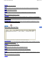
A typical data grid
Add rows to grids
There are generally two ways to add rows to grids.
1) Select the grid (just click anywhere on the grid) using the mouse and then press the 'Insert' key on
the keyboard. Follow the instructions that appear.
2) Right-click the mouse over the grid and then select the ‘Add’ option from the Pop up menu. Follow
the instructions that appear.
Delete a rows on a grid
There are generally two ways to delete rows from a grids.
1) Select any cell on the row you want to delete using the mouse and then press the 'Delete' key on the
keyboard. Follow the instructions that appear.
2) Right-click on the cell in the row you want to delete on the grid and then select ‘Delete’ from the Pop
up menu. Follow the instructions that appear.
Move between cells on a grid
Use the mouse to click on a cell. Also, you can use the Tab key to move from cell to cell.
Edit individual grid cells
There are several types of grid cells.
Cells with numeric or text data
These are cells where numeric or text data can be entered. Double-clicking the cell puts it in edit
mode. Pressing the F2 key also has the same effect. You can then enter the new value. To complete
the edit, press the 'Enter' key on the keyboard or click elsewhere on the grid. If the cell is already
active (as shown by a light focus rectangle), just begin typing the new value to edit the cell.
Cells where
appears when selected
These cells usually require data from other dialogs. Click on the
Cells where
appears when selected
These cells require selection from the drop down. Click on the
button and follow the instructions that appear.
button and make your selection.
Cells where appears when selected
Values in these cells can be changed up or down. Click on the up or down arrow depending on what you want to do.
Cells where or appear
These specify an unselected or selected option. Values in these cells can be toggled by clicking on the
cell, or pressing your 'Space-Bar' key on your key board.
Note: Some grid cells may not allow any of the above. It is usually because the cells are temporarily or
permanently non-editable.
Sorting Grids
EnergyGauge Summit
Page 10 of 10
Most grids can be sorted by clicking the column header. To sort a single column, click on that column
header. Clicking a header on an already sorted column reverses the sort order and resorts. You can sort
multiple columns (up to three) by holding down the 'CTRL' key and clicking up to three column headers
one after another (while keeping then 'CTRL' key down).
Manually or automatically (Auto size) resize Grid Columns widths
In general, double clicking on a column header will auto size the column width to the largest entry in
that column. To auto size all columns, double click the top left corner label that is common to both the
column headers and row labels. You can manually resize column widths by moving your mouse
between column headers until a resize cursor appears. Hold the left mouse down and move left or
right.
Manually resize Grid Row heights
You can manually resize row height by moving the mouse between row labels until a resize cursor
appears. Hold the left mouse down and move up or down.
Steps to Comply with Florida 2010 Building Code
FLORIDA ENERGY CODE COMPLIANCE FOR COMMERCIAL BUILDINGS
Compliance options
The three compliance procedures for the FLORIDA ENERGY CODE COMPLIANCE FOR COMMERCIAL BUILDINGS are:
1. Total Building Performance Compliance
2. Prescriptive Envelope Compliance for Shell Buildings
3. Prescriptive Compliance for Renovations, Occupancy Change, etc.
4.
These can be invoked by going to the appropriate items in the calculate menu as follows:
Calculate -> 2010 Florida Code Compliance -> Total Building Performance Compliance or other options
Steps for compliance:
1. Open new file and enter data. The main user manual explains all the screens, input procedures and input
details.
2. After entering inputs go to Calculate -> Error Check. Correct errors that are found
3. Run the appropriate compliance Calculate -> 2010 Florida Code Compliance -> Total Building Performance
Compliance or other options
4. Check the reports generated to see if the building complies. See section on Appendix A on input and output
reports.
5. Print the reports and look for elements that have failed. The reasons for failing will be given in the reports
6. Make changes to inputs that have failed and re run the calculations until you are able to comply.
File Menu
Page 1 of 11
File Menu
The File menu consists of the following sub menus:
New - It consists of 3 sub menus.
Project(FL Code): Opens a new project for code compliance.
Project From Template (FL Code): Opens a new project for code compliance from a template. When this option is chosen, a dialog appears for
selecting the template the new project is to be based on.
Template: Creates a new Template.
Open - Opens a file. Either a project (.EGC) file or a template (.EGT) file can be opened for data input.
Close - Closes the current file.
Save - Saves the changes made to the current file on to the hard disk.
Save as - Saves the current file under a new user specified filename.
Print - Prints the input data of a currently open project.
Exit - Closes the application.
Edit Menu
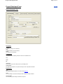
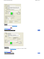
The 'Edit' menu has the following sub menus:
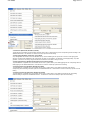
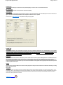
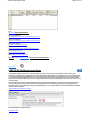
Project Preferences - This sub menu opens the dialog for settings defaults for the current project or template as shown below:
File Menu
Page 2 of 11
You can set the default type for each envelope component. Any new envelope component you add to the project will use these settings. You can change
these setting at any time.
Project Materials and Constructs - This sub menu opens the Project Materials and Constructs Library for editing.
Project Fenestration - This sub menu open the Project Fenestration Library for editing.
Project Data - This sub menu opens the Project Data Input Form for editing.
Enter LEED 2.2NC Additional Inputs - This sub menu opens the LEED NC22 Additional Inputs Form for editing.
Project Profiles & Schedules - This sub menu opens the Project Profiles & Schedules menu for editing.
View Menu
The 'View' menu contains the following sub menus:
Project Explorer - shows or hides the Project Explorer as applicable.
Status Bar - displays an informational status bar at the bottom when checked.
DOE Outputs - sas the following sub menus:
* Last Design Run
* Last Run
The calculation engine, DOE-2.1E, produces text outputs that can be viewed for possible errors, warnings and cautions. The above two sub menus are
provided only to be used for debugging should the need arise.
File Menu
Page 3 of 11
Calculate Menu
The Calculate menu has the following sub menus:
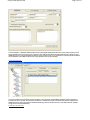
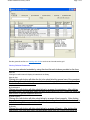
Error Check
Displays the data errors in the project. It usually consists of the component being error-checked, an error message, possible cause, and possible resolution.
It is recommended that an error check be performed before a compliance calculation is run.
You can also check for errors by clicking the red 'Check' label at the bottom of the Project Explorer. Nodes with errors appear in red. Hovering the
mouse on the node with error displays a tool tip with the error message.
* Whole Building
Checks errors for the whole building.
* Envelope Only
Checks errors only for the building envelope namely the walls, floors and roof.
2004 Florida Code Compliance
Compliance reports will be displayed on the screen when Calculate -> Compliance and one of the following options is chosen. The Compliance sub
menu has the following options:
* Method A - Energy Cost Budget Compliance
Runs the Method A (whole building) code calculation. This is a computer based annual energy performance calculation. Under this method energy
performance is calculated for the entire building based on the envelope and major energy-consuming systems specified in the design, and simultaneously for
a reference building of the same configuration but with reference features. Note that this runs and displays only the Whole Building Compliance Calculation.
* Method B - Envelope Trade-Off Compliance
Runs the Method B (component) code calculation. This is a computer based calculation. Under this method, each component of the building
systems must meet minimum performance standards. Note that this runs and displays only the Envelope Compliance Calculation.
* Method C - Prescriptive Compliance
Runs Method C which checks for line by line compliance of each element in the building.
2008 Florida Code Compliance
Compliance reports will be displayed on the screen when Calculate -> Compliance and one of the following options is chosen. The Compliance sub menu
has the following options:
* Method A - Energy Cost Budget Compliance
Runs the Method A (whole building) code calculation. This is a computer based annual energy performance calculation. Under this method, energy
performance is calculated for the entire building based on the envelope and major energy-consuming systems specified in the design, and
simultaneously for a reference building of the same configuration but with reference features. Note that this runs and displays only the Whole
Building Compliance Calculation.
* Method B -Shell Building Compliance
Runs the Method B code calculation for shell buildings. Under this method, the building envelope must meet minimum prescriptive criteria. If the
building is unable to meet any of the prescriptive criteria under this method, the building can be brought under code using Method A.
File Menu
Page 4 of 11
* Method B - Compliance for Renovations, Occupancy Change, etc.
Runs Method B code calculation for buildings that undergo renovations, occupancy changes etc. Under this method, each component of the building
systems must meet minimum prescriptive standards. Only those building components that are being renovated should be entered. If the building is
unable to meet any of the prescriptive criteria under this method, the building can be brought under code using Method A.
2010 Florida Code Compliance
Compliance reports will be displayed on the screen when Calculate -> Compliance and one of the following options is chosen. The Compliance sub menu
has the following options:
* Total Building Performance Compliance
Runs the Method A (whole building) code calculation. This is a computer based annual energy performance calculation. Under this method, energy
performance is calculated for the entire building based on the envelope and major energy-consuming systems specified in the design, and
simultaneously for a reference building of the same configuration but with reference features. Note that this runs and displays only the Whole
Building Compliance Calculation.
* Prescriptive Envelope Compliance for Shell Buildings
Runs the Method B code calculation for shell buildings. Under this method, the building envelope must meet minimum prescriptive criteria. If the
building is unable to meet any of the prescriptive criteria under this method, the building can be brought under code using Method A.
* Prescriptive Compliance for Renovations, Occupancy Change, etc.
Runs Method B code calculation for buildings that undergo renovations, occupancy changes etc. Under this method, each component of the building
systems must meet minimum prescriptive standards. Only those building components that are being renovated should be entered. If the building is
unable to meet any of the prescriptive criteria under this method, the building can be brought under code using Method A.
Florida Commercial Building Rating
* 2004 FL Rating
Runs a simulation that compares the total energy use of the design building under consideration, with the reference building created using the
ASHRAE 90.1 (2004, Appendix G) standard. The rating report gives an index called the EPI (Energy Performance Index) that indicates how much
the building under consideration costs to run as compared to the baseline reference building.
2001 ASHRAE 90.1 Compliance
* Energy Cost Budget Method
Runs the whole building code calculation. This is a computer based annual energy performance calculation. Under this method, energy performance
is calculated for the entire building based on the envelope and major energy-consuming systems specified in the design and simultaneously for a
reference building of the same configuration, but with reference features. Note that this runs and displays only the Whole building compliance
calculation.
* Envelope Trade-Off Option
Runs the component code calculation. This is a computer based calculation methodology. Under this method, each component of the building
systems must meet minimum performance standards. Note that this runs and displays only the Envelope compliance calculation.
* Prescriptive Building Option
This option checks for line by line compliance of each element in the building.
2004 ASHRAE 90.1 Compliance
* Energy Cost Budget Method
Runs the whole building code calculation. This is a computer based annual energy performance calculation. Under this method, energy
performance is calculated for the entire building based on the envelope and major energy-consuming systems specified in the design and
simultaneously for a reference building of the same configuration, but with reference features. Note that this runs and displays only the Whole
building compliance calculation.
* Envelope Trade-Off Option
Runs the component code calculation. This is a computer based calculation methodology. Under this method, each component of the building
systems must meet minimum performance standards. Note that this runs and displays only the Envelope compliance calculation.
* Prescriptive Building Option
This option checks for line by line compliance of each element in the building.
ASHRAE (Appendix G) Performance Rating
This specifies a performance rating method and is a modification of the Energy Cost Budget Method specified in ASHRAE Standard 90.1. It is used for
buildings that substantially exceed the requirements in Standard 90.1 but is not meant as an alternative to the Energy Cost Budget requirements stated in
Standard 90.1. It is useful for evaluating all proposed designs, including alterations and additions to existing buildings, except designs with no mechanical
systems.
* Version 2001
Runs an Appendix G rating for ASHRAE Standard 90.1 2001
* Version 2004
Runs an Appendix G rating for ASHRAE Standard 90.1 2004
LEED
LEED represents The Leadership in Energy and Environmental Design (LEED) a US Green Building Council (USGBC) Rating System, the nationally
accepted benchmark for the design, construction and operation of high performance green buildings. This menu option runs the following simulations.
Detailed instructions for LEED online submittal
File Menu
Page 5 of 11
* LEED NC 2.1
Runs the LEED New Construction (NC) 2.1 simulation that reports the number of credit points in the LEED rating system that a building can earn for
improved energy performance. This menu item should be used only for projects registered with USGBC before January 1, 2006.
* LEED NC 2.2
Runs the LEED New Construction (NC) 2.2 simulation that documents the number of LEED EA Credit 1 USGBC points for building energy use
optimization that can be earned for the proposed building. The points are awarded on the percentage difference between the annual energy use of
the proposed versus the reference building constructed according to the ASHRAE 90.1 2004 Appendix G standards. The EnergyGauge software
automatically calculates these USGBC points and displays a detailed report of the proposed versus reference energy use.
* LEED NC 2.2 - EA Credit 1 Online Submittal
This menu option is specific to users wishing to submit their LEED NC 2.2 simulation data, in the official PDF template format required by USGBC,
to the USGBC online website for LEED certification. The EnergyGauge Summit software will automatically create this LEED PDF form from user
input taken via the LEED 22 NC Additional Inputs form and simulation results. The user can then submit this PDF form through the EnergyGauge
interface to the USGBC website. Any changes made by the user directly in the PDF file shown in the EnergyGauge interface will not be saved or
submitted to the USGBC LEED online website. Any changes required should be made from the LEED 22 NC Additional Inputs form and the building
input data.
* LEED NC 2.2 - EA Credit 1 Report (Adobe not required)
Does the same calculation as the EA Credit 1 Online Submittal menu option but displays the output report in a format that is required for the LEED
NC 2.2 EA Credit 1 PDF. This option does not require Adobe Acrobat Professional to be installed on the client computer. The user has the ability to
print this report as a 'Microsoft XPS Document Writer' document and copy all the outputs in to the LEED PDF for submittal. The 'XPS' document can
only be opened using Microsoft Internet Explorer.
* LEED NC 2009
This menu option will calculate the LEED EA Credit 1 points as per the LEED NC 2009 guidelines from the USGBC. EA Credit 1 points are awarded on the
percentage difference between the annual energy use of the proposed versus the reference building constructed according to the ASHRAE 90.1 2007
Appendix G standards. The EnergyGauge software automatically calculates these USGBC points and displays a detailed report of the proposed versus
reference energy use.
* LEED NC 2009 - EA Credit 1 Report (Adobe not required)
This option does the same calculation as the LEED NC 2009 menu option but displays the output report in a format that is required for the LEED NC
2009 EA Credit 1 PDF. This option does not require Adobe Acrobat Professional to be installed on the client computer. The user has the ability to
print this report as a 'Microsoft XPS Document Writer' document and copy all the outputs in to the LEED PDF for submittal. The 'XPS' document can
only be opened using Microsoft Internet Explorer.
2005 Commercial Federal Tax Deduction
Provisions in the Energy Policy Act 2005 allow for a tax deduction for energy efficient commercial buildings that reduce annual energy and power
consumption by 50% compared to the ASHRAE 2001 Standard 90.1. A special approval code must be provided to use this feature. Once this code is
specified by the user under the Help menu, and verified by the software, it need not be entered again till the license is valid. Following are the options
available.
File Menu
Page 6 of 11
* Full Deduction (IRS 2006-52, IRS 2008-40, $1.80/SF)
The full deduction is applicable if the whole building calculation shows a 50% or greater efficiency than the corresponding reference building for the
ASHRAE Standard 90.1. This deduction is a maximum of $1.80 per square foot of the building.
* Partial Lighting (IRS 2008-40, Interim Rule, up to $0.60/SF)
As per IRS guidelines documented in the notice IRS 2008-40, any commercial building with an improvement of over 25% in the lighting power
density as compared to the ASHRAE 90.1 2001 requirements can qualify for a tax deduction. The deduction is scaled appropriately, as per IRS
guidelines, in the 25% to 40% savings range and a deduction of $0.60 /SF can be taken for savings over 40%.
* Partial Lighting Deduction (IRS 2006-52, IRS 2008-40, Permanent Rule, $0.60/SF)
The partial deduction is applicable if the code calculation shows a 50% or greater efficiency of the building lighting than the corresponding reference
building lighting for the ASHRAE Standard 90.1. This deduction is a maximum of $0.60 per square foot of the building.
* Partial System Deduction (IRS 2006-52, IRS 2008-40, $0.60/SF)
The partial deduction is applicable if the code calculation shows a 50% or greater efficiency of the building mechanical system than the
corresponding reference building mechanical system for the ASHRAE Standard 90.1. This deduction is a maximum of $0.60 per square foot of the
building.
* Partial Envelope Deduction (IRS 2006-52, IRS 2008-40, $0.60/SF)
The partial deduction is applicable if the code calculation shows a 50% or greater efficiency of the building envelope than the corresponding
reference building envelope for the ASHRAE Standard 90.1. This deduction is a maximum of $0.60 per square foot of the building.
File Menu
Page 7 of 11
System Sizing
This is a beta feature that will size the user building using the DOE 2.1E simulation engine. The output report will provide the sized heating and cooling
capacities for all system and plant components included in the building model.
Building Simulation
* Run DOE2.1E Simulation
This runs an energy (not code compliance) calculation on the design building using the DOE-2.1E simulation engine. It is not an option nor a
requirement for code compliance. However, its output may be of useful to the designer.
** Some of the 'Calculate' menu options may or may not be visible based on the version of the program purchased
Report Viewer
After a calculation is run your report will show up in the report viewer. Use the arrow buttons to navigate through the various pages in the report.
Export to PDF
Use the "Export to PDF" button to save a copy of the report in pdf format.
Reports Menu
Input Report - This produces a detailed report of the project inputs.
File Menu
Page 8 of 11
Before displaying the input report, the user is asked to select whether the Profiles & Schedules information should be included in the report. The Profiles &
Schedules information is voluminous and is not required to be included for Florida Code Compliance but may be mandatory for other compliance
calculations.
Note: In certain instances of renovation, addition or shell buildings, only some of the individual reports may be required. For example, if only a system is
being replaced, only the system report may be required. Check your current energy code manual and local jurisdiction for specific requirements.
Resources Menu
Provides access to the following Master Library resources:
Materials - Displays the Master Library of Materials
Constructs - Displays the Master Library of Constructs
Profiles and Schedules - Displays the profiles and schedule data forms
Tools Menu
File Menu
Page 9 of 11
The Tools menu has the following sub menus:
Customize - This menu allows the user to customize the Tool bars.
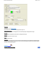
Options - This option allows the user to change the application user interface layout. Layout options include Tab location and style.
Settings - This allows the user to set, change or remove the default directory from which input files are initially opened.
Another option in the setting menu is for the feedback control when for users when entering building data. This feedback control when set to a particular form
of calculation, for example should the user be running an ASHRAE 90.1-2001simulation, the feedback dropdown menu should be set to ASHRAE 90.1-2001,
thus allowing a user to see whether individual data fields fail or pass according to the rules of the feedback standard selected, when entering data in the
forms. This setting is shown below:
Window Menu
The sub menus under the Window menu provide the user with the option of viewing multiple forms in several formats.
Cascade - Reduces the size of open window and places them on top of each other
Tile Horizontal - All open windows are tiled horizontally.
File Menu
Page 10 of 11
Tile Vertical - All open windows are tiled vertically.
Arrange Icons - The window icons are minimized and are arranged at the bottom of the screen.
Note: These menus are only for the visual convenience of the user. Window in this context does not refer to the 'Windows' or 'fenestrations'. in a building.
Help Menu
Sub Menus provides access to the Help system.
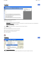
Contents - This sub menu opens the contents dialog of the Help system. The user can navigate to any topic from the contents. In addition the user can print
any topic displayed or book from the contents dialog.
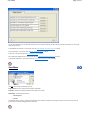
Index - Opens the searchable Index dialog of the help system.
Search For Help On - Opens a key word search of the help system.
Technical Support Website - Directs the user to the EnergyGauge Summit technical support website.
Check For Updates - Allows the user to automatically check for latest updates to the EnergyGauge software.
Set Approval Code for Tax Deduction - Allows the user to start using the tax deductions feature of the EnergyGauge software.
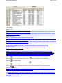
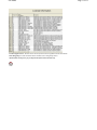
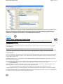
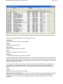
License Information - Provides the user with a table that lists all the features offered with the EnergyGauge Summit software and provides information on
features for which license has been procured for that particular copy. The license table looks as follows:
File Menu
Purchase Upgrade License - Allows the user to select and purchase online an upgraded license with extra features.
About EnergyGauge - Provides information about the installed version of EnergyGauge Summit.
Important Note: Pressing F1 key on your keyboard will provide context sensitive help.
Page 11 of 11
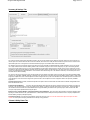
Project Data Input Form
Project Data Input Form
Project Information Tab
Description
Acronym
A short description (up to 20 characters).
Title
A fuller description (up to 50 characters).
Owner
The building owner information.
Location Info
Address
The address where the building is located. Two lines are available for this.
City
State
Zip
Jurisdiction
The city and/or county with authority to issue your building permit.
Climate Option
For Florida code compliance, this option must always be set to "By Florida Jurisdiction".
Building Info
Type
The building classification based on use class from the Type list.
Class
The class building such as New or existing for which compliance is being calculated.
Area from Plans
The total building square footage as indicated on the plans.
Page 1 of 33
Project Data Input Form
Page 2 of 33
No of Stories
The number of the separate floors in this building project. The default is 1.
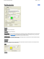
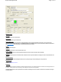
Rotate Building clockwise by (or Azimuth)
The orientation of the building is relative to true north. It is expressed in degrees from 0 to 360. The default is 0.0. Changing this angle has the effect of
rotating the building about its z-axis (vertical axis). The default value is 0 and usually does not require modification. Clicking will open the Azimuth Dial
window. Common values are: North = 0; South = 180; West = 270; East = 90.
There are 3 ways to enter the value
i) Click on the minus
or plus button
to select the value and then click on 'OK'.
ii) Click on the E or W or N or S or NE or NW or SW or SE to enter the selected value and then click 'OK'.
iii) Click on the wheel to select the desired value and then click 'OK'.
NOTE: Orientation of Walls, Roofs and Floors are relative to the building orientation. Any value other than zero for the building orientation
will rotate all Walls, Roofs and Floors correspondingly during calculation.
Select Profile
Use the button to load a profile for the zone. The profile will include all the schedules for internal loads and gains in the building. For non-code purposes,
the profiles and schedules can be entered and modified by the user. All code related simulations will use default values for profiles and building internal
loads and gains schedules.
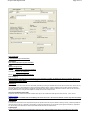
Designer Tab
Project Data Input Form
Enter names of individuals and Registration as applicable. (up to 50 characters)
Zone-Sys Assignment Tab
For Method A Compliance all zones in the project must be assigned to systems by checking the appropriate box.
A system can have more than one zone assigned to it. However, multiple systems cannot be assigned to a single zone.
Page 3 of 33
Project Data Input Form
Page 4 of 33
Summary & Settings Tab
The summary window presents all the information entered by the user for the particular project. Below the summary window are a few check-box and
text box inputs. The 'Override Internal Loads' check box if selected, allows the user to modify the internal loads in the space from the 'Loads' tab on the
'Space Data Input Form'. Leaving this box unchecked will allow the program to use default values for the internal loads.
The 'Draft Run' check box is especially useful in saving time when running the LEED or ASHRAE Appendix G 2004 simulations. The user can quickly
run a single orientation for the reference building instead of all 4 orientations to figure out how much of savings they can get for the annual proposed
energy use over the reference energy use. Once the acceptable level of percentage savings has been reached, this box can be unchecked to run all 4
orientations to get the final results. Reports generated when the 'Draft Run' option is checked will have a note saying that it was a draft run and a full run
needs to be completed for final report submission. Users should be aware that the single run in the 'Draft Run' mode may not necessarily be the worst
orientation for the reference building.
The ‘Use one unit per zone’ check box can be checked to help reduce the heating and cooling unmet hours if they are too high for the baseline building
model for non-code (LEED, ASHRAE Appendix G) simulation runs. When the box is checked, and the proposed building model contains a single system
assigned to multiple zones, each of those multiple zones will be assigned their own system in the baseline model. This will help reduce the unmet hours
for the baseline run in the case where a single zone system is forced to serve multiple zones due to equipment selection as required by ASHRAE
Appendix G.
Override Internal Loads: If checked, internal loads specified in the Space and Zone Table will be used rather than the defaults. Not applicable for the
2004 and 2008 Florida codes.
Auto Size Proposed Building:
If checked, the proposed building will be internally auto-sized so that the unmet hours for heating and cooling are
minimized. This should be used only when user-entered system capacity is unable to meet loads within bounds of unmet hours. This would happen if
the schedules and internal loads are not well established for the proposed building and therefore the system capacity is unable to meet loads. First
check your input system capacities before using this option.
Baseline Cooling, Capacity Multiplier, and 'Baseline Heating Capacity Multiplier: If the unmet hours for the baseline (or reference building) needs
adjusting to meet the unmet hour rule, (see ASHRAE 90.1 or 2010 Florida Code for details) these three parameters serve as capacity multiplier for the
baseline building to adjust system/plant capacity.
Override Unmet Hours: If checked, this will completely override the unmet hour rule. Do not use this until all other options and inputs have been
verified. Use of this option will require justification to the authority having jurisdiction.
Climate & Utility Rates Tab
Project Data Input Form
Page 5 of 33
Allows the user to choose the climate location for the design building and to enter local utility rates for fuel charges.
TMY3 (Typical Metrological Year) weather data files are now used by default for all code simulation runs in EnergyGauge Summit. For all non-code
simulation runs (LEED, ASHRAE Appendix G etc.), the user has the option to use the older TMY2 weather data set. TMY3 weather data sets are derived
from more accurate and more recent weather data and are recommended to be used for greater simulation accuracy. These data sets are now available
for over 1000 locations in the United States.
To use time-of-use- rates, first check the “Use TOU Schedule?” column. Clicking the button on the “TOU Schedule” column will lead
the user to the TOU schedule used. The user may choose to use another TOU schedule or create one under the main menu Edit ->
Profiles and Schedules, and then invoke the newly created schedule here. Note that TOU schedules are applicable only for electric
rates and not for other fuels.
If checked, this entry tells the program to use user entered utility rates and time of
use rates instead of internal default rates for the 2010 Florida code compliance. This entry has no effect on 2008 and 2004 Florida
code compliance and ratings. For other calculations always the user entered rates are used.
Related Topics
Zone Data Input Form
Project Data Input Form
Page 6 of 33
Zone Load Data
Acronym
A short description (up to 20 characters).
Description
Enter a detailed description (up to 50 characters).
Type
Specifies the type of zone:
Conditioned - maintains zone air at desired conditions.
Unconditioned - Zone is not conditioned.
Plenum - Zones that act as conduits for return air.
Zone Category
Select the category of the zone from a pre-defined list. This is required as for example, the building type may be an assembly, but may have a
zone that serves as an office located in it. The building type selected on the project form will then be an assembly, but the category selected
for this zone will be of type 'Office'.
Dimensions
NOTE: The area and volume of the zone are automatically calculated by summing the individual values for the spaces under the zone. This occurs any
time a change is made to space dimensions or spaces are added or deleted. There is, however, a limitation on the per Zone Area and Volume thus
calculated. Maximum Zone area is limited to 100,000 SF and maximum Zone Volume is limited to 1,000,000 CF. However, these can be overcome by
defining additional Zones or using the Zone Multiplier for multiple zones that are exactly the same.
Area not included in spaces [SF]
Represents extraneous area that has not been included under spaces. This is added to the total space area under the zone. If none, set to 0.
Number of Zones
Specifies the number of identical zones in the building to the current one. If two or more zones are identical, use this entry rather that creating
additional zones.
Thermostat
The thermostat will control the zone to the particular set-point as specified in the zone set point schedule for heating or cooling. It will be responsible for
turning the HVAC system on or off based on zone heating or cooling load requirements. The user should input the type of thermostat (eg. proportional
etc.) and the range or the dead band in which the thermostat should control the zone temperature to.
Lighting Type
Specifies the predominant type of overhead lighting used in the zone. Note that lighting power and type is specified in the space forms.
Project Data Input Form
Page 7 of 33
Source
Specifies internal source type due to sources other than people, lights, or equipment. Note that the source rates rate is specified in the space
forms.
HOW TO HANDLE A PRE-EXISTING UNCONDITIONED ZONE THAT IS NOT PART OF YOUR DESIGN BUT HAS YOUR ENVELOPE NEXT TO IT
In some instances, you may have to account for a zone that pre-exists and is not part of your design. Since the calculation requires a
physical zone whenever an adjacent envelope is specified next to it, the following procedure suggests how to accomplish it with minimal
input and effort.
Steps to account for an Zone that pre-exists.
1) Add a Zone. You may choose to label it as 'PRE-EXIST'.
2) Set the Zone to 'Unconditioned'.
3) Add a Space under this new Zone.
4) Set Space category to 'Unlisted'.
5) Set the width and height of the space equal to the width and height, respectively, of your adjacent wall.
6) Set the depth of the space to a minimum value, say 1 ft.
7) Set No. of Task locations to zero.
8) Add a lighting to the space. Use minimum Watts (equal to what is indicated by the Budget, or say 5 Watts).
9) Set Control Type to 'Security Lighting'.
10) Set No. of Controls to Zero.
11) You can now set your adjacent wall next to this new 'PRE-EXIST' zone.
12) If you are running Method A, you will have to assign the 'PRE-EXIST' zone to some system in the project. As long the PRE-EXIST zone is
set to 'Unconditioned', there will be no energy impact.
Project Data Input Form
Page 8 of 33
Zone Summary
Assigned Supply Air
Total quantity of supply air assigned to the zone from the system.
Outside Air
The total outside air supplied to the zone. This will be calculated either based on ASHRAE 62.1 if defaulted, or can be supplied by the user for non-code
(LEED, ASHRAE Appendix G) simulation runs.
Related Topics
Space Data Input Form
Project Data Input Form
Page 9 of 33
Lighting Tab
Acronym
A short description (up to 20 characters).
Description
A detailed description (up to 50 characters).
Category
Select a space type from the list. For space type not listed select the one most representative from the list. This is a key selection that will
affect the lighting allowance.
Dimensions
Width
Specify the space width in feet.
Depth
Specify the space depth in feet.
Height
Specify the space height in feet.
Multiplier
Used to specify the number of identical spaces. Use this input for spaces that are exactly the same, instead of adding a new space under the
zone.
NOTE: The area and volume of the zone to which the space belongs are automatically calculated by summing the individual values
for all spaces under the zone. This occurs any time a change is made to space dimensions or spaces are added or deleted. Maximum
Zone area is limited to 100,000 SF and maximum Zone Volume is limited to 1,000,000 CF. Space dimensions specified here should
conform to this limitation.
Lighting
Type
This field describes the various lighting types. They are available in the drop down box. Click here for details.
Category
Classified the use of the lighting.
No. of Luminaires
Specify the number of light fittings in that space.
Watts per Luminaire
Specify the lighting wattage per fitting.
Project Data Input Form
Page 10 of 33
Control type
This field describes the type of control used for the particular lighting. A value of "None" is not allowed for this field.
No. of Controls
This field shows the number of control points for the particular lighting.
Area Lighted
For a few categories of the lighting type (for example: category 22 - Specific Retail Display), this extra field requires the user to enter the area
lighted. This field is automatically unlocked for the categories for which this values is required.
See the section on Working With Grids to Add, Delete and Modify the Lighting data.
Loads Tab
For code calculations, the Loads tab on the Space form is provided for information only. Default values are set by the
program based on the space type selected. All inputs on the space loads form will be used in case of non-code
simulation (LEED, Federal Tax Deduction Calculations etc.) only when the 'Override Internal Loads' box on the
'Summary&Settings' tab is checked.
Equipment
Equipment loads should be entered in either 'W/sq ft' or 'kW'. If both values are entered, they are added together for a combined load in each
space. All the space equipment loads are summed up as the total equipment load on every zone. Equipment load is purely sensible in nature
and contributes to the heating or cooling loads in the zone. The 'Equipment' schedule from the associated Zone Profile will control the
amount of equipment load on the zone for every hour in the annual simulation. The equipment load is typically the thermal (heat load) fraction
of all the plug loads in that space.
Source
The source load is entered in Btu/hr and is the sum of all the plug loads in the space. Source loads do not contribute to the heating or cooling
loads in the space and zone.
Occupants
The maximum number of 'Occupants' in the space should be entered as either a value of 'Number of People' or as a value of 'Area per person' or as a
combination of the two. The people load on the space will be modified as per the 'People' schedule specified in the profile associated with the zone that
contains the space. Occupant load will affect the outside (fresh) air fraction required for the zone during an annual simulation unless a fixed value of
outside air has been specified at the zone level.
Related Topics
Project Data Input Form
Page 11 of 33
Wall Data Input Form
Wall info
Acronym
A short description (up to 20 characters)
Description
A detailed description (up to 50 characters)
Select Construct
Allows selection of the construct (sometimes called wall type or envelope type) for the wall. Clicking this button opens a list of all constructs
in the Project. You can then select a construct for the wall from the list. If a suitable construct is not available in the list, you must first add
(or build) the construct in Project Resources before being able to select that construct for the wall.
ASHRAE Category
Allows the user to select the appropriate ASHRAE category for the building component. This determines the maximum allowable assembly Uvalue for that component in the baseline (reference) building
Dimensions
Shape Type
There are various shape types that can be entered. Note that the required number of dimensions will become active and should be entered
upon selecting a shape type. The various shape types are:
i) Square
ii) Rectangle
Project Data Input Form
Page 12 of 33
iii) Triangle
iv) Semicircle
v) Trapezoid
vi) Rectangle with Semicircle
vii) Rectangle with Triangle
If the shape selected is a Rectangle with Triangle or Trapezoid then the user has to enter 3 dimensions in the dimension boxes.
If the shape selected is a square then the user has to enter 1 dimension.
Project Data Input Form
Page 13 of 33
For rest of the shapes only 2 dimensions have to be specified.
Dimensions [ft]
The required dimensions based on the particular shape selected.
Multiplier
Used to specify the total number of identical wall panels located in the same plane. If two or more walls are identical, use this entry rather
than adding more walls to your project.
Location
The explanation given here applies to Walls, Roofs and Floors.
Exterior - Implies that the surface is exposed to the outside (eg. Exterior Walls, Exterior Roofs, Floor that are raised above grade and exposed
to the outside).
Underground - Implies that the surface is on or below ground (eg. basement walls, on-grade and below grade floors).
Adjacent to another zone - Implies that the surface is adjacent to another previously defined zone (eg. partition walls and ceiling between
Stories). In this, case the zone to which this is adjacent to must be selected using the selection button.
The note below applies ONLY to version 1.21 and below.
Important Note:The Adjacent zone selected here must always be a previously defined zone in the project hierarchy. It cannot be a
succeeding zone in the project hierarchy. So the first zone in the project cannot have adjacent surfaces defined. But the second zone in the
project can have surfaces that is adjacent to the first zone. However it cannot have surfaces defined that are adjacent to a third zone which
comes after this one in the hierarchy.
Beginning Version 1.22, the above restriction does not apply and the user is not required to order the zones as above. The program
automatically attempts to reorder zones as required and issues an error message when circular references in adjacent envelopes are
discovered. A circular reference is one in which, for example, an envelope in Zone A is adjacent to Zone B, and another envelope in Zone B is
adjacent to Zone A.
If the location above is adjacent to another zone, then the name of the adjacent zone must be selected by clicking on the Select Adjacent
Zone button
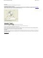
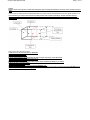
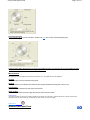
Placement
The figure above gives the general principles of determining the Tilt and Azimuth angles. An outward normal is first drawn from the exterior
side of the surface. An outward normal is a line that is perpendicular to the plane of the surface in question. The tilt angle is the angle made
by the outward normal with the vertical axis as shown in figure.
The azimuth is the direction the surfaces faces. For vertical surfaces, it is the direction the outward normal faces. To obtain the direction for a
non vertical surface, first project the outward normal to the horizontal plane. The direction the projected line faces is the Azimuth, with North
= 0, East = 90, South = 180 and West = 270.
Tilt
Surface tilt. Vertical = 90 (eg. Vertical Wall); Horizontal facing up = 0 (eg. Flat roof); Horizontal facing down = 180 (eg. floor). Click cell to set
value. The following dialog opens:
Project Data Input Form
Page 14 of 33
Orientation (Azimuth)
Surface orientation (North = 0, South = 180, West = 270, East = 90). Click cell to set value. The following dialog opens:
NOTE: Orientation of Walls, Roofs and Floors are relative to the building orientation. Any value other than zero for the building orientation
will rotate all Walls, Roofs and Floors correspondingly during calculation.
Miscellaneous
The following are not user editable and are provided for information only. The defaults are set by the Application.
Gnd Refl
Ground Reflectance is the solar reflectance of the ground.
Infl Coef
Infiltration Coefficient is the infiltration flow coefficient used to compute the infiltration resulting from cracks in a wall.
Outside Emiss
Outside Emissivity is the Emissivity of the exterior side of the wall.
Inside Vis Refl
Inside Visible Reflection is the fraction of light reflected by the interior side of the surface.
Inside Sol Abs
Inside Solar Absorbance is the fraction of radiation absorbed by the interior side of the surface. Radiation may fall on an interior surface through
fenestration placed on other surfaces (eg. Sunshine falling on floors through a window or skylight).
Related Topics
Window Data Input Form
Project Data Input Form
Page 15 of 33
Window Info
Acronym
A short description (up to 20 characters)
Description
A detailed description (up to 50 characters)
Select Glass Type
Select the fenestration type for the window. Clicking this button opens a list of all fenestration in the Project. User can then select a
fenestration for the window from the list. If a suitable fenestration is not available in the list, you must first add (or build) the fenestration to
your Project Resources before being able to select that fenestration for the window.
Usage
Selects window usage type.
SetBack
Distance that the window is recessed into the wall in feet.
Inside Vis Refl
Inside Visible Reflection is the amount of light reflected from the interior side of the window. Not user editable.
Infl Coef
Infiltration Coefficient specifies an infiltration flow coefficient used to compute the infiltration resulting from cracks in the window. Not user
editable.
Internal Shading
Checking the box for Internal Shading will allow the user to specify the type of internal shading from a drop down box.
Dimensions
Similar to Wall Data Input Form.
Shading
Shading (external) for windows is activated by checking the shading check box. A set of data input cells become visible where shading parameters can
be entered. Shading surfaces include Overhangs, Left and Right Fins. Enter all data that is applicable.
The figure shown below is a basic representation of a window and shading as seen from outside. The dimensions are labeled on the figure
and defined below:
Project Data Input Form
Page 16 of 33
Overhang A
Distance from left window edge to left corner of overhang. Units are in feet, 0.0 is the default, and there are no limits.
Overhang B
Distance from top of window to back edge of overhang. Units are in feet, 0.0 is the default, and there are no limits.
Overhang W
Width of overhang. Units are in feet, 0.0 is the default, and the range is 0.0 to no limits.
Overhang D
Depth of overhang. Units are in feet, 0.0 is the default, and the range is 0.0 to no limits.
Overhang Angle
Angle in degrees between overhang and window. When set at 90 degrees, the overhang is perpendicular to the window; if less than 90
degrees, it is tilted downward; if greater than 90 degrees, it is tilted upward. The range is 0 to 180 degrees.
Left/Right Fin A
Distance from left/right window edge to fin back edge. Units are in feet, 0.0 is the default, and there are no limits.
Left/Right Fin B
Distance that top of fin is below top of window. Units are in feet, 0.0 is the default, and there are no limits.
Left/Right Fin H
Height of fin. Units are in feet, 0.0 is the default, and the range is 0.0 to no limits.
Left/Right Fin D
Depth of fin. Units are in feet, 0.0 is the default, and the range is 0.0 to no limits.
Related Topics
Door Data Input Form
Project Data Input Form
Page 17 of 33
Data inputs are very similar to the Wall Data Input Form.
Data on placement and location, etc, are not required.
Shading
Shading for doors is activated by checking the shading check box. A set of data input cells become visible where shading parameters can be entered.
Enter all data that is applicable.
For a detailed account of shading parameters see the Window Data Input Form.
Related Topics
Roof Data Input Form
Project Data Input Form
Roof Info
Data inputs are very similar to the Wall Data Input Form.
Related Topics
Skylight Data Input Form
Skylight info
Data inputs are similar to Window Data Input Form, except shading is not available for skylights.
Related Topics
Floor Data Input Form
Page 18 of 33
Project Data Input Form
Page 19 of 33
Floor Info
Data inputs are very similar to Wall Data Input Form
Some additional inputs associated with underground floor types are:
Underground Floor Type
When the location is chosen as 'Underground', the user should specify the 'Underground Floor Type'.
Slab Type
Specify insulation and geometric characteristics of underground floor type.
Carpeted
Select if the interior floor surface is carpet.
Heated
Select if the slab is heated.
Use F-value
The use F-value check box allows the user to directly enter the perimeter heat loss coefficient for underground floors.
In case the F-value of the floor is not known, the user can choose the slab type and default F-values will be assigned
to the floor construct by the program.
Related Topics
System Data Input Form
Project Data Input Form
Page 20 of 33
Acronym
A short description (up to 20 characters).
Description
A detailed description (up to 50 characters).
No of Units
Enter the number of such units (Use this to input multiple systems serving one or more Zones).
1. Component Name
The type of the component (whether cooling,heating etc) is displayed. If a check box appears near the name of the component,
it indicates that the component is optional and user decided whether to select it or not.
2. Input Parameter
Project Data Input Form
Page 21 of 33
Shows the different required parameters (like capacity,EER, IPLV etc.) for the respective component.
3. Options
Describes the option type for the component. Any sub-option may be selected by clicking on the sub option.
4. Sub Option Parameter
If parameter field appears next to a selected sub option, the value of the parameter must be selected.
Steps for entering the data
To select an optional component click on the check box to select it.
Click on the corresponding column. A pop up window will appear (for example: the figure below displays the selection
of fan control type). Enter or select the value and then click OK.
To choose a particular option in a component click on the radio button.
Project Data Input Form
Page 22 of 33
Air distribution system: If checked, compliance for this component will be checked. Required inputs are "Location" and "R-Value".
Energy Recovery Unit: If checked, ERV credit will be applied. Applicable only for the 2010 Florida Code (see the 2010 Florida code for
details of credit).
Related Topics
Plant Data Input Form
A plant is added or removed from the project by checking or unchecking the appropriate 'Use' check box. Data that must be entered
appears. Based on the plant selected, additional parameters that must be input appears in the parameter grid below.
Type
Shows the type of equipment.
Project Data Input Form
Page 23 of 33
Equipment
Displays the name of the equipment.
Capacity
Specifies the capacity of the selected equipment. The units in which the data is to be entered is also shown.
Quantity
Specifies how many units are installed.
Efficiency
Specifies the efficiency of the equipment. The units in which the data is to be entered is also shown.
IPLV
Specifies Integrated Part Load Value, if required.
Non-Standard?
Applies only to Open Centrifugal Chillers and Hermetic Centrifugal chillers. If checked, the corresponding plant
equipment is considered non-standard and the efficiency requirement for non-standard chillers apply (see ASHRAE
90.1 or 2010 Florida code for details). Non-standard chillers require additional parameters to be input such as Flow/ton
in gpm; LIFT in o F;
Note for Cooling Tower
The cooling tower requires the following input parameters: Performance gpm/hp; Fan type[Propeller or Axial or
Centrifugal]; Tower Type[Open or Closed circuit]
Related Topics
Water Heater Data Input Form
Water Heater Category
This field describes the various Water Heater categories available. They are available in the drop
down box. Select one from the list.
Description
You can type your own description here.
Capacity
The capacity of the water heater. Units are displayed in the cell.
Input Rate
The power rating of the water heater in the appropriate units displayed.
Efficiency
The efficiency of the water heater between 0% and 100%, entered as a decimal (between 0 and 1).
Loss
The loss in the appropriate unit displayed.
Compliance
Project Data Input Form
Page 24 of 33
Shows whether water heater complies with code or not.
Note: Not all inputs may be required for all water heater types.
See the Section on Working with Grids to Add, Delete and Modify data.
Related Topics
External Lighting Data Input Form
External Light Category
External lighting category. Select one from the list.
Description
You can type your own description or comment here.
No. of Luminaires
Specify the number of light fittings in that space.
Watts per Luminaire
Specify the lighting wattage per fitting.
Luminaire Efficiency
Specify the efficiency of each luminaire.
Area or Length
Input depends on the category selected. Enter length or area. Required units will be shown.
Control Type
Specify the type of control for the luminaire from a drop down list.
See the section on Working with Grids to Add, Delete and Modify data.
Related Topics
Piping Data Input Form
Project Data Input Form
Type
Specify the
Page 25 of 33
Piping application.
Operating Temperature
The operating temperature at which the pipe will operate.
Insulation Conductivity
Specify the conductivity of the insulation around the pipe.
Nominal Pipe Diameter
Specifies the diameter of the pipe.
Insulation Thickness
Specify the thickness of the insulation around the pipe.
Check if Runout up to 4 ft
Specific if the pipe is a runout.
Note: Units are shown on the form.
See the section on Working with Grids to Add, Delete and Modify data
Related Topics
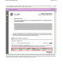
LEED NC22 Additional Inputs Form
The LEED NC22 additional inputs form is only required to be filled up by users planning to run the LEED 2.2 New Construction (NC)
calculation on the proposed (design) building. The results from the LEED 2.2 NC simulation can be submitted, via an existing PDF template,
to the US Green Building Council (USGBC) website for documentation of the EA Credit 1 (EA C1) USGBC points that can be claimed by users
when completing the LEED certification process. The required empty PDF template needs to be downloaded by the user from the USGBC
website prior to running the LEED 2.2 NC simulation. The path for the location of this empty PDF template is to be given in the form as shown
in the figure below.
Once this additional information has been entered by the user for a particular project/building, it will be stored as part of that EGC file. The
remaining information for filling the USGBC simulation data PDF template will be automatically generated by the EnergyGauge Summit
software and pulled into the PDF template every time the LEED simulation is run. The PDF template should be downloaded from the USGBC
website as shown in the figure.
USGBC website PDF Template Download:
The EnergyGauge form is explained below.
General Info Tab:
Project Data Input Form
Page 26 of 33
The menu item Edit --> LEED 22NC Additional Inputs brings up the LEED 22 additional information form. The first tab to be filled out is the
General Information tab. This requires the user, wanting to run the LEED 22 NC simulation and submit their EA Credit 1 data to the online
USGBC web service, to enter the information like their user name, password and so on. This information is required to populate the PDF file
that is submitted to claim USGBC credit points for energy optimization of the proposed building.
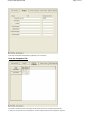
On Site Renewable Tab:
The on-site renewable energy generation and cost information is also required to calculate USGBC credit points and this information is
provided by the user in this form. The information provided here is automatically inserted in the PDF file that should be submitted to the
USGBC web service. Clicking the 'Include On Site Renewable Energy' check-box will allow the user to enter details about the renewable
energy sources in the proposed building.
Exceptional Calculation Tab:
Project Data Input Form
Page 27 of 33
This tab is used to document any exceptional calculation methods that may have been used by the user as defined in the ASHRAE 90.1 2004
Appendix G. The information provided here is automatically inserted in the PDF file that should be submitted to the USGBC web service.
Clicking the 'Include Exceptional Calculation Methods' check-box will allow the user to enter details about the exceptional calculation
methods used in modeling the proposed building as allowed in ASHRAE 90.1 2004 Appendix G.
Related Topics
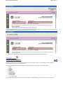
LEED Online Submission Instructions
Please take a minute to review these instructions before running and submitting a LEED calculation using
EnergyGauge Summit v 3.22.
Pre-submittal tasks
EnergyGauge is about to enter all your data in your LEED EA Credit 1 template. Please review all the information on the template
before submission.
NOTE: Do not edit the PDF template displayed by the software as that data is not saved. Display is for review purposes only
If you need to make any changes to the inputs, please close the template and make the changes in the EnergyGauge inputs screens
Post-submittal tasks
Once you have submitted your LEED EA Credit 1 data through the EnergyGauge software, please download your EAc1 PDF template
for that project from the LEEDOnline website. If your submission was successful, this template should now contain all the outputs
from the LEED simulation runs.
Review the template for any incorrect entries and enter all additional entries not handled by EnergyGauge. These include, but are not
limited to:
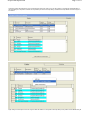
{ External Lighting Data:
Annual external lighting energy use must be added for both proposed and baseline buildings as new entries in tables 1.8.1 and 1.8.2.
This value should generally be the same for both the proposed and baseline buildings unless otherwise justified.
z Water Heating Data:
EnergyGauge does not currently simulate annual energy use for certain water heaters. If an entry for domestic hot water use is
missing from table 1.8.1 and 1.8.2, then such an entry must be added at this point.
z Any other missing data that may be required by the USGBC should be added into the template at this point.
The PDF template should now be re-submitted manually (not through EnergyGauge) for final review of the project by the USGBC.
Any changes/additions made to the template after its submission through the EnergyGauge software will have to be repeated should
you require to re-run the calculations using the EnergyGauge software.
Project Data Input Form
Page 28 of 33
District Thermal Energy Management for LEED
EnergyGauge Summit allows users to perform the steps required to incorporate district heating and cooling in their proposed building as per
requirements from USGBC. Since EnergyGauge will automatically create the ASHRAE Appendix G baseline building against which the proposed
building is evaluated to calculate LEED points, the baseline building requirements when the proposed building has district cooling and heating are also
handled automatically by the software.
Calculating LEED district heating and cooling is a two step process as outlined in the documentation provided on the USGBC website.
District Thermal Energy Management - STEP 1:
If the user’s proposed building contains district heat and cooling, the first step requires the user to create a proposed building in EnergyGauge using any
of the 3 available systems that allow purchased heating and cooling to be specified. The three systems are:
z
z
z
Two pipe fan coil system (system ID 201)
Four pipe fan coil system (system ID 202)
Variable volume built-up system (system ID 904)
The user must also add the purchased heating and cooling cost in the utilities and climate tab as shown in figure below.
Once the utilities have been included, the user needs to specify the proposed building features including all the HVAC systems, building envelope
components, internal equipment and other proposed building inputs including user entered profiles and schedules as applicable to the proposed building.
When all other additional input LEED requirements have been entered, the user should run the ‘LEED EAc1 Online Submittal’ menu from the ‘Calculate’
menu option. This will run the LEED EAc1 simulation for the proposed building. The software will automatically create the baseline building for Step 1 of
the LEED simulation. The baseline building will also use the same systems and purchased heating and cooling utility rates as specified for the proposed
building.
The user should also include in the proposed model of the building an on-site local plant that will act as a virtual substitute for the district thermal heating
and cooling plant. The efficiencies of this on-site virtual plant should match that of the district heating and cooling set-up as per official USGBC
requirements.
District Thermal Energy Management - STEP 2:
USGBC requires that the Step 2 of simulation be run only if the user’s proposed building model is able to meet and exceed a minimum of 2 EAc1 LEED
Project Data Input Form
Page 29 of 33
points as compared to the Appendix G baseline building energy use. If this requirement is satisfied when the first step of the simulation is run, the LEED
EAc1 PDF output for the can be saved by the user as shown in figure below.
The saved output from Step 1 is required as supporting documentation for the Step 2 results when the final submission for the LEED points is done.
Once the Step 1 output is saved, a button to run Step 2 of the LEED simulation will become visible as shown in the figure below. Running Step 2 will
then create a new proposed building model with modified HVAC systems running of the local virtual plant that is entered before Step 1 is initiated. The
baseline building model for Step 2 is calculated as per ASHRAE Appendix G requirements.
Project Data Input Form
Page 30 of 33
The EnergyGauge software will then display the LEED EAc1 PDF output for Step 2 as shown in figure below. The output can directly be uploaded to the
LEEDOnline website by clicking the ‘Save template to LEEDOnline’ button on the interface.
The user is required to submit all other supporting documentation to the LEEDOnline website as per USGBC requirements.
Related Topics
Profiles and Schedules
EnergyGauge Summit allows user created profiles and schedules for all non-code type simulations. For code calculations, default schedules and
profiles, as required by the particular standard will be used.
Profiles are assigned directly to zones or the building and they consist of individual annual schedules for all the following inputs:
z
z
z
z
z
z
z
z
z
z
z
People
Lighting
Infiltration
Equipment
Sources
Heating Set-point
Cooling Set-point
Hot Water schedule
Heating Schedule
Cooling Schedule
Fan operation Schedule
There is a Master library for profiles and schedules and a Project library for each individual project. The Master library can be accessed from the
Project Data Input Form
Page 31 of 33
‘Resources’ whereas the Project library can be accessed from the ‘Edit’ menu option. A user can add a profile or a schedule from the Master library to
the Project library of a new profile or schedule can be specified by the user in the Project library. The Master and Project libraries are shows in figures 1
and 2 below.
Right clicking in the first input box as shown in figure 2 allows the addition of a new profile to the Project library. If this profile is from the Master library, all
Project Data Input Form
Page 32 of 33
the default annual schedules for that profile for the sub-categories mentioned above will be added to the Project library. The user can then assign this
profile to a particular zone or to the entire building. The user can also choose to make changes to this profile by replacing or modifying the annual
schedules from the selected profile.
Annual Schedules:
Each annual schedule for people or lighting or equipment or other sub-categories mentioned above, consists of periods for a single year. The user can
have as many periods in the year as required, so long as there is no duplication or overlapping and the starting date of one period is January 1 and the
end date is December 31. Figure 3 below shows the addition of periods to an annual schedule.
Periods:
Each period in an annual schedule consists of an hourly schedule for each day of the week and a holiday that might be included in that year. Figure 4
below, shows the addition of an hourly schedule to the Project Profiles and Schedules library.
Hourly Schedules:
Project Data Input Form
Page 33 of 33
An hourly schedule consists of a fractional, on-off or absolute value for every hour of a 24 hour period that forms part of the period which is included in
the annual schedule. If the profile is added from the Master library, the user can change the values of the hourly schedules and the start and end dates
of the periods for the annual schedules in the Project Library or may add their own profiles and annual and hourly schedules for those profiles and assign
them to their respective zones or the building.
Master Materials Library Form
Page 1 of 5
Master Materials Library Form
The master Materials Library is a list of over 300 materials used in building construction. This serves as a
resource from which selected materials can be inserted into the project
The user is not allowed to make any changes
See the section on Working with Grids to Add, Delete and Modify data
Viewing Selected materials
You can view selected materials by using the short-list radio buttons provided on the form.
Show All
Clicking this radio button will display all materials in the library.
Show by Material Use
Clicking this radio button will allow materials to be short-listed by general use of the material. After clicking this
radio button, you must also select the appropriate use category from the Combo box below the radio button.
Show by Material Category
Clicking this radio button will allow materials to be short-listed by general type of the material. After clicking
this radio button, you must also select the appropriate type from the Combo box below the radio button.
Description
Master Materials Library Form
Page 2 of 5
Is the description about the material.
Thick
Specifies the thickness of the material in feet.
Conductivity
Specifies the thermal conductivity of the material.
Density
Specifies the material density.
Specific Heat
Specifies the specific heat of the material.
Use
Specifies the general use for the material.
Category
Specifies the material type.
Fixed Thickness
Currently not used.
Use R-Val
Two possible specification for a material are possible:
1) Specify valid thickness and all thermal properties. In this case, valid conductivity, density and specific heat
must be specified and the 'Use RVal' check box must be unchecked. This option is used for materials that are
likely to have mass effects or when these properties are accurately known. The program will use the thermal
properties and ignore the R-Value.
2) For light and thin materials, or for those materials for which the thermal properties are not available, the
second option is to specify only the R-Value. In this case the 'Use R-Value' box must be checked. The
program will ignore the thermal properties, and use only the R-Value and treat the material as having no
mass.
R-Value
Specifies the thermal resistance of the material.
The user is not allowed to make any changes.
Related Topics
Master Constructs Library Form
The master Constructs Library is a list of over 300 constructs used in building construction. The serves as a
resource from which selected constructs can be inserted into the project.
The user is not allowed to make any changes
Master Materials Library Form
Page 3 of 5
See the general section on Working with Grids to see how to size and sort the grid
Viewing Selected Constructs
You can view selected materials by using the short-list radio buttons provided on the form.
Show All
Clicking this radio button will display all materials in the library.
Show by Use
Clicking this radio button will allow the list to be short-listed by general use of the construct.
After clicking this radio button, you must also select the appropriate use category from the
Combo box below the radio button.
By Conductance
Clicking this radio button will allow short-listing by a range of conductance. After clicking
this radio button, you must also select the appropriate range from the Combo box below the
radio button to get the requested short-list.
By Heat Capacity
Clicking this radio button will allow short-listing by a range of heat capacity. After clicking
this radio button, you must also select the appropriate range from the Combo box below the
radio button to get the requested short-list.
By Density
Clicking this radio button will allow short-listing by a range of Density. After clicking this
radio button, you must also select the appropriate range from the Combo box below the
Master Materials Library Form
Page 4 of 5
radio button to get the requested short-list.
By Added R-Value
Clicking this radio button will allow short-listing by a range of R-Value. After clicking this
radio button, you must also select the appropriate range from the Combo box below the
radio button to get the requested short-list.
Fields
Use
Specifies the possible use for the construct.
Conductance
Specifies the thermal conductance of the construct.
Heat Capacity
Specifies the heat capacity of the construct.
Density
Specifies the density of the construct.
Thickness
Specifies the total thickness of the construct.
R-Value
Specifies the thermal resistance of the construct.
Simple Construct
See explanation under Project Materials and constructs.
No-Mass Construct
See explanation under Project Materials and constructs.
Constructs Library Layers Table
This sub table provides the details of the layers in the selected construct. The layers are specified starting from
the outside layer to the inside layer. That is, the outermost layer is the first layer.
ID
Specifies the ID of the material the layer is made of. It corresponds to a valid material
number from the Master Material Library.
Material
Specifies the name of the material the layer is made of. It corresponds to a valid material
name from the Master Material Library.
Thickness
Specifies the thickness of the layer. When a layer is added the thickness of the material as specified in the
material library is used. However, an overriding thickness can be entered here, in which case the original
thickness in the material library is ignored and the value entered is used.
Framing Factor
Specifies the framing, if any, on the layer. Framing Factor is the ratio of the framing area on the layer to the
total area of the layer.
The user cannot make any changes to the Master library database.
Master Materials Library Form
Related Topics
Page 5 of 5
Project Materials & Constructs Library Form
Page 1 of 5
Project Materials & Constructs Library Form
Constructs Tab
The Project Constructs Library is very similar to the Master Constructs Library except that it is associated with
a specific Project that is currently open or created. This library stays with the Project and changes made here
are applicable only to the current project.
The user may make any modification as required.
The following columns may be edited by the user:
Construct Grid
Constructs may be added or removed by following the general procedures for adding and deleting rows from
grids.
Simple Construct
Beginning version 1.22, the 'Simple Construct' option is available to the user when the user decides to enter
gross properties of the construct rather that through individual layers. Only when the 'Simple construct' is
checked for a particular construct, all layers, if any, for that construct are ignored. The user will now be able to
enter the gross properties (Conductance, Heat capacity, Density and Thickness) for that construct in the
construct grid.
No Mass Construct
Beginning version 1.22, the 'No-Mass Construct' option is available to the user when the user decides that the
wall is too thin or too light for the thermal mass have any impact on compliance calculations. When the 'NoMass construct' option is checked for a particular construct, only the U-Value is considered in the calculation.
This option should be used if most materials that make up the construct are defined only using R-Value for the
materials or if the gross thickness of the construct is less that an inch (0.084 ft). In general, use this option if
mass-related properties are not available for the gross construct or the materials that constitute the layers of
the construct.
User may change the entries under the 'Construct' column of the grid. Type a name that makes most sense for
the construct.
All other fields in this grid are not editable, except when the construct is declared 'Simple' They are
Project Materials & Constructs Library Form
Page 2 of 5
automatically recalculated and updated based on changes to layers and or materials when 'Simple Construct'
is unchecked.
Conductance
Conductance may be entered if you check the Simple Construct option. Otherwise the field is non editable and
is automatically calculated from the layer data.
Heat Capacity
Heat Capacity may be entered if you check the Simple Construct option and uncheck the No-Mass construct
option. Otherwise the field is not editable and is automatically calculated from the layer data.
Density
Density may be entered if you check the Simple Construct option and uncheck the No-Mass construct option.
Otherwise the field is not editable and is automatically calculated from the layer data.
Thickness
Thickness may be entered if you check the Simple Construct option and uncheck the No-Mass construct
option. Otherwise the field is not editable and is automatically calculated from the layer data.
R-Value
This field is not editable and is calculated based on other inputs
NOTE: Constructs that may be problematic are flagged as shown for Construct No. 1011 above. If this
construct is used in a project envelope component, running Calculate > Error Check will provide error
information possible resolution.
Layer Grid
Layers may be added or removed by following the general procedures for adding and deleting rows from grids.
User may change the material of any layer by clicking on the cell button that appears when any cell under the
material column in the layer grid is selected.
When a layer is added, the thickness defaults to the thickness of the material selected for the layer. User may
override the thickness by typing a different value.
User may change the framing factor by typing the desired value. Framing factor is the area-fraction of the
framing in a layer. That is, it is the ratio of the area of framing to the total area of the wall. It should be entered
for those layers mounted on framing. For example, insulation that is mounted on framing.
User may reorder the layers in the layer grid by holding left mouse button down on the label cell (the cells in
the left most column) of the layer to be moved, and dragging it up or down. A drag icon appears during the
dragging process.
See the section on Working with Grids to Add, Delete, and Modify data.
Materials Tab
The Project Materials Library is very similar to the Master Materials Library except that it is associated with a
specific Project that is currently open or created. This library stays with the Project and changes made here
are applicable only to the current project.
The user may make any modification as required.
Project Materials & Constructs Library Form
Page 3 of 5
Materials may be added, removed and changed by following the general procedures on working with grids.
All fields in the grid except 'Mat No' can be changed by the user.
Conductivity
Specifies the thermal conductivity of the material.
Density
Specifies the material density.
Specific Heat
Specifies the specific heat of the material.
Thick
Specifies the thickness of the material in feet.
Use R-Val
Two possible specification for a material are possible:
1) Specify valid thickness and all thermal properties. In this case, valid conductivity, density and specific heat
must be specified and the' Use RVal' check box must be unchecked. This option is used for materials that are
likely to have mass effects or when these properties are accurately known. The program will use the thermal
properties and ignore the R-Value
2) For light and thin materials, or for those materials for which the thermal properties are not available, the
second option is to specify only the R-Value. In this case the 'Use R-Value' box must be checked. The
program will ignore the thermal properties, and use only the R-Value and treat the material as having no
mass.
R-Value
Specifies the thermal resistance of the material.
IMPORTANT CAUTIONARY NOTE: It is critical to note that any change to the material properties, will affect
the properties of all constructs that use this material as a layer. In general changes to Project Library of
materials, constructs or fenestration, will propagate throughout the entire project which use this library
component.
Project Materials & Constructs Library Form
Page 4 of 5
NOTE: Materials that may be problematic are flagged as shown for Material No. 7 above. If this material is
used in a construct that is then used in a project envelope component, running Calculate > Error Check will
provide error information possible resolution.
See the section on Working with Grids to Add, Delete and Modify data
Related Topics
Project Fenestration Library Form
The project fenestration library allows the user to add Fenestration to the project which can then be selected
by a project window or skylight as the fenestration type.
Name
Specifies a name for the fenestration. User can type any convenient short description.
Description
A detailed description (up to 50 characters)
No. of Panes
Specifies the number of glass panes for the user defined fenestration.
Glass Conductance
Project Materials & Constructs Library Form
Specifies the conductance of glass panes for the user defined fenestration.
SHGC
Specifies the solar heat gain coefficient of the glass panes for the user defined fenestration.
VLT
Specifies the Visible Light Transmittance.
Frame Type
Describes the type of frame used.
See the Section on Working with Grids to Add, Delete and Modify data
Related Topics
Page 5 of 5
Florida Building Code
Page 1 of 1
Florida Building Code
The code manuals are copyrighted by a separate entity and must be ordered separately.
For more information on how to obtain code manuals, CDs, contact:
International Code Council:
Address:
500 New Jersey Avenue, NW, 6th Floor,
Washington, DC 20001-2070
USA.
Telephone: 1-888-422-7233
Web site http://www.iccsafe.org/
Also, the following web site has links to online documentation and downloads (including
forms) for the Florida Building Code
http://www.floridabuilding.org/BCISOld/bc/default.asp
System Requirements
Page 1 of 1
System Requirements
To run EnergyGauge Summit, your system must meet the following minimum requirements:
- At least Intel® Celeron® Processor 1.2 GHz recommended.
- At least 40 MB of free hard-disk space (depending on installation type)
- Desktop Screen setting of 800 by 600 pixels or larger.
- Mouse
- CD-ROM drive (Optional. Only required to install software from CD)
- Internet access for activating license.
- Microsoft Windows 2000/XP:
128 MB of RAM minimum with Internet Explorer 6.0 or higher.
Based on your specific OS version and other software installed on your machine, it is possible that some
conflicts may arise. These have to resolved on a case-by-case basis. Please report any problem you
encounter promptly to EnergyGauge Technical Support office.
Activation and Support
Activation:
EnergyGauge Summit has to be activated either through the Internet or by phone after installation to be able to
use it.
Technical Support:
Software Support - EnergyGauge Summit is only the first of a suite of software products for commercial
building energy analysis to be developed by the Florida Solar Energy Center. Follow-up versions will offer
continuous improvement of features and customized results to meet user needs.
Support Website - Please visit our Technical Support Website at http://www.energygauge.com/support.htm to
check for updates, FAQs, downloads and knowledge base articles.
Training Support - Training in a variety of renewable energy and energy-efficiency subject areas is available
through the Florida Solar Energy Center at their Education & Training page
(http://www.fsec.ucf.edu/en/education/cont_ed/index.htm).
E-mail Support - You may contact the Energy Gauge Support Office by e-mail at
[email protected] Please include your phone number in case we need to call you and be sure
to include your full software version number in the subject line of all e-mail questions (see main Help>About
screen in your software for your full version number).
Phone Support - If all else fails or you have what you consider to be an emergency, the EnergyGauge Support
Office may be reached by phone at (321) 638-1492.
The mailing address for the Energy Gauge Support Office is:
1679 Clearlake Road,
Cocoa, FL 32922-5703.