1
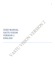
CMS (Central Monitoring System) USER’S MANUAL For safe use of system and to prevent product failure or accident, please read this manual carefully before use. Version : CMS ENG 2 3 Central Monitoring System INTRODUCTION CMS (Central Monitoring Software) is designed to control hundreds of local DVRs from the central monitoring room. Multiple DVRs are registered and monitored with maximum 128 split screens in a CMS. It can draw the needed videos and effectively monitor the videos by extra monitoring function. Especially, 16 E-MAP can be registered by multiple E-Map function and it provides the function needed to monitoring such as automatic pop up etc per each event. All the DVRs we provide are available to be monitored by CMS and it has functions to build the central monitoring structure. CMS presents advanced features as follows to fulfill effective central monitoring. 1. Multi-screen monitoring (Quadruple Display) 2. Maximum 1,024Ch display in one screen. 3. 16 E-MAP monitoring 4. Event Mapper : Special event caring windowns 5. Remote Search, Backup and full menu Setup 5. Dynamic IP support 6. Remote PTZ control CMS User’s Manual 2 Central Monitoring System CONTENTS INTERODUCTION………………………………………………………………………………………………………………2 1. PC REQUIREMENT…….…………………………………………………………………………………………………..4 2. PROGRAM INSTALLATION……………….…………………………………………………………………………..5 3. CMS LOGIN………………………………………………………………………………….….……………..……………..6 4. MAIN GUI………………………………………………………………………………………..…………………………….7 5. DVR REGISTRATION………………………………………………………………...…….……………………………..8 6. DVR REGISTRATION, DELETE, MODIFICATION………...………………………………………………....9 7. DVR REMOTE CONNECTION/ DISCONNECTION………………………………………………………10 8. REGISTERED DVR LIST FUNCTION………………………………………………..……………………………11 9. MULTI-CHANNEL DISPLAY…………………………………….…………………………………………………..,12 10. I FRAME STREAMING……………………………………………………………….……………….……………,.,14 11. CLONE………… …………………………………………………………………………………………………………….,,14 12. AUTO CON……………………………………………………………………………………………………….……..,,16 13. SEQ CON………………………………………………………………………………………………………….……...,16 14. SINGLE MODE....…………………………………………………………………………….…………….................17 15. EM(EVENT MAPPER)……………………………………………………………………………………..…….…...18 16. NASS(SCHEDULE BACKUP)……………………………………………………….……………………………..20 17. SCREEN CONTROL…………………………………………………………………..………………………………23 18. CH NET STATUS………………………….………………………………….……………………………….……….25 19. DISPLAY SETUP…………………………………………………………………………………………….…………..26 20. CAPTURE…………………………………….………………………………………………………….…….…………..26 21. BACKUP………………………………………………….………………………………………………………………...27 22. REMOTE SETUP…………………………………….………………………………………………………………….28 23. SOUND…………………………………………….…….…………………………………………………………………28 24. SEARCH………………………………….……….………………………………………………………………………...29 25. PTZ PRESET…………………………………………………………………………………………………………..……30 26. AUTO TOUR….……….……………………………….…………………………………………………….……...……32 27. RELAY OUT..…………………………………………………….………………………………………………………….33 28. E-MAP………..…………………………………………………….………………………………………………………….33 CMS User’s Manual 3 Central Monitoring System 1. PC REQUIREMENT According to the PC specification and internet speed, the CMS function can be limited. Minimum PC spec Recommended PC spec ㆍ CPU : Pentium4 3GHz ㆍ CPU : E6000 ㆍ Memory : 1G ㆍ Memory : 2G ㆍ VGA memory : 32M ㆍ VGA memory : 256M ㆍ HDD : 10G ㆍ HDD : 10G ㆍ OS: WINDOWS XP ㆍ OS: WINDOWS VISTA ㆍ DirectX 9.0C ㆍ DirectX 9.0C QUAD(Quadraple display) Monitoring Quadraple display is possible when the PC specification meets the requirements. It should be possible to install the 2 VGA card. [Note] CMS function updates may need the enhanced PC specification. CMS User’s Manual 4 Central Monitoring System 2. PROGRAM INSTALLATION The installation CD is enclosed in product carton box. You may download the updated version in future upon request. [1] Execute the “install.exe” from the installation CD. [2] If the installation program starts, execute the “CMS Program”. The language will be recognized automatically. Install it as per popup messages √ Read Me : Installation info is included. √ Quick Install (Typical) : It installs all the programs in CD as an order. √ CMS Program : It installs only the main CMS program. √ MS Backup Viewer : It supports the playback of backup files. √ Exit : It terminates the installation program. ☞ If the installation is completed, you can see the icon from the main screen. Please use the program after rebooting your PC. *Viewer program installation If you backup the image from the DVR, the viewer program is saving together with the image file but, if you didn’t save the viewer as an optional, you have to install the viewer additionally on your PC. CMS User’s Manual 5 Central Monitoring System 3. CMS LOGIN If you click the CMS icon from the main screen on PC, below log-in window shows. [1] The initial login password is NNNN. The login password is divided into 3 kinds of authority. USER PASSWORD ADMIN PASSWORD NNNN AUTHORITY All function on CMS is possible to use Except for the configuration (menu) POWER USER PASSWORD setup such as remote menu, E-Map, PPPP DVR registration), all other function is possible to use USER PASSWORD UUUU Only live monitoring is possible. [Note] The authority for CMS is the top priority. If you make the CMS log-in as ‘USER’, even if the DVR is logged-in as ADMIN, you only can see the live image through CMS. [2] CHANGE ADMIN PASSWORD : It changes ADMIN password “NNNN” √ CHANGE POWER USER PASSWORD : It changes POWER USER password “PPPP”. √ CHANGE USER PASSWORD : It changes USER password “UUUU”. CMS User’s Manual 6 Central Monitoring System 4. MAIN GUI There are 9 control panels on main CMS screen. [1] It shows CMS version. [2] It shows CMS image pictures. [3] DVR connection/ disconnection and registered DVR information. [4] It is for DVR Setup, Search, Backup, PTZ control etc., [5] It changed the split mode. [6] It is for the Registration, Delete or Modify the DVR information. [7] It is for Schedule Backup, Auto Connection, Sequence etc. [8] It shows network streaming status. [9] It terminates the CMS. CMS User’s Manual 7 Central Monitoring System 5. DVR Registration [1] If you execute it for the first time, “no registered recording device. Do you want to register?” message comes up. If you click “yes”, DVR registration menu opens. If you want to register the DVR after click “NO”, select the “DVR INFO” located on right-upper side. [Note] To register the DVR, CMS has to be logged on as ADMIN. [2] When you register the DVR, static IP user and Dynamic IP user setup is different so, please check it through your ISP. STATIC IP USER (Example) √ DVR NAME : The name can be made as per user’s disposal √ DVR ID : Input the same ID registered on the DVR. √ DVR PASS : Input the same password registered on the DVR. √ DVR IP : Input static IP of DVR ( If you don’t know, please check your ISP) √ DVR PORT : Input the port number registered on the DVR. √ DVR MODEL : Select the model name of the DVR you have. √ USE DDNS and DDNS ID doesn’t have to be configured in STATIC IP setup. √ When above process is finished, press the “ADD DVR” to complete the registration. Then, the list shows up the DVR list located right side. CMS User’s Manual 8 Central Monitoring System DYNAMIC IP USER (Example) √ DVR NAME: The name can be made as per user’s disposal √ DVR ID : Input the same ID registered on the DVR. √ DVR PASS : Input the same password registered on the DVR. √ DVR MODEL : Select the model name of the DVR you have. √ DDNS PORT : Select it √ DDNS ID : There is the own DDNS ID(Webcode) on each DVR. Please check from the DVR menu and input it. (*Menu on DVR System Information Web code) √ When above process is finished, press the “ADD DVR” to complete the registration. Then, the list shows up the DVR list located right side. 6. DVR Registration, Delete and Modification You can delete or modify the DVR registration info. [1] Modify the DVR info √ Select the DVR to be modified and click the “DVR INFO then, the relevant information show up as below. √ Once you modify the DVR information and click the “SAVE DVR”, the modified information is saved. (Example) CMS User’s Manual 9 Central Monitoring System [2] Delete DVR info √ Select the DVR to be deleted and click the “DVR INFO then, the relevant information show up as below. √ Click the “DELETE DVR” from below DVR information menu. (Example) 7. DVR Remote Connection/Disconnection [1] DVR Remote Connection There are two ways of DVR connection for remote monitoring. Double click the DVR name from the LIST to connect DVR. ② Select the DVR from the list and click the “CONNECT” icon. CMS User’s Manual 10 Central Monitoring System [2] DVR Disconnection √ Select the DVR list and click the “DISCONNECT”. 8. Registered DVR List DVR registration list shows the registered DVR, connection status, camera connection information etc., [1] DVR Information display √ The “GP”, “G”, “H”, “HD” is the name of the DVR. √ Alarm display : If the red alarm icon is blinking on the DVR list, it means the event happened on the relevant DVR. [2] Connection status display √ If the DVR is connected or tries to connect, the icon is flickered. (The icon flickers repeatedly) [3] Alarm display √ When an event is triggered, a red alarm icon is displayed on the DVR list. The event is triggered by motion, sensor, video loss, HDD error, audio recording. The red alarm flickers around 10 seconds and beeps as well. CMS User’s Manual 11 Central Monitoring System [4] If you click the “+” from the DVR list, you can see the camera information belongs to the relevant DVR. Only blank-checked channel can see the image.(Default is checked all) [5] Channel Covert √ If you click the camera icon, it turns to “X” and the camera image doesn’t show up on CMS. ( It applies when it was re-connected) √ It is nothing to do with the DVR unit but, it is concealing the image from the CMS itself. 9. MULTI-CHANNEL DISPLAY For multi-channel displaying in one screen when many DVRs are connected, it supports multi split channel display mode. It is optimized in WIDE monitor as well. CMS User’s Manual 12 Central Monitoring System [1] MAX : It makes the live image to fully fit the screen. “ESC” returns to previous. [2] Split mode selection The displaying and monitoring is possible as per the user’s request. (Example) If you press “2” , it displays as squared so, it show 2X2 screen. If you press “4” , it displays as squared so, it show 4X4 screen. [3] It is the split mode in Wide Display. [4] This is user’s split mode as per their discretion. 1) Click the “DISPLAY” on the right below of the screen. CMS User’s Manual 13 Central Monitoring System 2) Select the split mode you want from the left-below menu. UM (Horizontal) : Horizontal displaying channel selection. UM (Vertical) : Vertical displaying channel selection. 3) If you select “UM” in the menu, the screen is switched into split mode by a user 10. I FRAME STREAMING Still Image [‘I’ Frame] : When connecting lots of DVRs, it’s not available to see the normal video. In this case, if “Still Image” is selected, streaming mode is changed from video to image. This can reduce the network overload as it transmits only “I” frame. 11. CLONE (Grouping Function) CLONE function floats the new CMS program so, you can float 3,4,5,6.. CMS screen. If you have multi-monitor, you can move the cloned CMS to the monitor 2, 3, 4, … CMS User’s Manual 14 Central Monitoring System Since this CLONE screen is saved, if you click the CLONE in next connection, the same saved CLONE is floating again. [Feature and usage] √ Each different DVRs can be shown as a single connection and this function could be used as a ‘VIRTUAL DVR’. For example, if you click the specific camera from DVR1 and specific camera from DVR 2 and specific camera from DVR 3… After disconnect all the DVRs and connect all DVRs again then, all selected specific channels are shown. Click the CLONE then, CLONE 1 is the VIRTUAL DVR No. 1. (Grouping) √ With CMS placed to each monitor, controlling each DVR is fast and handy. √ Multi E-map floating is possible. [1] If you click the “CLON”, the connection way looks same as the new CMS connection. [2] The connection can be made by the ADMIN password. Then, you will see the CLONE1. This means the first clone so, if you click the ‘CLONE’ again, CLONE2 is floating. If you disconnect and connect again, and click the ‘CLONE’, the saved ‘CLONE’ will be floated again. CMS User’s Manual 15 Central Monitoring System 12. AUTO CON Once you check the listed DVR and click the AUTO CON, all checked DVRs are connected automatically. (But once the CMS is terminated, AUTO CON function is released ) [1] Select the DVR automatically connecting in the registered DVR list. [2] If you click “AUTO CON”, all the selected DVRs are automatically connected. 13. SEQ CON It makes the selected DVRs sequence during the selected time. Click the “SEQ CON” for working. If it works, the color of button turns blue. [1] Select the DVRs to be sequenced. CMS User’s Manual 16 Central Monitoring System [2] Set the number of device and duration time for sequence. ☞ Seq Con Num : Select how many DVRs’ videos are shown in a time. ☞ Seq Con Int : Select the duration time for sequence. [Note] SEQ CON works only when at least 2 DVRs are selected. [3] If you checked 3 DVRs, and set “Seq Con Num =1” , “Seq Con Int=10”, it shows DEMO-1 DVR for 10 seconds and sequencing to DEMO-2 and DEMO-3. [4] If you checked 3 DVRs, and selected “Seq Con Num =2” , “Seq Con Int=10”, it shows DEMO-1 and DEMO-2 in one screen for 10seconds and, sequencing to DEMO-3 and DEMO-1, DEMO-2 and DEMO-3. [5] If you click the “SEQ CON”, sequencing is started and the icon turns blue. If you click again, it is released. 14. SINGLE MODE CMS User’s Manual 17 Central Monitoring System SINGLE MODE is needed when there is no multi-DVR connection. If you connect it based on SINGLE MODE, the connection is automatically made as per the original DVR split. (16Ch/ 9Ch/ 8Ch/ 4Ch). 15. EM (Event Mapper) EM displays the event information and image to the separate CMS screen. So, although there are many DVRs are connected, you can easily catch the event information with this advanced monitoring function. [1] For your applying the Event mapper function, double click the DVR list while pressing the “CTRL” key. Then, it will ask whether you want to change the connection mode click ‘YES’. [2] If the Event Mapper function applies to the relevant DVR, red “E” icon appears. [3] Select the DVRs to use in Event Mapper function [4] While the selected DVR is connected, if you click ‘EM’ icon, then extra EM window is opened. [Note] If you connect the DVR with ‘Event Mapper mode’(EM), only “WAITING DATA” could be CMS User’s Manual 18 Central Monitoring System shown. It’s because if you select the DVR as ‘EM’ mode, the image only can be shown when there is real EVENT happen. So, EVENT MAPPER function has to be used in proper way and purpose. [5] Since the user can see the EVENT IMAGE only from many images from many connected DVRs, it gives you the effective monitoring. [Event Mapper description] √ Auto Scroll : If the new event happen, the list updates automatically. If you want to search the certain image or event list, you’d better to uncheck the “Auto Scroll”. √ Update Item : The event list or image is not updated on the screen. √ Write Log : It saves the event list as log file. √ Write Image : It saves the event image automatically on the PC. Since it occupies the HDD space on your PC, you have to be very careful when you use. √ CONNECT LIVE : Once you select the ‘LIST’ and click the “CONNECT LIVE”, it shows the relevant DVR screen. √ VIEW CHANNEL : Once you select the ‘LIST’ and click the “VIEW CHANNEL”, one channel is floating as a VIEW channel. √ DIRECT SEARCH : Once you select the ‘LIST’ and click the “DIRECT SEARCH”, it searches the CMS User’s Manual 19 Central Monitoring System relevant event. [Note] If you uncheck the ‘Update Item’ you cannot use “write log” and “write Image”. 16. NASS (SCHEDULE BACKUP) NASS supports the remote schedule backup. Scheduele Backup enables multiple users to set automatic backup at their favorable time. [1] Click the “NASS” button for schedule backup. [2] Register the DVR for schedule backup. There are two ways to make the registration. (Recommandation : The 2nd way is more convenient) 1) 1st Way (Manual Input) After executing NASS, click the right button of your mouse in Nass Device Manage. Then click “Add Device”. CMS User’s Manual 20 Central Monitoring System If the window entering DVR registration info DVR is opened, then enter same value to each blank like when registering the DVRs on CMS. 2) 2nd Way (Automatic Input) When clicking the right button of your mouse on the product registration list of CMS, if you click “Add Device To Nass”, then it is registered to NASS automatically. [3] How to set NASS backup 1) Load the recorded data Check how much recorded data is in the DVR before starting NASS backup CMS User’s Manual 21 Central Monitoring System ① Select the DVR registration name from the list. ② Click “Record Information” (It tries connection to a DVR remotely) ③ It carries on the work to load the recording information. ④ It displays the first and the last time of the whole recording time. ⑤ It shows the recorded data with calendar. ⑥ It displays the date of today. 2) Backup ① Select the starting date and time for backup (Available to select from calendar by clicking the tab) ② Select the ending date and time for backup (Available to select from calendar by clicking the tab) ③ Select the folder for saving ④ Start the backup ⑤ If you click “STOP” during backup, it stops. (If the backup is completed, it automatically stops.) ⑥ It shows the procedure of backup. CMS User’s Manual 22 Central Monitoring System ⑦ After backup, you can use it when you open the backup folder. ⑧ If you want to make more detailed backup setup, you can use “Advanced Setup”. Note: It continues the backup until the work is completed. 3) ADVANCED SETUP ① “Select the channel, Event filter” enables to back up only the selected time with selected channel and event. ② “Select the backup schedule” realizes to select the day of week and particular time period. (Example) Above settings proceed the backup from 3pm to 6pm on Monday, Wednesday and Friday only. And it doesn’t carry on backup in other time period. The backup is progressed by being followed by previous backup data. 17. SCREEN CONTROL CMS provides various display control for monitoring considering user’s convenience. [1] Channel Viewer It enlarges the specific channel while monitoring ① One channel pop-up : Press “Ctrl” key and double click the left button of mouse on the specific channel which want to enlarge. CMS User’s Manual 23 Central Monitoring System ② On the pop-up window, double click the left button of mouse, S-PIP screen which is entire channel of DVR. . ③ One channel full mode : Double click the left button of mouse on the specific channel which want to see full mode. ( If user want to return split mode, double click again. ) [2] S-PIP ① Shift + a particular channel If you double click a channel while pressing “Shift” key, the extra whole split screen is created. CMS User’s Manual 24 Central Monitoring System ② Ctrl + a particular channel If you double click a particular channel while pressing “Ctrl” key, the channel screen is pop up. Then, if you double click the popup screen, the extra whole split screen is created. [3] DIGITAL ZOOM This function is providing software digital zoom In/Out of target point on the screen. Pixels or mosaic could be seen as screen is zoomed in. ZOOM IN ZOOM OUT [How to use] CMS User’s Manual 25 Central Monitoring System Select single full channel and place a mouse cursor where you want to zoom in. By using scroll wheel of the mouse, the screen can be zoomed in and out. Double click left mouse button to return to normal screen. [Note] * Digital zoom function is not available on multi channels screen. * Digital zoom function is not available on S-PIP screen. 18. CH Net Status The color change as per the streaming frame. [1] It shows the streaming status in Live mode. The channel information shows as per the number of DVR channel. [2] Distinguishing as per the color. ☞ Red : 0~1 frame streaming. ☞ Yellow : 2 frames ☞ Green : Over 3 frames 19. Display Setup This menu is to select various display options and resolution info on screen. (Selected button CMS User’s Manual 26 Central Monitoring System changed in blue color) [1] TIME / CHANNEL MODE: Time and Channel information display on screen.. [2] MOTION/SENSOR/V LOSS / REC: Motion, Sensor, Video loss and Recording status display. MD : Motion Detection SS : Sensor Detection VL : Video Loss MU : Museum Detection NU : Unattanded Detection [3] FPS / RESOLUTION: Frame, Resolution info [4] SHOW ALL: Display all above (1)~(3) information. [5] HIDE ALL: Conceal all display information. 20. CAPTURE This function is to capture current screen image and save into PC. √ Saving folder: C:\MY DOCUMENTS\CMS\CAPTURE. ₩ 21. BACKUP There are two backup modes, which is Live Backup and Schedule Backup. Live Backup is saving CMS User’s Manual 27 Central Monitoring System the current live screen and Schedule Backup is archiving the data by selecting the particular time period. [1] Live Backup It proceeds from the time to click the backup button to the time to click the backup button again. √ Select directory to save achieved backup data. (It saves in default directory if no director is selected) √ Input file name. (If file name is not assigned, it will create suggesting file name automatically) √ Select the channels to backup. √ Click “OK” to confirm the setup. (If backup starts, “Backup” is displayed on each screen.) √ Backup starts when you click “Backup” button and ends as “Backup” button is clicked again [2] Schedule Backup It archives the data in the hard disk drive by selecting the particular time period. 22. REMOTE SETUP Remote setup provides remote users to call DVR main menu to change setup information. CMS User’s Manual 28 Central Monitoring System [Note] Regarding this remote setup, please refer to the instruction of each DVR for the setup as it is different per model. 23. SOUND Audio remote listening and 2 way audio communication is available. (Setup Menu when a DVR supports 16ch audio) (Setup Menu when a DVR supports 4ch audio) [1] Select the channel to switch on the audio [2] Switch off all the channels’ audio [3] It enables to automatically hear the audio of selected channel only on the screen. [4] Switch on the 2 way audio communication [5] When a selected event is triggered, it beeps for 10 seconds. - MD : When a motion is detected, it beeps for 10 seconds. - SS : When a sensor is triggered, it beeps for 10 seconds. CMS User’s Manual 29 Central Monitoring System - VL : When a video loss is happened, it beeps for 10 seconds. - UA : When a something dangerous material is deteched, it beeps for 10 seconds. - MU : When a lost item is detected, it beeps for 10 seconds. 24. SEARCH The remote search by TIME, EVENT, CALENDAR is available. The instruction is different per model. (Example) [1] Search by time. [2] Search by event [3] Search by calendar. [4] Playback controller. [5] “LIVE” button: It turns to live screen from Playback. Playback controller [1] Fast reverse playback (Faster per each click) [2] Reverse playback (x1) [3] Reverse playback by 1 frame per each click [4] Pause [5] Playback by 1 frame per each click CMS User’s Manual 30 Central Monitoring System [6] Slow playback [7] Normal playback (x1) [8] Fast forward (Faster per each click) [Note] Regarding Remote Search, the displayed image is different from the DVR’s, but the way to use is almost same. As functions per model are different, please refer to the instruction manual of each DVR 25. PTZ PRESET On CMS program, a user can remotely operate PTZ cameras and the function includes ZOOM, FOCUS, PRESET, TOURING. [1] PTZ camera speed selection. √ SPEED X1, SPEED X2, SPEED X4 PTZ speed can be selected while PTZ moving, Zooming or Focusing [2] PTZ camera direction control and Functions PTZ camera moving direction can be easily controlled by mouse click. [Functions] √ IRIS OPN : It opens IRIS function √ IRIS CLS : It closes IRIS Function √ TOUR START : It switches on Touring function. √ TOUR STOP : It switches off Touring function. CMS User’s Manual 31 Central Monitoring System [3] AUTO FOCUS of PTZ camera √ ZOOM : Zoom In/Out of PTZ camera. √ AUTO FOCUS ; Automatic camera focusing. √ FOCUS : It focusing the camera. ZOOM IN/FOCUS IN ZOOM OUT/FOCUS OUT [4] PRESET PRESET function is to call initially saved camera positions of PTZ camera. Max. 16 preset positions can be saved on CMS. √ PRESET MOVE : If you click any button in the current location, the PTZ camera moves to the location as it is saved. √ PRESET SAVE : After fixing the location for a PTZ camera, if you set a number in the PRESET SAVE menu, the location info is saved. 26. AUTO TOUR CMS User’s Manual 32 Central Monitoring System This function is for intensive (repeat) monitoring two or more preset positions of PTZ. “AUTO START” and “TOURING START” are available. AUTO START It is intensive monitoring against two PTZ preset positions repeatedly in order. Dwell time on each preset position can be selected. ① START PRESET : Select first preset position. ② END PRESET : Select second preset position. ③ INTERVAL : Select dwell time at each position. ④ AUTO START : It starts automatic monitoring between the PTZ camera’s two preset positions as per configured. TOURING START It is intensive monitoring by repeat touring of selected position of PTZ. ⑤ Save selected position to PRESET No. on the list. ☞ SKIP : This No. will be skipped from TOURING. ☞ 1~16 : Save PTZ camera positions to each PRESET No. on the list. ⑥ INTERVAL : Select dwell time at each position. ⑦ TOURING START : It starts touring to all the preset positioned list as per the dwell time. [NOTE] To use TOURING function, at least 3 preset positions or more are required. 27. RELAY OUT CMS User’s Manual 33 Central Monitoring System A user can remotely control the relay. [1] Select the Relay number. If the number is over 16, then have to input the number by yourself. [2] Select the duration time for Relay out. - Infinite : No limited time - You can select 5/10/30 seconds or 1/10 minutes or 1 hour. - You can also input the particular second. [3] Select ON/OFF for Relay out. 28. E-MAP This is an electronic map display to provide efficient monitoring viewing the positions and status of events by cameras, sensors and DVRs on the map. CMS User’s Manual 34 Central Monitoring System [1] It provides selectable maximum 16 E-maps on screen, and double click will maximize the map (Double click of full E-map returns to multi map) [2] Event Icon tool Collection of “Camera”, “Sensor”, “DVR” icons used for E-map configuration [3] E-map list It is for importing the new E-MAP image file from the PC or, external device. [4] POP UP : The image window will be shown on the e-map when alarm triggered. [How to register E-map] To use this function, BMP file E-map image must be registered on the E-map screen. CMS User’s Manual 35 Central Monitoring System Browse E-map image file by selecting “IMPORT MAP”, and input new E-map name on the list. By the same procedure, additional map can be registered. (Double click of e-map title can modify the title description / DELETE key is for selected E-map removal from the list) [E-map Image Positioning] By using mouse, select an E-map title and drag onto the position where you want place among 16 split map screen, then connected icon image is registered automatically. (Drag and Drop) [E-MAP Icon Positioning] √ positioning the icons (DVR, Camera, Sensor) to a E-map, make it full screen by double click. √ Put the icons by dragging the mouse onto the E-map. √ For detailed configuration, option window will be opened from the positioned icon. CMS User’s Manual 36 Central Monitoring System (Icon selection) ① Select DVR : Select DVR where the camera is connected. ② Select channel : Select channel where the camera is connected. (DVR selection) Aside from Camera or Senor icon display on E-map, separate DVR icon can be positioned on the E-map. The DVR icon will be blinking any event which is happening on the same DVR. [Delete Icon on E-map] Select the icon and press “DELETE” key on PC keyboard. [E-Map Automatic Pop-up] The icon on E-map will be blinking when an event happens then, user can view its image by double clicking the icon. It shows the relevant channel image. CMS User’s Manual 37 Central Monitoring System √ To be enable auto popup, check in the PopUp box. √ When click the camera icon, image will be shown. CMS User’s Manual 38