1
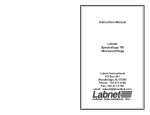
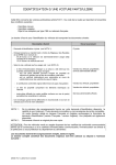
Installation and User Manual
Tranberg 4900 Commander Control system
Version 2.3
TRANBERG AS
October 2015
Copyright © 2005 – 2015 TRANBERG AS. All rights reserved.
Document Information
Document Title:
Installation and user Manual TEF 4900 Commander
Control System
Version:
2.3
Document Type:
Description
Status:
Issued for approval
Amendment Date:
April 2007
Issued By:
TRANBERG AS, Technical dept.
Summary of Revisions (abbr.)
Date
Version
Status
Issued By
June 2006
1.2
Issued for use
TRANBERG AS
Technical dept.
September 2006
1.3
Issued for use
TRANBERG AS
Technical dept.
November 2006
1.4
Issued for use
TRANBERG AS
Technical dept.
January 2007
1.5
Issued for use
TRANBERG AS
Technical dept.
June 2009
2.0
Issued for approval
TRANBERG AS
Technical dept.
March 2011
2.1
Issued for use
TRANBERG AS
Technical dept.
May 2015
2.2
Issued for use
TRANBERG AS
Technical dept.
October 2015
2.3
Issued for use
TRANBERG AS
Technical dept.
Copyright © 2005 - 2015 TRANBERG AS. All rights reserved. Page ii of 40
TRANBERG AS has made every effort to provide accurate information, but makes no claims as to the accuracy or
completeness of this information. TRANBERG AS disclaims liability for errors, omissions, misinterpretation or misuse of this
information by others.
TRANBERG, Commander and other names are either trademarks or registered trademarks of TRANBERG AS.
Copyright © 2005 by TRANBERG AS Restricted information
Table of Contents
TABLE OF CONTENTS...................................................................................................... IV
CHAPTER I.
INTRODUCTION ....................................................................................... 6
SECTION 1.01 GENERAL INFORMATION ............................................................................ 6
CHAPTER II.
TECHNICAL OVERVIEW .......................................................................... 7
SECTION 2.01 INTRODUCTION ......................................................................................... 7
SECTION 2.02 SYSTEM OVERVIEW .................................................................................. 7
CHAPTER III.
FUNCTIONAL DESCRIPTION .................................................................. 8
SECTION 3.01 INTRODUCTION ......................................................................................... 8
SECTION 3.02 BUTTONS AND LEDS ON PANEL .................................................................. 8
Text and graphics on panel ............................................................................................... 9
Button quantity and panel size........................................................................................... 9
Button placement .............................................................................................................. 9
Button functionality ............................................................................................................ 9
Button and led status ....................................................................................................... 11
Button state diagram ....................................................................................................... 11
Button configurations ....................................................................................................... 12
Spare lamp test ............................................................................................................... 13
CHAPTER IV.
MASTER CPU ......................................................................................... 14
SECTION 4.01 CONNECTIONS ....................................................................................... 14
Inputs ............................................................................................................................... 14
Outputs ............................................................................................................................ 14
Power supply ................................................................................................................... 14
LED indicator ................................................................................................................... 14
SECTION 4.02 VDR GATEWAY ...................................................................................... 15
SECTION 4.03 SCADA GATEWAY ................................................................................. 18
CHAPTER V.
PANEL ..................................................................................................... 23
SECTION 5.01 OVERVIEW ............................................................................................. 23
Hardware ......................................................................................................................... 23
Buttons and LEDs............................................................................................................ 24
Settings on the panel ....................................................................................................... 25
Non-volatile memory........................................................................................................ 26
Connections..................................................................................................................... 26
Copyright © 2005 – 2015 TRANBERG AS. All rights reserved. Page iv of 40
CHAPTER VI.
OUTPUT MODULES ...............................................................................27
SECTION 6.01 OVERVIEW .............................................................................................27
Common hardware .......................................................................................................... 27
Relay output modules ...................................................................................................... 29
Analog output modules .................................................................................................... 30
Connections and fuses .................................................................................................... 31
CHAPTER VII. INSTALLATION .......................................................................................33
SECTION 7.01 INTRODUCTION .......................................................................................33
SECTION 7.02 POWER CABLES TO MODULES ..................................................................33
SECTION 7.03 COMMUNICATION CABLES TO MODULES ....................................................33
SECTION 7.04 MAIN POWER SUPPLIES ...........................................................................34
SECTION 7.05 TERMINATION OF SYSTEM ........................................................................34
SECTION 7.06 TERMINATION OF OUTPUTS ......................................................................35
SECTION 7.07 APPLYING POWER FOR THE FIRST TIME ....................................................36
SECTION 7.08 TESTING THE SYSTEM .............................................................................36
SECTION 7.09 FAILURES ...............................................................................................37
CHAPTER VIII. APPROVALS ..........................................................................................39
SECTION 8.01 APPROVALS ...........................................................................................39
CHAPTER IX.
ADDITIONAL INFORMATION .................................................................40
SECTION 9.01 TECHNICAL CLARIFICATIONS ...................................................................40
Copyright © 2005 - 2015 TRANBERG AS. All rights reserved. Page v of 40
Chapter I.
Section 1.01
Introduction
General Information
The 4900 Commander is a new control system developed by TRANBERG AS.
TRANBERG has a long history of designing and manufacturing navigation lights
controllers for medium sized and large vessels. The traditional design principle has been
a direct control of each channel, meaning that the cable for each individual lantern
needs to be laid from the lantern to the actual controller. This is both a costly and
challenging task.
The Commander has been developed with greater flexibility in mind, and in particular
with the objective to avoid pulling each lantern cable into the bridge. The concept is
therefore based upon the industry-proven RS-485 network with a number of nodes
connected to this.
A node may in this respect be a control panel, a relay output module, the master CPU
and more. Each node is given a unique address and the corresponding action between a
single button and the panel is defined in the configuration of the system.
Copyright © 2005 – 2015 TRANBERG AS. All rights reserved. Page 6 of 40
Chapter II.
Section 2.01
Technical overview
Introduction
The TEF 4900 Commander system consists of three main components:
•
Master CPU
•
Panels
•
Output modules
The three main components are interconnected via a RS-485 network. Each node has a
unique address, and the Master CPU controls the network traffic by allowing one and
only one node to ‘talk’ at any given time.
Section 2.02
System overview
Generic system diagram:
Panel 1
Panel 2
Panel 3
RS-485 Network
Master
CPU
Config data
RS-485 Network
Output module 1
Output module 2
Output module 3
Copyright © 2005 - 2015 TRANBERG AS. All rights reserved. Page 7 of 40
Chapter III.
Section 3.01
Functional description
Introduction
The TEF 4900 Commander remote control system can have to up to 7 operator panels
connected in one system.
Each operator panel consist of up to 64 buttons, each stacked up to 8 rows. The panels
are backlit for easy reading of text and graphics, in daylight as well as at night. In
addition, up to 16 relay output modules may be connected, providing a flexible control
system with current sensing feedback from the outputs.
Application areas:
The Commander system is designed specifically for marine use and has a contemporary
design with backlit front panels. The design concept allows customization of number of
buttons, text and graphics, and is therefore useful for a wide range of customer-specific
navigation and signal lights controllers.
Communications:
Robust, industry proven and noise immune RS-485 is used for communication between
control panels, Master CPU and relay output modules. As an option, a communication
interface to Voyage Data Recorder and/or vessel control system will be available,
allowing data recording and external reset of alarms. The system supervises the
integrity and issues an alarm if a node fails to respond in the network.
Features at a glance:
•
•
•
•
•
•
•
•
•
24 VAC/VDC and 230 VAC versions
W ith or without current sensing capabilities on outputs
Optional compensation for voltage loss in long cable feeds
Analog output module: Combined dimmer and flasher, triac-based, 230VAC
Operator panels with dimmable backlight
Audible and flashing led alarm, with potential free relay alarm contacts
RapidAction™ buttons: One touch turns on and off dedicated outputs
GroupSelect™ buttons: Similar to radio buttons (select one buttons in a row)
Optional functionalities include VDR (Voyage Data Recorder) and/or SCADA
(Supervisory Control And Data Acquisition)
Section 3.02
Buttons and leds on panel
The TEF 4900 Commander is designed to be extensively configurable. This is in order to
meet customer requirements with a minimum of production or engineering changes.
Configuration options:
•
Text and graphics on panel
Copyright © 2005 – 2015 TRANBERG AS. All rights reserved. Page 8 of 40
•
•
•
•
•
Button quantity and panel size
Button placement (installed or not installed in the grid pattern)
Button functionality (ranging from one single channel to a group of output
changes)
Output module type (analogue, discrete relay or relay with current sensing)
Manual or automatic changeover to spare outputs
Text and graphics on panel
The panels have backlight with manual dimming functionality. The text and graphics are
laser engraved, providing the users with clear and precise information, readable in
daylight as well as in the dark.
The construction consists of a machined, black aluminum frame with a recessed button
surface made of Lexan. The Lexan film is painted on the reverse side as well as laser
engraved on the same side. This ensures a very durable front.
Button quantity and panel size
The panels come in five different lengths, depending on the number of buttons. All
panels have the same height.
The buttons are injection molded in black color. A Lexan film in various colors is
inserted in a recess on top of the button. All button switch elements are of the metallic
dome type.
Button placement
Buttons are placed in a grid with 8 positions vertically and from 3 to 8 horizontally.
Buttons may be left out for clarity. This has no impact on software or any other settings.
Button functionality
Each button has two leds: One green and one red. Via software commands, these may
light up in a number of combinations: Off, steady on or flashing.
A single press on a button may have several functions, depending on the on the
configuration, button status, and the time the button has been pressed (short / long).
In general, there are four ‘normal’ states of a button:
•
Off. No leds will light up.
Copyright © 2005 - 2015 TRANBERG AS. All rights reserved. Page 9 of 40
•
•
•
Rapid green flash: The panel awaits a confirmation from the output module that
the corresponding output has turned on.
Continuous green: The output module has confirmed that the corresponding
output has been turned on.
Slow green flash: The corresponding spare output has been turned on and is
confirmed.
Failure combinations include:
•
•
•
Flashing red and green: The output channel (relay) reports a malfunction (broken
fuse or lamp) on the main output (e.g. main lantern). The buzzer will sound. This
is an unacknowledged alarm. W hen pressed at this stage, the button will flash
green and the spare output will be switched on.
Flashing red: The output channel (relay) reports a malfunction (broken fuse or
lamp) on the spare output (e.g. spare lantern). The buzzer will sound. This is an
unacknowledged alarm. W hen pressed at this stage, the button will light up with
a continuous red light.
Continuous red light: The spare output is defect. The panel must be turned off to
reset this state.
Depending on the configuration, a single push on a button may turn on or off a number
of outputs (and panel leds) to accommodate the needs. This yields a high density in
functionality, while simplifying the tasks of the user. As an example, one press on a
single button may ‘remote’ operate a selection of other buttons, as if the user pressed
each and one of these. In any case the user will have control over each single button by
turning this on or off.
See the two chapters Button and led status and Button state diagram over the next two
pages.
Copyright © 2005 – 2015 TRANBERG AS. All rights reserved. Page 10 of 40
Button and led status
W ith reference to the description on the previous page, this is a summary of the button
functionality and the corresponding led status, including alarm buzzer.
State
Effect
Outputs associated with
this key will be turned off.
Led
Green and red led off.
0
Description
Nothing (off). The default
position of any button.
A normal press on a key
(< 5 seconds).
The output module will
receive a message to turn
on the respective (main)
output.
Rapid green flash.
1
A long press on a key (> 5
seconds).
Not confirmed.
The output module will
receive a message to turn
on the respective (spare)
output.
Rapid green flash, each 4
blink is dark.
Main output is confirmed
on.
The green led will light up
continuously.
Steady green light.
3
Spare output is confirmed
on.
The green led will flash
slowly.
Slow green flash.
4
5
Main output reports a
malfunction.
Unacknowledged alarm.
The buzzer will sound and
both the green and red
leds on the button will
flash.
Alternating red and green
flash.
Spare output reports a
malfunction.
Unacknowledged alarm.
The buzzer will sound and
the red led on the button
will flash.
Rapid red flash.
6
7
Spare output is defect and
has been confirmed by the
user.
The buzzer will stop and
the red led will turn on
continuously.
Steady red light. Turn off
panel to reset.
Not confirmed.
2
th
Rapid flash: 2 flashes per second.
Slow flash: 1 sec on, 1 sec off.
Button state diagram
W ith reference to the table above, the button states operate in a fixed state process.
State 0 is the default state where both the green and red led on a button is turned off
and associated outputs are in an off position.
The left branch on the diagram below shows the states when the user wants to turn on a
main output, e.g. the main lantern. By pressing the button for less than 5 seconds, the
button changes to state 1. In this state a message is sent to the corresponding output,
Copyright © 2005 - 2015 TRANBERG AS. All rights reserved. Page 11 of 40
and the led flashes rapidly awaiting a confirmation from the output module. Another
press on the key at this state will return to state 0 and a message to turn the output off.
All short dotted lines show states from where an output may be turned off.
The two long dotted lines indicate two options: Depending on whether an automatic
switch-over to a spare lantern is present and configured the line from 5 to 2 indicates
that it will turn on the spare lantern. If no spare lantern is present and configured, the
line from 5 to 7 indicates that the red led will turn on steady to indicate that the
corresponding lantern is defect and no spare is available.
0
1
2
3
4
5
6
Turn off
panel
7
Button configurations
Besides regular button functionality as described in the table above, the flexible
configuration of the Commander allows buttons to be defined as RapidAction™ buttons
or GroupSelect™ buttons.
RapidAction™ buttons: One touch on such a button turns on and/or off dedicated
outputs and the corresponding buttons green leds, while no led will lit up in the
RapidAction™ button itself. The button merely acts as a hot key, simplifying standard
operations, such as turning on sailing lanterns or anchor lanterns.
GroupSelect™ buttons: Similar to radio buttons on computer software. The user press
one such button and the other buttons in the row will turn off all leds, while the green led
on the GroupSelect™ button that has been pressed will light up. This functionality may
be used for setting a dimmer level, e.g. with four buttons that allows four settings/levels.
For navigation lights control system, the first button column at the panel is normally
used for RapidAction™ functionality, named F-keys at the panel. The function of F-keys
is software configurable and will switch on and off a predefined set of outputs.
Copyright © 2005 – 2015 TRANBERG AS. All rights reserved. Page 12 of 40
The standard setup for F-keys is:
F-key
At Sailing
At Anchor
NUC
RAM
Towing <200m
Towing >200m
ROV Port
ROV Stbd
Outputs switched on
Outputs switched off
Masth. F./A., Port, Stbd, Stern
Anchor F./A.
All NUC
All NUC
All RAM
Masth. F., Port, Stbd, Stern
Tow/Masth.2, Tow Stern
Anchor F./A.
Masth. F./A., Port, Stbd, Stern
All RAM
Masth. F., Port, Stbd, Stern
Tow/Masth.2, Tow/Masth.3, Tow Stern
All Red ROV Port
All Green ROV Stbd
All Green ROV Port
All Red ROV Stbd
Masth. A
Tow/Masth.3
Anchor F., Anchor A.
Anchor F., Anchor A.
Masth. A.
All Green ROV Port
All Red ROV Stbd
All Red ROV Port
All Green ROV Stbd
Spare lamp test
Test of individual spare lamp:
1
Turn the respective circuit off.
2
Press and hold the respective button for min. 5 seconds.
3
Release button and spare lamp turns on.
Test of all spare lamps simultaneously:
1
Panel in standby mode.
2
Press and hold “on/standby” button for min. 5 seconds and while still “on/standby” is
pressed, press “backlight level” button. (Tip: While “on/standby” is pressed, press
“backlight level” repeatedly till spare lamp test mode starts.)
3
All spare lamp outputs are switched on.
4
Press “on/standby” to stop test.
Spare Lamp Test
On / Stby
Backlight
Level
Main Supply Out
Emcy. Supply Out
Alarm
Silence
Indicator lights, buttons:
Rapid green flashing: Circuit on, unconfirmed status.
Green steady: Main lamp on.
Slow green flashing: Spare lamp on.
Red flashing: Unacknowledged alarm.
Red Steady: Acknowledged alarm.
Copyright © 2005 - 2015 TRANBERG AS. All rights reserved. Page 13 of 40
Chapter IV.
Section 4.01
Master CPU
Connections
Only one Master CPU may be connected to a network.
Inputs
The master CPU has one digital input, 24VDC galvanic isolated. It is used as an Alarm
Silence Input function, allowing external equipment to silence the panel buzzer. It is
activated with a rising edge on the input (from 0 V to 24 V).
Outputs
The module has two single pole change-over relays. The Alarm Output relay is
energized in the inactive state, in order to signal a total power loss to an external
system. The relay will activate when an alarm condition is present, either power loss,
output failure or communication errors on the bus (no messages from panel or
modules). The alarm conditions are indicated on the panel with flashing red or steady
red LED indicators.
For faults which can be cleared by switching over to a spare or second power net, the
alarm output will be deactivated when the alarm is acknowledged (This applies to
outputs / lanterns with a spare, and for main (1) and emergency (2) power net). This
makes it possible to indicate several alarm conditions to the external system.
The second relay provides the Alarm Silence signal. This relay gives a pulse of about 1 2 seconds when the Alarm Silence button on the panel has been operated.
Power supply
The Master CPU can be connected to up to 4 power supplies (24 VDC), which are
connected in parallel via a set of diodes. This combined power output supplies the
panels and output modules. The power inputs are monitored by the Master CPU and
their states are signaled to all connected nodes via the RS- 485 network.
LED indicator
The green Activity LED is flashing under normal conditions. This indicates that all nodes
(relay modules and panel) are responding correctly.
If this LED is constantly lit it indicates that minimum one node is not responding. This
may be due to a broken communications cable, a faulty module or a combination of
both. If this happens, the Alarm relay will be activated, the alarm buzzer in the panel will
Copyright © 2005 – 2015 TRANBERG AS. All rights reserved. Page 14 of 40
sound and the indicator in the Alarm Silence button will flash continuously (provided the
connection towards the panel is ok). See also Chapter V Panels, Section 5.01 Overview,
Power Supply Monitoring.
Section 4.02
VDR gateway
In order to send information to a VDR (Voyage Data Recorder) onboard the vessel, a
VDR gateway module may optionally be installed in the Master CPU unit. This device
passively listens to the network traffic and sends out information about the status of the
system and the various output modules.
The VDR gateway sends out two types of messages, 1) system status messages
according to a proprietary Tranberg protocol, and 2) alarm messages according to
NMEA-0183 ALR and ACK messages.
Electrical interface
•
•
•
Baud rate: 38.400 bps
Data bits: 8N1
Electrical: Isolated RS-422, output only
System status messages
2
3
4
5
6
7
8
9
10
11
12
13
14
15
16
17
18
19
20
21
22
$PTRA
1
2
1
1
1
1
C
5
0
1
1
1
4
4
4
4
1
*
1
2
0
$PTRA
ComStatus
FailCode
Net 1
Net 2
Net 3
Net 4
Node type
Node number
Manual o’ride
Channel 8
Channel 7
Channel 6
Channel 5
Channel 4
Channel 3
Channel 2
Channel 1
*
Checksum H
Checksum M
Checksum L
The output string is a proprietary NMEA-0183 structure with the following setup:
1
Example:
$PTRA,1,2,1,1,1,1,C,5,0,1,1,1,4,4,4,4,1,*,1,2,0
Packet length: 26 characters (normal), plus commas, carriage return and new line. Total
number of characters (including commas) sent are 47 characters, plus carriage return
and new line. Packet lengths are shorter in case of irregularities (see later in this
document).
Repetition rate: Packages are sent continuously at a rate of approx. 5-10 packets per
second.
Explanations:
$PTRA: A fixed proprietary beginning of the telegram (Proprietary TRAnberg)
Copyright © 2005 - 2015 TRANBERG AS. All rights reserved. Page 15 of 40
Comma: A comma sign (,)
Asterix: An asterix sign (*)
ComStatus: If minimum one node does not respond. 0 = Failure, 1 = Ok
FailCode: Common code for a fail on the module. 0 = Disregard, 1 = Ok, 2 = Net failure,
3 = Output failure, 4 = Net and output failure. If node is set to Manual override, the code
is 3 or 4.
Net1 – Net4: Status of the (up to) 4 independent power supply networks. 1 = On, 0=Off.
Node type: B = Relay module (8 relays) without current sensing, C = Relay module (8
relays) with current sensing, D = combined dimmer and flasher module.
Node number: Address of the output module. This address corresponds to the address
set on the particular output module, and is in the region of 1 – 77 (octal values).
Manual override: Indicates a manual override on the particular module (1 = Normal, 2 =
Override)
Channel 8 – Channel 1: Status of relay setting: 0 = Disregard/testing, 1 = Off, 2 = On, no
current, 3 = Not used, 4 = On, current ok, 5 = Manual override, no current, 6 = Manual
override, current ok. (Current = current flows in circuit, meaning lamp and fuse is ok).
Checksum H: The ‘hundreds’ digit of the checksum (e.g. 1 if the checksum is 120).
Checksum M: The ‘tens’ digit of the checksum (e.g. 2 if the checksum is 120).
Checksum L: The ‘ones’ digit of the checksum (e.g. 0 if the checksum is 120).
Comments:
W hen calculating the checksum, the ASCII value of each character has been used. The
checksum is the XOR-ing of all characters sent, except the leading $-character, the
commas and the final carriage return and new line characters.
No spaces occur in any packet.
All packets are ended with a carriage return (CR) and new line (LF).
All characters referred to above are 7-bit ASCII and represented by the appropriate
ASCII number (e.g. a ‘1’ is ASCII character 49, A is 65, B is 66, etc).
Channel 8 – Channel 1 detailed information:
The data in the corresponding positions Channel 8 – Channel 1 depends on which type
of module the message is sent from. See the table below for details.
Module type
Type B, without
Ch. 8
Relay 8
Ch. 7
Relay 7
Ch. 6
Relay 6
Ch. 5
Relay 5
Ch. 4
Relay 4
Ch. 3
Relay 3
Ch. 2
Relay 2
Copyright © 2005 – 2015 TRANBERG AS. All rights reserved. Page 16 of 40
Ch. 1
Relay 1
current sensing
Type C, with
current sensing
Type D
combined
dimmer and
flasher module
Relay 8
Relay 7
Output state,
see table
below
Dim
or
Flash
value
Output states, see table below
Relay 6 Relay 5 Relay 4 Relay 3
Output states, see table below
0
0
0
0
Relay 2
Relay 1
0
0
Output state:
Value
Description
‘0’
‘1’
‘2’
‘3’
‘4’
‘5’
‘6’
Applies to
Type B
Disregard
Off
On, but no current
Not used, disregard
On, current ok
Manual override, no current
Manual override, current ok
Y
Y
N
N
Y
N
N
Applies to
Type C
Applies to
Type D
Y
Y
Y
Y
Y
Y
Y
Y
Y
Y
Y
Y
Y
Y
Dimmer and flasher value:
Value
Dimmer level
(%)
Flasher rate
(blink / min.)
‘0’
‘1’
‘2’
‘3’
‘4’
‘5’
‘6’
‘7’
0 (off)
15
30
45
60
75
90
100 (max)
0 (off)
30
60
90
120
260
180
200
Alarm messages
The alarm messages are sent out at an interval of approx. 30 seconds, if no changes in
alarm state have occured. If there are any changes in alarm state, a message indicating
the new state will be sent out immediately. If several alarms are active simultaneously, a
list with all messages will be sent out (Note that alarm messages and VDR messages
are mixed and appear randomly in relation to each other).
The system is able to report 3 different types of alarm: Output failure (lantern bulb
failure, cable break or other), power failure (one or more power supplies are out), and
communication failure (if the Master CPU do not get responses from modules or panel).
If there are no alarms present, the ‘No alarm’ message will be sent out.
Errorno.
001
001
002
002
003
003
Message
$IIALR,,,V,V,*73
$IIALR,,001,A,V,Output failure*2A
$IIALR,,001,A,A,Output failure*3D
$IIALR,,002,A,V,Power failure*49
$IIALR,,002,A,A,Power failure*5E
$IIALR,,003,A,V,Comm. failure*15
$IIALR,,003,A,A,Comm. failure*02
Description
No alarm
unacknowledged
acknowledged
unack.
ack.
unack.
ack.
Copyright © 2005 - 2015 TRANBERG AS. All rights reserved. Page 17 of 40
Section 4.03
SCADA Gateway
In order to receive commands from the outside of the Commander system, a SCADA
gateway module may optionally be installed in the Master CPU unit. This unit will listen
to incoming commands and issue these onto the internal network when queried by the
Master CPU. This will allow for remote control of the system and panel.
The SCADA gateway accepts two types of input messages, 1) panel control messages
according to a proprietary Tranberg protocol, and 2) alarm silence messages according
to NMEA-0183 ALR and ACK messages.
Electrical interface
•
•
•
Baud rate: 38.400 bps
Data bits: 8N1
Electrical: Isolated RS-422, input only
Panel control messages
The output string is a proprietary NMEA-0183 structure with the following setup:
8
$PTRA
)
5
1
*
0
1
6
Panel
Checksum L
7
Checksum M
6
Checksum H
5
*
4
State
3
Button
2
$PTRA
1
Example:
$PTRA,),5,1,*,0,1,6
Packet length: 12 characters (normal), plus commas, carriage return and new line.
Explanations:
$PTRA: A fixed start of the telegram (Proprietary TRAnberg)
Comma: A comma sign (,)
Asterix: An asterix sign (*)
Copyright © 2005 – 2015 TRANBERG AS. All rights reserved. Page 18 of 40
Panel: Panel address
Button: Button number
State: Button state
Checksum H: The ‘hundreds’ digit of the checksum (e.g. 1 if the checksum is 120).
Checksum M: The ‘tens’ digit of the checksum (e.g. 2 if the checksum is 120).
Checksum L: The ‘ones’ digit of the checksum (e.g. 0 if the checksum is 120).
Comments:
The checksum is the XOR-ing of all characters sent, except the leading $-character, the
commas and the final carriage return and new line characters. When calculating the
checksums, the ASCII value of each character shall been used.
No spaces must occur in any packet.
All packets are ended with a carriage return (CR) and new line (LF).
All characters referred to above are 7-bit ASCII and represented by the appropriate
ASCII number (e.g. a ‘1’ is ASCII character 49, A is 65, B is 66, etc).
The XOR-value of the initial ‘PTRA’ is 23.
Copyright © 2005 - 2015 TRANBERG AS. All rights reserved. Page 19 of 40
Legal values
The following commands and data are allowed to remotely control a panel:
Item
From
To (including)
Panel 1
Panel 7
ASCII character 41 “)“
ASCII character 47 “/”
Button 1
Button 64
ASCII character 49 “1”
ASCII character 115 “s”
See tables on next two pages.
See tables on next two pages.
Panel
Button
Notes on buttons:
Buttons are indexed from top to bottom in each column. There are 8 buttons in each column.
Continue to the top of next column when you have passed one column.
Example: Top button in third column is button number 17. It’s address is 48 + 17 = 65, which is
represented by the ASCII character ‘A’.
See tables on next two pages.
State
State 0 (Off), send ASCII character 48 “0”
State 1 (Request main output on), send ASCII character 49 “1”
State 2 (Request spare output on), send ASCII character 50 “2”
Other States are not legal
States to be used when using special buttons:
Alarm acknowledge: Send ASCII character 49 “1”
Power on panel: Send ASCII character 48 “0” for OFF. Send ASCII character 49 “1” for ON
Panel address
Panel
1
2
3
4
5
6
7
ASCII char
)
*
+
,
.
/
ASCII code
41
52
43
44
45
46
47
Copyright © 2005 – 2015 TRANBERG AS. All rights reserved. Page 20 of 40
5
On/Off
6
Backlight dim
A
B
C
D
E
F
G
r
I
J
K
L
M
N
O
P
65
66
67
68
69
70
71
114
73
74
75
76
78
79
80
81
7
Alarm ack
8
ASCII
code
49
50
51
52
53
54
55
115
57
58
59
60
61
62
63
ASCII
char
1
2
3
4
5
6
7
s
9
:
;
<
=
>
?
Button
1
2
3
4
5
6
7
8
9
10
11
12
13
14
15
16
17
18
19
20
21
22
23
24
25
26
27
28
29
30
31
32
Column
1
2
3
4
5
6
7
8
1
2
3
4
5
6
7
8
1
2
3
4
5
6
7
8
1
2
3
4
5
6
7
8
Comments
Row
4
ASCII
code
3
ASCII
char
2
Button
1
Row
Column
Button numbers
1
2
3
4
5
6
7
8
1
2
3
4
5
6
7
8
1
2
3
4
5
6
7
8
1
2
3
4
5
6
7
8
33
34
35
36
37
38
39
40
41
42
43
44
45
46
47
48
49
50
51
52
53
54
55
56
57
58
59
60
61
62
63
64
Q
R
S
T
U
V
W
X
Y
Z
[
\
]
^
_
‘
a
b
c
d
e
f
g
h
i
j
k
l
m
n
o
p
81
82
83
84
85
86
87
88
89
90
91
92
93
94
95
96
97
98
99
100
101
102
103
104
105
106
107
108
109
110
111
112
Note: The panel dim function cannot be remotely controlled.
Alarm silence messages
The alarm silence messages are accepted as a response to the alarm messages sent
out from the VDR gateway. Although 4 different messages are accepted, they all have
the same function, to silence any (and all) audible alarm conditions present. Thus they
have the same function as the alarm silence input (described in 0).
Copyright © 2005 - 2015 TRANBERG AS. All rights reserved. Page 21 of 40
These messages works as an alarm acknowledge function for the power failure alarms
(One or more power supplies are failing), and an audible alarm silence for the other
alarms (output failure and communication failure). To acknowledge these alarms, the
panel has to be operated.
Errorno.
001
002
003
Message
$IIACK,000*55
$IIACK,001*54
$IIACK,002*57
$IIACK,003*56
Description
General acknowledge
(General acknowledge)
(General acknowledge)
(General acknowledge)
Copyright © 2005 – 2015 TRANBERG AS. All rights reserved. Page 22 of 40
Chapter V.
Section 5.01
Panel
Overview
Up to 7 panels may be connected to the network. Each panel may have up to 64 buttons,
of which three buttons have predefined functions:
•
Power on/off (turn on or off the panel)
•
Dimming of backlight
•
Alarm silence (turns off buzzer)
W hile the actions on each button may be configured, the actions of the three buttons
listed above cannot be modified.
Hardware
The hardware consists of the following main parts: CPU, W atchdog reset circuitry,
communications, as well as button and led interface components.
CPU
All modules use a dedicated microcontroller with onboard memory.
Power supply
Up to 4 power feeds are possible to the Master CPU, which are connected in parallel via a set of
diodes. From this, a single 24VDC power supply is connected to the panels and output modules.
This combination output forms a common power supply to all connected nodes. The power feed is
supervised by the Master CPU and their states are signaled to all connected nodes via the RS485 network.
RS-485 circuitry
The communication circuitry has a built-in snubber circuit which eliminates the need of end
resistor. The transceiver circuit is short circuit safe and is overvoltage protected.
Copyright © 2005 - 2015 TRANBERG AS. All rights reserved. Page 23 of 40
Buttons and LEDs
Default state
As power is applied to the panel, the panel will be in the powered-up state. The backlight
will turn on and the buttons will turn on main or spare according to the last known state
(before power off).
On/standby
The panel will toggle on or off with a push on the button. To set the panel in standby,
press and hold the power button for approx. 1 second. In standby, the backlight will turn
off and the amber led inside the button will start to flash slowly. W hen the panel is
turned on, the backlight is turned on and the previous setting of lights will appear
automatically and instantly. The yellow led will turn steady on while the panel is turned
on.
A fast flashing yellow led and an activated buzzer in the panel indicate a communication
error between the panel and the Master CPU.
Buttons
The buttons are positioned in rows and columns. Each column is typically 8 elements
high, where a button may be inserted in each element. A panel can have from 3 to 8
columns. Each button has two leds (green and red).
Leds
There are two LEDs in each button, one red and one green. The three special keys have
different indicators: An amber in the power button, none in the Dim button, and one red
in the Alarm Silence button. Under the Special buttons there are 4 red LEDs indicating
errors in the power supplies.
Please see Chapter III Functional description, Section 3.02 Buttons and leds on panel,
Buttons and led status for an understanding of what the various led settings represents.
Led testing
By pressing the Alarm Silence button for more than 5 seconds, an indicator test is
invoked: All red and green indicators will flash alternately twice per second. Press the
Alarm Silence button once more to exit this test state.
Backlight
The panel is equipped with a LED backlight to illuminate the text and graphics. The Dim
button regulates the light intensity. Press shortly to increase or decrease the backlight in
one step, press and hold to increase to maximum or decrease to minimum. The
direction of the dimming (increase or decrease) changes for each key press.
Copyright © 2005 – 2015 TRANBERG AS. All rights reserved. Page 24 of 40
Power supply monitoring
Up to four power sources may be connected to the Master CPU. These sources are
monitored by the Master CPU, and messages reporting the state for each supply are
continuously sent to the panel. The power supply monitoring indicators will flash fast for
an unacknowledged alarm (even if the power supply has recovered), and light steady
when the alarm is acknowledged (if the supply net is still missing).
Communication errors
If the Master CPU detects that a node is missing in the network, the indicator in the
Alarm Silence button will flash while the alarm buzzer will sound.
Settings on the panel
Panel address
The address of the panel is set on the rear at the dial labeled ADR. This is preset by the
factory, typically at address 1. See table below.
Address on panel
1
2
3
4
5
6
7
ADR switch setting
0
1 (default)
2
3
4
5
6
7
Comments / labelling
Do not use
P1
P2
P3
P4
P5
P6
P7
Note: ADR-setting 0 should not be used. Setting 1 is default.
Number of columns on panel
The number of columns on the panel is set with the dial labeled COL. The default is 3,
and maximum is 8. See table below.
Columns on panel
3
4
5
6
7
8
COL switch setting
0
1
2
3
4
5
6
7
Comments / labelling
Data clearing of EEPROM
Do not use
3 columns
4 columns
5 columns
6 columns
7 columns
8 columns
Note: COL-setting 0 is used to clear EEPROM memory. Col-setting 1 should not be
used.
Copyright © 2005 - 2015 TRANBERG AS. All rights reserved. Page 25 of 40
Non-volatile memory
Data storage
The CPU in the panel includes non-volatile memory. This is used to register the state of
each button. Upon a complete power loss, this memory is read and the button statuses
are set accordingly.
Data clearing
To clear all values in the panel, do the following:
•
•
•
•
•
•
•
Remove power from the panel.
Make a note of the setting of the dial COL at the rear side. Set it to position 0.
Reconnect power to the panel again.
W ait 15 seconds.
Remove power from the panel.
Set the dial COL back to its original position.
Reconnect power to the panel again.
Data retention time
The non-volatile memory may be written to 100,000 times and will keep the data for 40
years.
Connections
Power
The 24VDC power is connected on the rear of the panels using regular screw terminals.
RS-485 network
The network is connected on the rear of the panels using RJ-45 terminals.
Copyright © 2005 – 2015 TRANBERG AS. All rights reserved. Page 26 of 40
Chapter VI.
Section 6.01
Output modules
Overview
The following output modules are available:
Part No.
Voltage
4900 910
24V AC/DC
Monitoring
of outputs
Yes
4900 911
24V AC/DC
Yes
4900 912
24V DC
Yes
4900 913
24V DC
Yes
4900 920
115/230V AC
Yes
4900 921
115/230V AC
Yes
4900 930
4900 935
N/A
N/A, 24VDC
No
No
4900 940
4900 950
115/230V AC
115/230V AC
Yes
Yes
Description
Fuses relay output module, 4 outputs. Max. 40W filament
lamp load per output.
Fuses relay output module, 8 outputs. Max. 40W filament
lamp load per output.
Fuses relay output module, 4 outputs. Max. 20W LED
lamp load per output. See note below.
Fuses relay output module, 8 outputs. Max. 20W LED
lamp load per output. See note below.
Fuses relay output module, 4 outputs. Max. 85W filament
lamp load per output.
Fuses relay output module, 8 outputs. Max. 85W filament
lamp load per output.
Relay output module, 8 potential free C/O outputs.
Relay output / digital input module. 4 potential free C/O
outputs. 4 digital (24VDC) inputs.
Fused relay output module, 1 output. Dimming output.
Fused relay output module, 1(2) output. Blinking output.
Note, output modules for LED navigation lights: Alarm threshold level: 34mA. Connected
LED navigation lights shall be self-monitored and have built in life time control. In normal
operation current consumption shall be >38mA. In “alarm” state, current consumption
shall be <31mA.
Common hardware
CPU
All modules use a dedicated microcontroller with onboard memory.
Power supply
The power feed is supervised by the Master CPU and signaled to the connected nodes
via the RS-485 network. Up to 4 power feeds are possible, which are connected in
parallel via a set of diodes. The combination output forms a common power supply for
the connected nodes.
Copyright © 2005 - 2015 TRANBERG AS. All rights reserved. Page 27 of 40
Address of modules
The address of the modules are preset at delivery. Two dials labeled ADR LSB and ADR
MSB are used to set the address. Range is from 0 through 7 only on each dial, and the
setting is in octal values. Never change the addresses, and if replacing a module, please
ensure that the address of the new module is identical to the replaced module.
Modules are addressed from 1 and upwards. Do not use position 0.
Address setting of modules:
Address
1
2
3
4
5
6
7
8
9
10
11
12
13
14
15
16
17
18
19
20
21
22
23
24
25
26
27
28
29
30
31
MSB
0
0
0
0
0
0
0
0
1
1
1
1
1
1
1
1
2
2
2
2
2
2
2
2
3
3
3
3
3
3
3
3
LSB
0
1
2
3
4
5
6
7
0
1
2
3
4
5
6
7
0
1
2
3
4
5
6
7
0
1
2
3
4
5
6
7
Comments / labelling
Do not use
M2
M3
M4
M5
M6
M7
M8
M9
M10
M11
M12
M13
M14
M15
M16
M17
M18
M19
M20
M21
M22
M23
M24
M25
M26
M27
M28
M29
M30
M31
M32
RS-485 circuitry
The communication circuitry has a built-in snubber circuit which eliminates the need of
end resistor. The transceiver circuit is short circuit safe and is overvoltage protected.
Copyright © 2005 – 2015 TRANBERG AS. All rights reserved. Page 28 of 40
Network cables
Minimum requirements for communication cables: Characteristic impedance 100-250
Ohm, 2x twisted pair and outer screen. Cable terminated in a RJ-45 plug. Signal ‘A’ –
Pin 3, signal ‘B’ – Pin 6, signal ‘Ref’ – Pin 4 and 5.
LEDs
There are four leds on each output module: Power indicates that logic power supply
(24VDC) is present to the module, RX indicate messages received to the module, TX
indicate messages sent out from the module, while Fault indicate a failure in the module
or the main supply net is missing.
Fault LED
Steady on
Error
Functional
Rapid flash
Slow flash
Network
Network
Off
None
Description
Can be several causes: No current drawn on output channels, a
switchover to emergency power supply net, etc.
No messages received. Check network connection.
The module receives messages on the network, but none to itself.
Check address setting.
Module and outputs OK.
Relay output modules
Capacity
Double-pole relay contacts rated at 8A / 250 VAC. The outputs are fuses in both poles.
2.5A for 230V modules, 4A for 24V modules and 1.25A for modules dedicated for LED
lights. The printed circuit board is designed to fulfill the demands of both max. current
and max. voltage.
On the relay module with current sensing, four relays are grouped together on one
printed circuit board. This means they typically will be used as the relays for main and
spare lanterns. The four relays have a common power supply, selectable out of two
available power supplies.
On the relay module without current sensing, all 8 relays are stand-alone. The 8 relays
have a common, single power feed.
Manual operation
Each output may be individually turned on. This is used in the event of a system failure
and where it is imperative that the outputs are correctly set.
As soon as one output is set, the hardware will turn all outputs off. This ensures full
control of the outputs in On or Off state.
The relay module without current sensing does not have the option of manual operation.
This is because this particular module is not intended to be used with critical outputs,
such as navigational lanterns.
Copyright © 2005 - 2015 TRANBERG AS. All rights reserved. Page 29 of 40
Main/Emergency power supply selector.
Local control switches must be activated in order to work.
Local control switches for outputs.
Switch 1..4 corresponds to output 1..4
Fault
Status
-Con1
Fuse: 2 x 4A
Fuse: 2 x 4A
Ch. 1
Ch. 2
24 V AC/DC
24 V AC/DC
Main S. Emcy. S.
Fuse: 2 x 4A
Fuse: 2 x 4A
Ch. 3
Ch. 4
commander series
-Con2
LSB
Rx Tx
Address
Power
+ - -
- Part No.: 49009x1
Made in Norway
24VDC
MSB
-Con3
Output Module -
++ - -
Fuse: 2 x 4A
Fuse: 2 x 4A
Ch. 5
Ch. 6
24 V AC/DC
24 V AC/DC
Main S. Emcy. S.
Fuse: 2 x 4A
Fuse: 2 x 4A
Ch. 7
Ch. 8
Current supervision
Relay modules with current supervision will detect that current is present or missing,
while the output is turned on. This may be due to a broken fuse or lamp, and a message
will be sent to the Master CPU for further actions.
Current is measured using a in-line resistor for low-voltage applications (<30VDC) and
two diodes in antiparallel for high voltage applications (230VAC)
Analog output modules
Outputs
The analog output module is a combined dimmer and flasher unit. It can operate in both
modes, depending on setting and commands sent to it from the Master CPU.
Manual operation
Outputs can be set manually. Before changing any settings, make a note of the original
setting of the MSB and LSB rotary switches. Incorrect setting at a later stage may impair
the system.
•
For dimmer function, set the MSB rotary (address) switch on the module to 6.
•
For flasher function, set the MSB rotary (address) switch on the module to 7.
•
Disconnect power to the module for a few seconds, then reconnect.
•
Set the LSB rotary (address) switch on the module according to this table:
LSB:
Dimmer level
(%)
Flasher rate
(blink / min.)
0
1
2
3
4
5
0 (off)
15
30
45
60
75
0 (off)
30
60
90
120
260
Copyright © 2005 – 2015 TRANBERG AS. All rights reserved. Page 30 of 40
6
7
90
100 (max)
180
200
To reset modules back to normal operation, set MSB and LSB switches as they were
initially.
Current supervision
Current supervision is available on all versions. The current supervision may also be
switched off if needed. Prior to such operations, remove the label that is positioned
across the MSB and LSB rotary switches on the module, and make a note of the original
setting. Incorrect setting at a later stage may impair the system.
Do as follows:
•
If the MSB rotary (address) switch on the module was set at 0, set it to 4.
•
If the MSB rotary (address) switch on the module was set at 1, set it to 5.
•
Disconnect power to the module for a few seconds, then reconnect. The module
will work as before but the current supervision will be turned off.
•
Do not change the setting on the LSB rotary (address) switch on the module.
To reset modules back to normal operation, set MSB and LSB switches as they were
initially.
Connections and fuses
Power
There are two terminations for power; module power (24VDC) and power for the outputs:
•
The 24VDC module power is connected on the module using regular screw
terminals. These are clearly marked and have double terminals for further
termination to other modules.
•
The power for the outputs are split in two on the termination plug: Main power
supply and spare power supply. These shall only be fed from a common power
distribution terminal rail.
Fuses
Each output has two fuses, one for each wire. These are located adjacent to the
respective terminals on the output modules. Fuses must be as follows:
•
24V output modules: 4A Ceramic, Quick, 5*20mm, IEC-60127.
•
230V output modules: 2.5A Ceramic, Quick, 5*20mm, IEC-60127.
Copyright © 2005 - 2015 TRANBERG AS. All rights reserved. Page 31 of 40
•
LED light output modules: 1.25AT, 5*20mm, IEC-60127.
RS-485 network
The network is connected on the top of the modules using RJ-45 terminals.
LEDs
There are four leds on each output module: Power indicate that logic power supply
(24VDC) is present to the module, RX indicate messages received to the module, TX
indicate messages sent out from the module, while Fault indicate a failure in the module
or the main supply net is missing.
Copyright © 2005 – 2015 TRANBERG AS. All rights reserved. Page 32 of 40
Chapter VII. Installation
Section 7.01
Introduction
The panel and the other components may be physically installed with a distance of
theoretically up to hundreds of meters. However, we recommend that all output modules
and the master controller are physically located near each other.
All systems are custom made. Refer to drawings for the specific system for
connection diagram.
General block diagram.
Section 7.02
Power cables to modules
All modules should be powered from the same 24VDC supply which comes from the
Master CPU. All modules have dual terminals, so they may be terminated in a daisy
chain from module to module.
Use minimum 0.5 mm² wires.
Section 7.03
Communication cables to modules
All modules should be connected to the same network cables which starts at the Master
CPU and ends up in the panel. All modules have dual terminals, so they may be
terminated in a daisy chain from module to module.
Copyright © 2005 - 2015 TRANBERG AS. All rights reserved. Page 33 of 40
Communication cable should be a twisted pair, 100 - 250 Ohm characteristic impedance
(Cat. 5 is ok). The cable should also provide wires for a common reference and shield.
Never use a end-of line resistor in the network. The communication cable should not be
connected in a loop, it should always be end to end.
Each module has been factory set with correct node addresses and labeled accordingly.
Do not make any changes.
Connections, communication cable
RJ-45
1
2
3
4
5
6
7
8
RJ-45
A
Ref
Ref
B
Cable RS-485
Shield
Signal: Pin:
3
A
B
6
4
Ref
5
Ref
Shield
TIA 568-A:
White/Orange
Orange
Blue
White/Blue
Section 7.04
A
Ref
Ref
B
TIA 568-B:
White/Green
Green
Blue
White/Blue
1
2
3
4
5
6
7
8
Use twisted pair cable with screen.
Characteristic impedance:
100-250ohm
Pin 1,2,7,8: Not connected
Main power supplies
The Master CPU has terminals for incoming 24VDC power. Up to four power supplies
may be connected, which inside the module are wired in parallel by means of high
capacity diodes. The resulting common 24VDC power is then made available as a power
source to all other modules that are a part of the system.
Each of the up to four power supplies are monitored by the Master CPU.
Section 7.05
Termination of system
The system must be terminated correctly to ensure that all nodes are powered and that
they communicate properly.
Panel:
•
The panel should be fixed to the bridge or similar place by means of four screws.
•
Connect 24VDC power and the communication cable.
Output modules:
•
The output modules should be clamped onto a 35 mm rail using the clip on the
rear side of the modules.
Copyright © 2005 – 2015 TRANBERG AS. All rights reserved. Page 34 of 40
•
Connect 24VDC power and the communication cable.
Master CPU:
•
The module should be clamped onto a 35mm rail using the clip on the rear side
of the modules.
•
Connect the various power sources (up to four) as described in the provided
system data sheets.
•
Connect 24VDC power to other modules and panel.
•
Connect the communication cable.
Ensure that all modules are earthed to the same potential. Modules are earthed
through the DIN rail mounting foots. No wire termination.
Section 7.06
Termination of outputs
All outputs must be terminated correctly to ensure a proper installation. Ensure that
wires do not apply a load to the output modules or terminals.
Terminate the power sources for the outputs themselves:
•
Main power source
•
Spare power source
Max. wire size: 2.5mm
2
Terminate each output on the modules:
•
Two separate wires to each output.
•
Check that appropriate fuses are installed in the fuse holders.
2
Use wires dimension suitable for the load. Max. 2.5 mm .
Fault
Fuse: 2 x 4A
Fuse: 2 x 4A
Ch. 1
Ch. 2
24 V AC/DC
24 V AC/DC
Main S. Emcy. S.
Fuse: 2 x 4A
Fuse: 2 x 4A
Ch. 3
Ch. 4
commander series
-Con2
LSB
Rx Tx
Status
Address
Power
-Con1
- Part No.: 49009x1
Made in Norway
24VDC
MSB
-Con3
Output Module -
++ - -
Fuse: 2 x 4A
Fuse: 2 x 4A
Ch. 5
Ch. 6
24 V AC/DC
24 V AC/DC
Main S. Emcy. S.
Fuse: 2 x 4A
Fuse: 2 x 4A
Ch. 7
Ch. 8
Output module with 8 outgoing circuits.
Copyright © 2005 - 2015 TRANBERG AS. All rights reserved. Page 35 of 40
Section 7.07
Applying power for the first time
Before applying power for the first time, do the following:
•
Ensure all termination is correct and properly done.
•
Then apply power to the power sources that feed the Master CPU.
All connected modules as well as the panel should now be powered:
•
All connected modules should lit up a green led (Power) indicating power is
present.
•
The Master CPU starts communicating within seconds, which is visible as a
yellow flashing led (Rx) on all connected modules.
•
Each connected module is queried by the Master CPU repeatedly, and as each
module replies, a yellow led (Tx) is lit up for a fraction of a second.
Section 7.08
Testing the system
Start the system testing:
•
Turn the panel off by pressing the power button in the lower left corner. The
backlit display will turn off and the yellow led inside the power button will flash.
W hen a panel is turned off, all corresponding outputs will be turned off. Even
though the panel is turned off, all communication in the system continues.
•
Turn the panel back on. The yellow led in the power button light steady, and the
panel backlight will turn on again.
•
Test the various functions by pressing each button and verify that its intended
operation is carried out:
•
o
Press a button and verify that the green led starts flashing rapidly. As the
corresponding output is turned on and is verified by the output module,
the green led in the button will switch to a steady green light. Note that
depending on the configuration of the system, it may be that the leds in a
button is not intended to light up. See chapter 3.02 Buttons and leds on
panel for a description of the possibilities.
o
A faulty lamp or fuse will be detected by the output module, which in turn
relays that message to the Master CPU. As a response to this, the
buttons green and red led on the panel will flash to announce a fault. See
chapter 3.02 Buttons and leds on panel for a definition of what the led
statuses means.
Always refer to the system configuration and/or termination drawings when
testing a system.
Copyright © 2005 – 2015 TRANBERG AS. All rights reserved. Page 36 of 40
Section 7.09
Failures
If a failure is detected:
•
Ensure the output is terminated correctly and that the fuse and lamp is ok. Use
only fuses of correct type, refer to chapter VI Output modules.
•
Check whether the corresponding output module responds to the action. It does
so by flashing the Rx led (yellow) rapidly, but it should also flash the Tx led
(yellow) about once per second or more often. Missing the Tx signal may indicate
bad communications termination, mix-up of the A and B-lines or similar.
•
Turn all power off and reapply power. Then start testing over again.
Network failures:
•
If the Activity led in the Master CPU flashes, it indicates a correct network.
•
If the yellow led in the Power button in the panel flashes, it may indicate a faulty
connection towards the panel. If the other modules in the system work properly
(flashing RX and TX) leds, the fault is somewhere between the panel and the
rest of the system. Check the communications cable and connections. Possible
reasons may be that the A and B lines are switched, if so, reconnect and try
again.
•
If the Activity led in the Master CPU is constantly on, it indicates a failure
somewhere in the network. Check the above; if the yellow led in the power button
in the panel is not flashing, the fault is found in one of the output modules.
•
If the Activity led in the Master CPU is constantly on, the system may still be
operable, provided that the panel is functional. If the reason for the fault is an
output module, only that module is defect, while the rest of the system will work.
The outputs may be turned on manually using the small switches located on each
relay output module. See chapter VI. Output modules, Section 6.01 Overview,
Relay output modules, Manual operation.
If a module needs to be replaced, ensure the following:
•
Disconnect main power feeds to the Master CPU
•
Disconnect the main and spare power feeds to the output modules
•
Disconnect the terminal plugs to the module
•
Remove the module by tilting it towards its rear side (opposite/reverse of text on
module top).
Copyright © 2005 - 2015 TRANBERG AS. All rights reserved. Page 37 of 40
•
Check the address setting on the faulty module, and set the exact same address
on the new module.
•
Insert a new module, and then connect the various plugs.
•
Reapply power and test according to chapters 7.07 Applying power for the first
time and 7.08 Testing the system.
•
If the failure has been corrected, label the new module in the same way as the
faulty module, e.g. M3, and set a sticker on top of the address dial switch to
avoid anyone altering this.
Copyright © 2005 – 2015 TRANBERG AS. All rights reserved. Page 38 of 40
Chapter VIII. Approvals
Section 8.01
Approvals
Type approved by DNV-GL.
Copyright © 2005 - 2015 TRANBERG AS. All rights reserved. Page 39 of 40
Chapter IX.
Section 9.01
Additional Information
Technical Clarifications
Please contact TRANBERG AS regarding clarifications:
Visiting address
Postal address
Strandsvingen 6
PO Box 8033
N-4032 Stavanger
N-4068 Stavanger
NORWAY
NORWAY
Tel: +47 51 57 89 00
Fax: +47 51 57 89 50
Copyright © 2005 – 2015 TRANBERG AS. All rights reserved. Page 40 of 40