1
Leica GMX900
Series
Getting Started Guide
Version 1.3
English
Introduction
)
Purpose of this
manual
To use the products in a permitted manner, please refer to the detailed safety
instructions in the GMX901 User Manual and GMX902 GG/GMX902 GNSS User
Manual.
This Getting Started Guide is intended as a quick reference manual to use the
Leica GNSS Spider software to configure the GMX901, GMX902 GG and GMX902
GNSS instruments and compute positions of monitored points.
myWorld@Leica Geosystems (https://myworld.leica-geosystems.com)
offers a wide range of services, information and training material.
With direct access to myWorld, you are able to access all relevant services
whenever it is convenient for you, 24 hours a day, 7 days per week. This
increases your efficiency and keeps you and your equipment instantly updated
with the latest information from Leica Geosystems.
Validity of this
manual
2
Service
Description
myProducts
Simply add all Leica Geosystems products that you and your
company own. View detailed information on your products,
buy additional options or Customer Care Packages (CCPs),
update your products with the latest software and keep up-todate with the latest documentation.
myService
View the service history of your products in Leica Geosystems
Service Centers and detailed information on the services
performed on your products. For your products that are
currently in Leica Geosystems Service Centers view the current
service status and the expected end date of service.
mySupport
Create new support requests for your products that will be
answered by your local Leica Geosystems Support Team. View
the complete history of your Support and view detailed information on each request in case you want to refer to previous
support requests.
myTraining
Enhance your product knowledge with the Leica Geosystems
Campus - Information, Knowledge, Training. Study the latest
online training material or download training material on your
products. Keep up-to-date with the latest News on your products and register for Seminars or Courses in your country.
This manual applies to the GMX901, GMX902 GG and GMX902 GNSS.
GMX900 Series, Introduction
Available documentation
Name
Description/Format
Leica GMX900
Series Getting
Started Guide
Included are detailed descriptions of the
necessary steps to configure
GMX901/GMX902 GG/GMX902 GNSS with
Leica GNSS Spider.
9
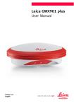
Leica GMX901 User All instructions required in order to operate
9
Manual
the product to a basic level are contained in
the User Manual. Provides an overview of the
product together with technical data and
safety directions.
9
Leica
GMX902 GG/
GMX902 GNSS
User Manual
All instructions required in order to operate
9
the product to a basic level are contained in
the User Manual. Provides an overview of the
product together with technical data and
safety directions.
9
Structural Monitoring Equipment
List
Describes items and setup of monitoring
systems.
9
GNSS Networks
and Reference
Stations Equipment List
Describes items and setup of permanent GNSS
reference stations.
9
Leica GNSS Spider
Online Help
Comprehensive guide to the GNSS Spider software. Included are context-sensitive descriptions of GNSS Spider software settings and
functions.
9
Installation Guide - Detailed installation instructions for the
Leica GNSS Spider installation of Leica GNSS Spider
Reference Station
9
Refer to the following resources for all GMX900 Series documentation/software:
• the Leica GMX900 CD
• https://myworld.leica-geosystems.com
GMX900 Series, Introduction
3
Table of Contents
In this manual
ChapterPage
1
GNSS Spider Configuration & Settings
1.1
1.2
1.3
1.4
1.5
1.6
1.7
1.8
2
GNSS Spider Status Information
2.1
2.2
2.3
4
Overview
1.1.1
Installation
1.1.2
Site Server
1.1.3
Site Server View
Site Configuration
1.2.1
Automatic Site Setup
1.2.2
Manual Site Setup
1.2.3
Connect/Disconnect Site
Site Settings
Instrument Settings
1.4.1
Elevation Mask
1.4.2
Raw data (GMX902 GG /GMX902 GNSS Only)
1.4.3
PPS (GMX902 GG /GMX902 GNSS Only)
Instrument Commands
RT Positioning Products
1.6.1
Create/Edit RT Positioning Products
1.6.2
Tips & Tricks
File Products
1.7.1
Create File Products
1.7.2
Tips & Tricks
PP Positioning Products
1.8.1
Create PP Positioning Products
1.8.2
Tips & Tricks
Site Map
Site Status
2.2.1
Sensor Tab
2.2.2
Tracking Tab
Raw Data Status
5
5
5
8
9
11
11
13
17
18
19
19
21
22
23
25
25
29
30
30
32
33
33
36
37
37
38
38
39
40
GMX900 Series, Table of Contents
1
GNSS Spider Configuration & Settings
1.1
Overview
Description
GMX901, GMX902 GG and GMX902 GNSS instruments are delivered with default
settings which cover the needs of the typical user. The settings can be adjusted
according to the customer needs and applications.
Requirements
GMX901:
GMX902 GG:
GMX902 GNSS:
Leica GNSS Spider v2.3.1 or later must have been installed.
Leica GNSS Spider v2.3.2 or later must have been installed.
Leica GNSS Spider v3.3 or later must have been installed.
Refer to "1.1.1 Installation"for information on how to start Leica GNSS Spider
at a basic level or refer to "Leica GNSS Spider Reference Station Installation
Guide" for advanced information.
1.1.1
Installation
Site Server installation
Use Site Server Installation option to install all GNSS Spider Site Server related
components including the local SQL database which, when populated, contains
all the information required to manage one or mulitple GNSS instruments. This
installation type installs all modules required for instrument control, raw data
archiving and position computation.
Site Server installation step-by-step
The Installation Guide Wizard is a tool that guides you through the GNSS Spider
installation routine.
Step
Description
1.
Start the GNSS Spider setup program.
2.
The InstallShield Wizard welcome dialog appears.
You can use Next > and < Back to navigate through the Wizard
steps.
GMX900 Series, GNSS Spider Configuration & Settings
5
Step
Description
3.
The Setup Type dialog appears. Select Site Server Installation. This
option installs a Spider site server. The site server is the component
that connects to instruments, controls and retrieves data from them.
Also the GUI client application will be installed. The GUI is the graphical user interface for the Spider server. For typical monitoring applications, the other servers listed in here are not required.
4.
5.
Click Next > to proceed.
6.
The Password dialog appears. Enter and confirm a unique password
that will be required by clients to access your Site Server.
)
7.
6
Depending on what is already installed on your computer, the installation wizard can ask you for a path to the Dongle driver and SQL
Server 2005 Express database installation files. These files are
included on your GMX900 CD.
We recommend that the Site Server password is different from your
user account and SQL system administrator passwords.
Click Next > and proceed until the InstallShield Wizard is completed.
GMX900 Series, GNSS Spider Configuration & Settings
Step
Description
8.
Select the check box to start the GNSS Spider client user interface
once installation is complete.
)
Refer to the Installation Guide - Leica GNSS Spider Reference Station for
detailed information on the individual settings.
GMX900 Series, GNSS Spider Configuration & Settings
7
1.1.2
Site Server
Site Server installation step-by-step
The Installation Guide Wizard is a tool that guides you through the GNSS Spider
installation routine.
Step
Description
1.
Connect the instrument to the computer.
2.
Start the GNSS Spider Client GUI.
3.
Click the Server Management icon in the List Bar.
4.
This screen appears:
5.
Highlight the desired server in the server management window. Typically select the Local Site Server.
6.
Right click the desired server in the report view window and select
Open.
)
Edit/Close a Server
8
- Indicates an active or open server connection.
Use the context menu to change server settings or to close a server.
GMX900 Series, GNSS Spider Configuration & Settings
1.1.3
Site Server View
Site Server main
view
After opening the Site Server, the main view is shown. Use the Site Server to:
• define permanent GNSS sites
• configure instrument parameters at the sites
• check site status
• configure products, for example RT Positioning Products
a
b
f
c
d
g
h
e
i
S_GMX902_01
Site Server tabs
a)
b)
c)
d)
e)
f)
g)
h)
i)
Menu bar
Toolbar
List bar
Tree view
Watch view
Report view
Tabbed view
Context menu
Status bar
Component
Description
Menu bar
The Menu bar lists all available commands. If the command
is greyed out, it is not applicable. The menu item between
Management and Tools is a dynamic. The menu item
shown is always relevant to the view that is currently
active.
Toolbar
Displays the commands used most often. Customise the
toolbar by adding and removing buttons.
List bar
A navigation tool to toggle access between a Server view,
management components or Site status views.
Tree View/
Report View
Select a component from the Menu Bar or List Bar to show
the management view. The typical management view
consists of a tree view in the left pane and a report view
in the right pane. The report view displays objects corresponding to the highlighted item in the tree view.
Watch view
A list of messages of actions or events taken by the GNSS
Spider server. The messages are triggered by the operator
or the server itself. The messages are logged in real-time.
The messages are colour coded to help distinguish critical
events.
Tabbed view
Use the tabs to switch from one view to another.
Context menu
Right click an item to open a context menu. The context
menu contains item-specific commands.
Status bar
The local time and your sever access level.
Use the Site Server tabs to switch from one view to another.
GMX900 Series, GNSS Spider Configuration & Settings
9
Site tab
Site Server tab
Description
Site Map
Gives you a graphical overview of the status and configuration of all sites belonging to your server.
Site
Create, edit, view and delete such sites.
Sensor
Configure instruments settings.
Raw Data Status
View the real-time connection status of the configured
sites.
File Products
Define the creation of data files, e.g. RINEX and event logs.
RT Products
Create real-time correction streams for RTK rovers.
RT Positioning
Create baselines for real-time positioning between two
sites.
PP Positioning
Create baselines for post processed positioning between
two sites.
•
•
•
•
Sensor tab
•
•
•
•
Site Server icons
A site is a GNSS instrument and antenna connected to a GNSS Spider server.
The Site tab enables you to create, edit, view and delete such sites. Once
you have created a site, you will be able to connect to and configure site
properties. Its status can be monitored and products such as Positioning
products can be defined. Additionally, the site properties report view allows
you to save, print and search its contents.
The tree view shows the different categories of site properties.
The report view shows the instrument status using icons.
A sensor is basically the instrument situated at the site.
The Sensor tab enables you to view and edit the instrument settings and
upload them to the instrument. The sensor report view allows you to save,
print and search its contents.
The tree view shows the different categories of site properties.
The report view shows the instrument status using icons. Refer to paragraph "Site Server icons".
Icons
Description
Site is disconnected from GNSS Spider
server.
Site is connected to the GNSS Spider
server.
Site is started. Only started sites are
taken into account for product generation.
Report view text in black: Current site
and instrument settings have been
uploaded to the instrument.
Report view text in blue: Current site
and instrument settings have not
been uploaded to the instrument.
10
GMX900 Series, GNSS Spider Configuration & Settings
1.2
Site configuration
step-by-step
Site Configuration
Step
Description
1.
Start the GNSS Spider Client GUI (Graphic User Interface)
2.
Open a server.
3.
A GMX901, GMX902 GG and GMX902 GNSS can be installed with the
Site Setup Wizard or manually. The Wizard will start automatically if
you open a server that has no defined sites.
No site configured:
Site configured:
↓
↓
Site Setup Wizard starts.
Refer to"1.2.1 Automatic Site
Setup".
The Site tab opens.
Refer to "1.2.2 Manual Site
Setup".
1.2.1
Automatic Site Setup
Description
The Site Setup Wizard is a tool that guide you through the following stages of
a site configuration:
• Setting up communication to the GMX901/GMX902 GG/GMX902 GNSS
• Site location information
• Configuration of instrument operation parameters
Automatic Site
Setup step-by-step
Step
Description
1.
Open a server.
2.
Select Tools from the Menu Bar.
3.
From the drop-down menu select
sponding toolbar button.
Wizard... or select the corre-
4.
The Wizard Welcome dialog appears. Use Next > and < Back to navigate through the Wizard steps.
5.
The Sensor Communication dialog appears.
Select:
• Sensor: GMX901 or GMX902
• Sensor connected via: Select the type of communication
from the drop-down list
GMX901: The default serial port settings are
115200/None/8/1/None.
GMX902 GG/GMX902 GNSS: The default serial port settings are
115200/None/8/1/None.
Refer to "1.4 Instrument Settings"for how to change GMX900 Series
serial port settings from within GNSS Spider.
6.
Click Next> to connect the sensor and proceed.
GMX900 Series, GNSS Spider Configuration & Settings
11
Step
)
)
12
Description
If GNSS Spider fails to connect the sensor, the Sensor Connection
Failure dialog appears.
7.
The General site parameters dialog appears.
Enter the
• site name
• the site code, which is a unique 4 character ID
• marker information. The marker information is used in the RINEX
headers. Typically, it corresponds to Site name and code.
8.
Click Next> to proceed.
9.
The Antenna dialog appears.
Enter the
• accurate coordinates.
• correct antenna type and height reading.
10.
The Receiver type dialog appears.
Enter the
• serial number of the instrument.
11.
Click Next> and proceed until the Site Setup Wizard is completed.
If the connection to the instrument is not yet possible, the Site Setup Wizard
can still be used. In that case, finish the Wizard despite the failed connection,
but remember to upload the settings once the connection can be established.
Refer to the GNSS Spider Online Help for detailed information on the individual
settings.
GMX900 Series, GNSS Spider Configuration & Settings
1.2.2
Manual Site Setup
Manual Site Setup
step-by-step
For standard setups, it is recommended to run through these basic configuration steps. Refer to the GNSS Spider Online Help for detailed information on the
individual settings.
Step
Description
1.
Open a server.
2.
Switch with the Tabbed view to the Site tab.
3.
Right click in the report view and select New... from the context
menu.
4.
This dialog appears:
GMX900 Series, GNSS Spider Configuration & Settings
13
Step
Description
5.
Select Sensor comm 1 or Sensor comm 2 tab:
• Select the sensor type GMX901 or GMX902 and the communication parameters.
• Select the streaming data rate.
)
14
The maximum data rate for the GMX901 is 1Hz.
GMX900 Series, GNSS Spider Configuration & Settings
Step
Description
6.
Select the General tab:
•
•
•
Enter a site name, a unique 4 character ID and marker information. Marker information is used for the RINEX header only.
Enable Provide original raw data if you want to share a data
stream with another GNSS Spider site server.
Enable Used for global products for convenience when making
products. This action allows you to define a single product that is
used for all sites.
GMX900 Series, GNSS Spider Configuration & Settings
15
Step
Description
7.
Select the Antenna tab:
•
•
•
16
Enter accurate coordinates. From the View menu, select
Settings to change from cartesian to geodetic coordinates.
The Geoid separation will be added to NMEA GGA strings
created by positioning products. Use the default if in doubt.
Enter the correct Antenna type and Height reading.
8.
Press OK to confirm or Cancel to end the function.
9.
Connect the instrument. For more details refer to "1.2.3
Connect/Disconnect Site".
GMX900 Series, GNSS Spider Configuration & Settings
1.2.3
Connect/Disconnect Site
Connect
Connect establishes a connection between the GNSS Spider server and the
selected site (instrument) via the defined communication method, either serial,
modem or TCP/IP connection. This command is not active in case a connection
is already established. After the connection is established, you are able to
upload settings.
)
Disconnect
)
Connect/Disconnect an instrument
step-by-step
)
To prevent accidental change of communication settings it is not possible to
edit these settings for a connected instrument.
Disconnect terminates the connection between the PC and the instrument. This
command can be selected if the instrument is connected.
For all real-time products, or for creating RINEX files from a raw data stream,
the instrument must stay connected at all times.
Step
Description
1.
Open a server.
2.
Switch with Tabbed view to either the Site, Sensor or Raw Data
Status tab.
3.
Right-click on a site (instrument) in the Report view on the right-hand
side.
4.
Select Connect or Disconnect in the Context menu to establish
communication.
5.
GNSS Spider will indicate the successful connection or termination
with a progress bar and watch view message.
For further information on troubleshooting communication problems refer to
the GNSS Spider Online Help.
GMX900 Series, GNSS Spider Configuration & Settings
17
1.3
Site Settings
Description
Several site settings can be adjusted according to your needs. The most important are:
• Site name
• Coordinates
• Antenna settings
• Communication parameters
Edit a site step-bystep
Step
Description
1.
Open a server.
2.
Switch with Tabbed view to either the Site, Sensor or Raw Data
Status tab.
3.
Double-click a site or right-click and select Properties... in the
Report view.
4.
Make your changes.
5.
Press OK to confirm or Cancel to end the function.
6.
Right-click on the site and select Upload settings from the Context
menu.
)
)
18
The Site name will change from blue to black when the settings are
uploaded.
The GNSS Sensor comm settings of a connected site cannot be edited.
GMX900 Series, GNSS Spider Configuration & Settings
1.4
Instrument Settings
Description
The following instrument settings can be adjusted according to your needs with
GNSS Spider:
• Elevation mask
• Raw data (GMX902 GG/GMX902 GNSS only)
• Pulse Per Second (PPS) (GMX902 GG/GMX902 GNSS only)
Modify instrument
settings step-bystep
Step
Description
1.
Open a server.
2.
Switch with the Tabbed view to the Sensor tab.
3.
On the right-hand side the Sensor Properties view is shown. The
current instrument settings are displayed.
4.
In the tree view, select the category you want to edit (e.g. General).
5.
Right-click on a site in the report view and select Properties from the
Context menu.
6.
Make your changes:
• Settings relating to the elevation mask. Refer to "1.4.1 Elevation
Mask".
• Settings relating to the raw data. Refer to "1.4.2 Raw data
(GMX902 GG/GMX902 GNSS Only)".
• Settings relating to the PPS. Refer to "1.4.3 PPS (GMX902
GG/GMX902 GNSS Only)".
7.
Press OK to confirm or Cancel to end the function.
8.
Right-click on the site and select Upload settings from the Context
menu.
1.4.1
Elevation Mask
Description
The elevation mask is the elevation below which satellite data will not be
recorded. Satellites below this elevation will not be tracked.
Edit elevation mask
step-by-step
Step
Description
1.
Open a server.
2.
Switch with Tabbed view to the Sensor tab.
3.
In the tree view, select the General category.
4.
Right-click on a site in the report view and select Properties from the
Context menu.
GMX900 Series, GNSS Spider Configuration & Settings
19
)
20
Step
Description
5.
Edit the Elevation mask.
Low satellites are important for a good geometry, but they also have a noisier
signal. If in doubt use the default setting 10°.
GMX900 Series, GNSS Spider Configuration & Settings
1.4.2
Raw data (GMX902 GG/GMX902 GNSS Only)
Description
The raw data interface allows you to configure a raw data output over port P2
for the GMX902 GG/GMX902 GNSS. Use this functionality when you want to
provide raw data to another application, such as a second GNSS Spider site
server.
Edit raw data
settings step-bystep
)
Step
Description
1.
Open a server.
2.
Switch with Tabbed view to the Sensor tab.
3.
In the tree view, select the Raw data category.
4.
Right-click on a site in the report view and select Properties from the
Context menu.
5.
Edit the Raw data (LB2) settings.
•
•
If you want to configure a site in GNSS Spider receiving such a raw data
stream, set Passive LB2 as sensor type.
The raw data interface is typically not required to stream raw data to GNSS
Spider over the main sensor communication line. See setting of Streaming
data rate in the Sensor Comm settings for that.
GMX900 Series, GNSS Spider Configuration & Settings
21
1.4.3
PPS (GMX902 GG/GMX902 GNSS Only)
Description
PPS stands for Pulse Per Second. It is a pulse that is output at a specified
interval time over the PPS port of the GMX902 GG/GMX902 GNSS. Use this
functionality to activate or synchronise another device, such as accelerometers.
Edit PPS settings
step-by-step
)
Step
Description
1.
Open a server.
2.
Switch with Tabbed view to the Sensor tab.
3.
In the tree view, select the PPS category.
4.
Right-click on a site in the report view and select Properties from the
Context menu.
5.
Edit the PPS settings.
•
•
22
Both the raw data and the PPS interface will not be immediately active on
pressing OK. Select Upload settings from the Context menu to activate
the interface.
The sensor properties, Logging, Real-time 1, Real-time 2 and External
sensors are not supported by the GMX902 GG/GMX902 GNSS.
GMX900 Series, GNSS Spider Configuration & Settings
1.5
Instrument Commands
Description
The instrument commands are available in a context menu. Select a site on the
Site or Sensor tab and right-click. A menu with all available commands will pop
up.
Context menu
Connect/Disconnect
After the connection is established, you are able to upload settings or start
logging. For additional information refer to "1.2.3 Connect/Disconnect Site"
)
To prevent the accidental change of communication settings, you are not able
to edit the settings for a connected instrument!
Upload
)
Start
)
The upload saves configuration data to the instrument and stops current
product creation.
The Upload settings command can only be selected if the instrument is
connected. If Upload settings is sent to a instrument that is started, product
creation will be stopped.
For GMX901, GMX902 GG and GMX902 GNSS instruments, Start tells GNSS
Spider to begin with product creation for this site. For GRX1200+ Series instruments, Start can trigger more advanced functions. See the GNSS Spider Online
Help fordetails.
The Start command can only be selected if the instrument is connected but not
started.
GMX900 Series, GNSS Spider Configuration & Settings
23
Remote port
settings
24
Allows you to change the parameters of the GMX901, GMX902 GG and GMX902
GNSS serial port to which you are currently connected remotely. For serial channels, it also automatically adjusts the GNSS Spider server's serial port to match
the new setting. Use with care when connected over TCP/IP and a Serial-to-IP
converter. For this case, you will also need to change the serial port settings of
the converter manually.
GMX900 Series, GNSS Spider Configuration & Settings
1.6
RT Positioning Products
Description
Positions are the most important output of a monitoring system. In the GNSS
Spider site server, it is possible to compute and distribute real-time position
data streams for attached sites. One such data stream is called an RT Positioning Product. The positions are calculated as baselines using one site as a
reference and another site as the rover. The output can be in NMEA GGA, GGQ
and LLQ format (intended to be used by other software applications, such as
Leica GNSS QC) or directly to Leica GeoMoS monitoring software.
)
1.6.1
Create an RT Positioning Product
step-by-step
Whilst high accuracy positions can be computed in real-time with single
frequency data, the reliability is much lower than with dual frequency data. For
this reason, it is recommended to use the GMX902 GG or GMX902 GNSS rather
than the GMX901 for real-time monitoring applications.
Create/Edit RT Positioning Products
Step
Description
1.
Open a server.
2.
Switch with the Tabbed view to the RT Positioning tab.
3.
Right-click in the RT Positioning report view and select New... from
the context menu.
GMX900 Series, GNSS Spider Configuration & Settings
25
26
Step
Description
4.
Select the General tab:
• Each RT Positioning product must have a unique name.
• The rover site and reference site must be different sites. Zero
baselines based on identical data streams are not permitted.
• The rover site and reference site must be off the same type (real
or simulated).
• Select the real-time output settings.
• GMX901: Only L1 processing is possible. GPS only is supported.
GMX902 GG/GMX902 GNSS: L1/L2 processing is recommended.
GPS & GLONASS are supported.
GMX900 Series, GNSS Spider Configuration & Settings
Step
Description
5.
Select the Channel tab:
• Enter the settings for the configured real-time output.
6.
Select the Logging tab:
• Choose a path to the log the real-time output files (if desired).
)
It is the user responsibility to ensure that the hard disk does not fill.
GMX900 Series, GNSS Spider Configuration & Settings
27
Active and Inactive
products
Step
Description
7.
Select the Rates tab:
• Enter the position output rate. If the output rate is slower than
the input rate, the position calculation is done at either 1 Hz or
the input rate (whichever is faster) and sampled.
• The raw data input rate must be at least as fast as the position
output rate.
8.
For more detailed information on RT Positioning products refer to the
GNSS Spider online help or press F1 to open context-sensitive help
for each dialog.
9.
Press OK to confirm or Cancel to end the function.
10.
The RT Positioning Products will immediately become active after
they have been created, as long as the configured sites are
connected and started.
The status of the product is shown by an icon:
•
Active products
are created as long as the configured sites are
connected and started.
•
Inactive products
are not created, but are available for later activation.
Change the status of a product by checking or unchecking Active in the
product's context menu.
Edit RT Positioning
Products
28
To edit a RT Positioning Product it is necessary to deactivate it first.
GMX900 Series, GNSS Spider Configuration & Settings
1.6.2
Tips & Tricks
Important notes
•
•
•
•
•
•
Positions with
sites from multiple
site servers
RT Positioning
products are just
like RTK on the
rover
•
•
•
•
•
•
Ambiguity resolution techniques
•
•
•
•
•
Elevation Mask
•
•
For a Positioning Product to function, both sites must be connected and
started.
Check the Raw Data Status to make sure that the status is Receiving data.
If no data is received from the rover station, no position will be calculated.
A null NMEA string will be output.
If no reference data is available, a navigated position will be calculated .
Relative latency will affect the accuracy of the results. The latency is
shown in the Raw Data Status tab.
If a single frequency site (GMX901) is selected for the processing and the
processing is set to "L1/L2" then no position will be calculated.
Create an Original Raw Data RT Positioning product for the site on the
remote site server. Enable Provide original raw data in the site properties.
Create a Passive (LB2) site on the local site server.
Reliability of ambiguity resolution will decrease with the baseline length.
The product can take a long time to fix, it cannot fix at all or it can incorrectly fix for long baselines.
Accuracy will also decrease with the baseline length.
User will be warned when creating a baseline longer than 30 km but there
is no limit on the baseline length.
The Leica RTK kernel is tuned for Leica data and best results will be obtained
when using Leica instruments.
Three ambiguity resolution options are available:
– On Known Point (default)
– While Moving (also known as OTF or on-the-fly)
– Quasi Static
The Moving ambiguity resolution technique is suitable for instruments
with high dynamics. Use for sites that are expected to move rapidly or far
from their initial position. The reliability is not as high as with the other
approaches.
On Known Point ambiguity resolution, is more reliable but requires that
the reference station and rover station have highly accurate coordinates. If
the sites are moving then the coordinates must be updated in the site
configuration because inaccurate coordinates will prevent GNSS Spider
from resolving the ambiguities.
Quasi Static is a combination of the While Moving and On Known Point
approaches. The site coordinates are used to aid the ambiguity resolution.
They do not need to be accurately known (a few decimetres or a metre is
sufficient). Use for sites that are expected to move but not far or fast.
Wrong fixes are more likely with While Moving initialisation, especially for
long baselines. A wrong ambiguity fix will be seen as a jump in the coordinates.
All data from the data streams are used by the RT Positioning products.
Using data below 10° can cause lower accuracy positions.
GMX900 Series, GNSS Spider Configuration & Settings
29
1.7
File Products
Description
In GNSS Spider, the template that describes how the RINEX data downloaded
from the instrument can be handled, is called a File Product.
A Global File product is referred to as a single file product configuration that
is used for multiple sites. A Global File product allows a single configuration for
a RINEX product which can be used for all sites connected to the site server. The
Global File product ensures that the files for all sites are created based on the
same configuration.
1.7.1
Create File Products
Create a File
Product step-bystep
30
Step
Description
1.
Open a server.
2.
Switch with the Tabbed view to the File Product tab.
3.
Right-click in the File Product report view and select New... from the
context menu.
4.
Select the General tab:
• Enter a unique Product name.
• Select the Site name and code for which you want to generate
a product.
• Select the Product type, RINEX.
GMX900 Series, GNSS Spider Configuration & Settings
Step
Description
5.
Select the Contents tab:
• Specify the contents of the RINEX files.
• Set Product dynamics to Static.
6.
Select the FTP tab to specify an FTP push and its target location. The
FTP push will include all files that are defined for this product.
7.
Select the Advanced tab to enter and run a command-line operation
after product creation.
8.
Press OK to confirm or Cancel to end the function.
9.
The File Product will immediately become active after its creation, as
long as the configured sites are connected and started.
GMX900 Series, GNSS Spider Configuration & Settings
31
1.7.2
Tips & Tricks
Important notes
•
•
32
All sites that will use a Global File product, must have the Use for Global
File products check box checked.
When activating a File product make sure that the site is started.
GMX900 Series, GNSS Spider Configuration & Settings
1.8
PP Positioning Products
Description
PP Positioning products are GNSS baselines that are computed using logged
RINEX file products. PP Positioning products enable accurate position computation also in difficult GNSS environments. Difficult environments can be caused
for example by severe obstructions, where real-time processing can fail or gives
unsatisfying results.
1.8.1
Create PP Positioning Products
Create a File
Product step-bystep
Step
Description
1.
Open a server.
2.
Switch with the Tabbed view to the PP Positioning tab.
3.
Right-click in the PP Positioning report view and select New... from
the context menu.
4.
Select the General tab:
• Enter a unique Product name.
• Site name and code: Select the name of the monitoring site.
• Site File Product: Select the RINEX File Product that is activated
for the monitoring site.
• Reference site: Select the name of the reference site. The
monitoring and reference site must be different sites (zero baselines are not permitted). The monitoring and reference site must
be of the same type (real or simulated).
• Reference File Product: Select the RINEX File Product that it
activated for the reference site. The monitoring and reference
site File Product must be of the same length.
• If the Dynamics is set as Kinematic, a position will be computed
for every epoch and output to the log file. Only an average value
will be stored in the database. If the Dynamics is set as Static,
a single position will be computed for the whole session.
GMX900 Series, GNSS Spider Configuration & Settings
33
34
Step
Description
5.
Select the Logging tab:
• If desired, choose a path is log the files
6.
Select the Processing tab:
• Select the Satellite system. The GMX901 is a GPS only instrument, so the satellite system GPS only can be selected. For
GMX902 GG/GMX902 GNSS, select GPS/GLONASS.
• Frequency: Select the frequency of the data to be processed. If
L1/L2 is selected and the RINEX files contain L1 only data, no
position will be calculated.
• The same processing parameters are used as the defaults in
LEICA Geo Office.
7.
For more detailed information on PP Positioning products refer to the
GNSS Spider online help or press F1 to open context-sensitive help
for each dialog.
8.
Press OK to confirm or Cancel to end the function.
GMX900 Series, GNSS Spider Configuration & Settings
Step
Description
9.
The PP Positioning product will immediately become active after it's
created.
GMX900 Series, GNSS Spider Configuration & Settings
35
1.8.2
Tips & Tricks
Important notes
•
•
•
•
•
36
For a PP Positioning product to function, both sites must be connected and
started and the File Products must be activated.
File Products of at least 10 minutes must be used if processing L1 only data.
If the File Products are split (because a site is disconnected and reconnected) then only the first one will be processed.
Post Processing will potentially use a large amount of CPU and hard disk.
Therefore. the Post Processing is done sequentially (one at a time) and only
once creation of all file products has finished.
Currently only uncompressed file products and file products compressed by
Zip and GZip are supported.
GMX900 Series, GNSS Spider Configuration & Settings
2
GNSS Spider Status Information
2.1
Site Map
Description
The site map gives you a graphical overview of the status and configuration of
all the sites from your server.
Graphical Settings
Right-click in the background and you can open the Graphical settings...
dialog, or alternatively select Graphical Settings... from the Site Map menu.
This dialog explains all symbols and allows you to switch them on or off.
Zoom
The Site Map menu allows you also to access the Zoom In, Zoom Out and
Zoom 100% functions.
GMX900 Series, GNSS Spider Status Information
37
2.2
Site Status
Description
The Site status views are used to check the logging and tracking status of each
site or instrument. The List bars lists all sites configured sites on the Site Server.
Use the site icons to switch between sites.
The report view consists of two tabs:
• Sensor: Displays information for site, instrument and satellites.
• Tracking: displays status information about currently tracked satellites.
The status icons are only updated while the Site Server is connected to the
instrument.
2.2.1
Sensor Tab
Description
Select the Sensor tab to view instrument status information updates.
38
GMX900 Series, GNSS Spider Status Information
2.2.2
Tracking Tab
Description
Select the Tracking tab to view information on satellites currently tracked
along with a sky plot.
)
For further information on the Tracking tab refer to the GNSS Spider Online
Help.
GMX900 Series, GNSS Spider Status Information
39
2.3
Raw Data Status
Description
Raw Data Status tab report view displays real-time information on the current
data stream and an overview of the communication activity.
Site Server icons
The icons are updated once a minute and every time you connect to, upload to
or start the instrument. The master time site is highlighted in yellow.
Icons
Description
GNSS Spider server is disconnected from the instrument.
GNSS Spider server is connected to the instrument.
Logging is active on the instrument.
Communication
Activity
40
The Comm Activity (Communication activity) field in the report view list the
current communication status between the instrument and GNSS Spider. Colour
coding of the text is used to enable quick analysis of the communication status.
Status
Description
disconnected
Site is not connected (colour grey).
receiver status
Data is streamed but not enough data has been received
for the site to be usable (colour orange).
receive data
Site is connected and data stream is received (colour
black).
downloading
Shown during automatic file download (colour black). For
Leica GPS1200 instruments only.
uploading
Shown during firmware file upload or settings upload
(colour black).
connecting
The site is currently trying to connect to the data stream
but is not able to establish a connection. Check your
communication line or your communication settings
(colour red).
no response
The site is connected but no response is received at all
within standard time outs (colour red).
GMX900 Series, GNSS Spider Status Information
Master Time Site
•
•
Too accurately compute the data latency it is necessary to align the
computer clock closely with GPS time. To help this one site must be defined
as the Master site.
Chose the site with the most reliable communication link as the Master site.
Active connections to Leica instruments are preferable over other instrument types. In the Raw Data Status view, the line of the master time site is
highlighted in yellow.
GMX900 Series, GNSS Spider Status Information
41
standard 14001).
Ask your local Leica Geosystems dealer for more information about
our TQM program.
Leica Geosystems AG
Heinrich-Wild-Strasse
CH-9435 Heerbrugg
Switzerland
Phone +41 71 727 31 31
www.leica-geosystems.com
Original text
Printed in Switzerland
© 2009 Leica Geosystems AG, Heerbrugg, Switzerland
Leica Geosystems AG, Heerbrugg, Switzerland, has been certified as being equipped
with a quality system which meets the International Standards of Quality Management
and Quality Systems (ISO standard 9001) and
Environmental Management Systems (ISO
751991-1.3.0en
Total Quality Management: Our commitment to total customer
satisfaction.