1
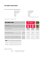
Geodetic Monitoring System
Equipment List
2
Overview
GeoMoS Modules
1.1 GeoMoS Monitor (758 749) .......................................................................................................... 6
1.1.1 GeoMoS Monitor Option 1 (758 751) ..........................................................................................6
1.1.2 GeoMoS Monitor Option 2 (758 752) ..........................................................................................6
1.2 Sensor License (758 750) ............................................................................................................. 7
1.3 GeoMoS Analyzer (723 366) ......................................................................................................... 7
1.3.2 GeoMoS Analyzer Option 1 (758 753) .........................................................................................8
1.4 GeoMoS Demo (724 933) ............................................................................................................. 8
GeoMoS Maintenance
2.1 Customer Care Packages (CCP)...................................................................................................... 9
2.2 Other Services .............................................................................................................................. 9
Monitoring Systems
3.1 Overview .................................................................................................................................... 10
3.2 Setup of a Total Station with direct serial ................................................................................... 12
3.3 Remote Setup of a Total Station with Radio (GFU-14) ................................................................. 13
3.4 Remote Setup of a Total Station with Radio (TCPS27) ................................................................. 15
3.5 Setup of a MC75......................................................................................................................... 16
3.6 Setup of real-time GPS with GMX902 Sensors ............................................................................. 17
3.7 Setup of post processing GPS with GRX1200Pro Sensors............................................................. 19
3.8 Setup of a Meteo Sensor ............................................................................................................ 21
3.9 Setup of a Level.......................................................................................................................... 22
3.10 Setup of a GMX902 Sensor with Radio (GFU-14) ....................................................................... 23
3.11 Setup of a GPS Sensor co-located with a Total Station .............................................................. 25
Sensors
4.1 TPS Sensors................................................................................................................................ 27
4.1.1 Supported Sensors ...................................................................................................................27
4.1.2 Supported Reflectors ................................................................................................................27
4.1.3 Tribrachs ..................................................................................................................................28
4.1.4 Other TPS Accessories ..............................................................................................................28
4.2 GPS Sensors ............................................................................................................................... 29
4.2.1 Supported Sensors ...................................................................................................................29
4.2.2 Antennas..................................................................................................................................29
4.2.3 GPS Accessories........................................................................................................................30
4.2.4 GPS Spider................................................................................................................................31
4.2.5 GNSS QC...................................................................................................................................31
4.3 Levels......................................................................................................................................... 32
4.3.1 Supported Sensors ...................................................................................................................32
4.3.2 DNA Staffs ...............................................................................................................................32
4.3.3 Sprinter Staffs ..........................................................................................................................32
3
4.4 Other Sensors ............................................................................................................................ 33
4.4.1 Inclination Sensors ...................................................................................................................33
4.4.2 Meteo Sensors .........................................................................................................................33
Power supply
5.1 Continuous 12V Power supply for GPS1200 and NIVEL sensors .................................................... 34
5.2 Continuous 12V Power supply for TPS sensors ............................................................................ 34
Cables
6.1
6.2
6.3
6.4
Power Cables.............................................................................................................................. 35
Communication Cables................................................................................................................ 35
Communication / power cable between Nivel210 sensors and GPS1200 ...................................... 35
Antenna cables........................................................................................................................... 35
For transmitting data
7.1 Satelline Radio Modem, Radio Antennas and Accessories ............................................................ 36
7.2 TCPS27 Radio Modem and Accessories........................................................................................ 36
7.3 Mobile Phones and Accessories................................................................................................... 37
Accessories
8.1 Switchbox................................................................................................................................... 38
4
GeoMoS Modules
GeoMoS - Geodetic Monitoring System Applications:
Landslide monitoring
Dangerous slopes
Open pit mines
Settlement Areas
Dams
Volcanoes
Dams
Bridges
High rise buildings
Historical buildings
Large structures
Foundations
Roads
Airports
Tunnels
Ski lifts
…and all required Automatic Surveys
GeoMoS comprises the following modules:
Article Number (SAP)
GeoMoS
Demo
Article Name
GeoMoS
Analyzer
User Versions
GeoMoS
Monitor
LEICA GeoMoS Versions
Demo
Version
(1 year)
758 749
723 366
724 933
CD-ROM included
723 367
z
z
z
USB Dongle (default)
734 713
z
z
z
Parallel Dongle (optional)
734 712
}
}
}
Sensor License
758 750
}
─
z
Monitor Option 1 (TPS computation)
758 751
}
─
z
Monitor Option 2 (Limit checks and Messaging)
758 752
}
─
z
Analyzer Option 1 (TPS Post-Processing)
758 753
─
}
z
Legend
z
included: automatically, not removable
}
optional
─
not available
Software protection keys
734 712
734 713
Software protection key (parallel)
Software protection key (USB)
5
1.1 GeoMoS Monitor (758 749)
Leica GeoMoS makes use of the Microsoft SQL database. With Leica GeoMoS the free version Microsoft SQL Server 2005 Express
is provided and will be installed, if no SQL server is available.
Connection to sensors (serial or TCP/IP) with valid Sensor Licenses
Project management
User levels
Learn points
Manual stand point coordinate determination with Free Station, Distance Intersection or
GPS Update
Automatic measurements with various options
Blunder tolerance checks on raw data
Information about the current system and measurement status
Calculation of GPS displacements and daily average results
Automatic database export
SQL Server 2005 Express database included
GeoMoS Monitor is the monitoring software for the normal use of the customer. The customer can collect and store data.
Additional options can be added later.
A number of options are available for use together with GeoMoS Monitor:
758 751
758 752
GeoMoS Monitor Option 1 (TPS computation)
GeoMoS Monitor Option 2 (Limit checks and Messaging)
Note: Sensors can only connected to GeoMoS Monitor, if the required amount of sensor licenses has been ordered
also. Refer to the section “1.2 Sensor License” for more detail.
1.1.1 GeoMoS Monitor Option 1 (758 751)
TPS computation
Automatic total station stand point setup with different methods (Free Station,
Distance Intersection or GPS Update)
Calculation of any total station results including coordinates, displacements, profiles,
distance reduction
Calculation of any total station correction with Free Station, Distance Intersection,
Orientation, PPM and Vz Correction groups
Calculation of daily average results for total stations
1.1.2 GeoMoS Monitor Option 2 (758 752)
Limit checks and Messaging
6
Automatic computation of limit checks
Multiple levels of limit checks (yellow, orange, red)
Limit Level 1, 2 and 3 can be assigned independent actions
Four different types of limit check computation (absolute, short time, long time and
regression)
Allows emails and SMS to be sent, applications to be run, the database to be queried
and digital outputs to be set when defined messages are generated by the system
1.2 Sensor License (758 750)
The sensor license concept means that the software scales with the number and type of sensors you have connected. Additional
sensor licenses can easily be added later should your needs change.
For each sensor you need to order a special amount of Sensor Licenses (Art. No. 758 750). The required amount of sensor
licenses per sensor is listed below:
Amount
required per
sensor
* Sensor License
TPS Sensor
30
GPS Sensor
10
Connection to a GPS Spider Site Server with all
Spider Positioning Products
Connection to a GPS Spider Site Server with all
Spider Post Processing Products
10
10
Nivel200 Sensor
3
Digital Level
3
Temperature / Pressure Sensor
1
Note that each sensor requires sensor licenses even though the sensor is connected with a bus system to GeoMoS.
For more information about connectable sensors offering with GeoMoS Monitor please contact your local Leica Geosystems
organization or distribution partner.
1.3 GeoMoS Analyzer (723 366)
Leica GeoMoS makes use of the Microsoft SQL database. With Leica GeoMoS the free version Microsoft SQL Server 2005 Express
is provided and will be installed, if no SQL server is available.
Graphical and numerical visualization of results
More than one installation of Analyzer may access the data and do analysis
simultaneously
Project management
User levels
Outlier detection algorithm
Set results invalid/valid
Enter comments
Customizable graphics
Customizable reports with filter and search mechanism
Manual database import and export
Export to other systems e.g. ASCII, DXF and BMP
SQL Server 2005 Express database included
For online analysis using GeoMoS Analyzer at a remote location there needs to be continual connection between GeoMoS
Monitor and GeoMoS Analyzer computers.
A number of options are available for use together with GeoMoS Monitor:
758 753
GeoMoS Analyzer Option 1 (TPS Post-Processing)
7
1.3.2 GeoMoS Analyzer Option 1 (758 753)
Re-processing of the coordinate system, distance reduction, meteo model and all values
modified in the Data Editor
Data Editor to modify additive constants, reflector heights, temperature and pressure
Re-processing of the profile directions, instrument height and null coordinate together
with GeoMoS Monitor
1.4 GeoMoS Demo (724 933)
Note: GeoMoS Demo is only for demonstration purposes to sell the product. GeoMoS Demo is not for commercial sale. GeoMoS
Demo has the same functionality as GeoMoS Monitor and GeoMoS Analyzer but cannot be used for permanent monitoring
(automatic measurement will only run for a limited time).
8
GeoMoS Maintenance
2.1 Customer Care Packages (CCP)
A powerful and competent worldwide service and support network backs up LEICA GeoMoS. Customer Care Packages (CCPs)
provide you access to a world-class support & service infrastructure and ensure your systems are being kept up to date.
A wide selection of comprehensive Customer Care Packages is available bundling Hardware
Maintenance, Software Maintenance, Customer Support and Extended Warranty. For more information
about the CCP offering in your country please contact your local Leica Geosystems organization or
distribution partner.
The Customer Care Packages articles are available worldwide and can be ordered for end-users together with new software.
Select CCP
6000933
6000934
6000935
1 year GeoMoS Basic CCP
2 year GeoMoS Basic CCP
3 year GeoMoS Basic CCP
Select CCP for Distribution Partner
6000936
6000937
6000938
1 year GeoMoS Distr. Basic CCP
2 year GeoMoS Distr. Basic CCP
3 year GeoMoS Distr. Basic CCP
2.2 Other Services
The following services are available on request at daily rates.
Training at customer site
Installation support
Customizing
Information on article numbers are available on request.
9
Monitoring systems
3.1 Overview
Each monitoring project has specific measurement and accuracy requirements. If you are going to prepare a monitoring project
or plan to offer a quotation for a monitoring tender, the following five sections have to considered:
1. Sensors
TPS Sensors, prisms and mounting
GPS Sensors, antennas and mounting
Inclination Sensors, shelters and mounting
Meteo Sensors, mounting
Other Sensors
2. PC and Software
Robust PC with serial ports and GeoMoS, GPS Spider or GNSS QC.
3. Power
Reliable power source with backup
direct power or
separate units or
solar panels
4. Communication
Cables, radio modems
5. Miscellaneous
Measurement hut to protect the total station and PC from the elements for example
rain, sun, dust, snow
Pillars and monumentation
Climate control system (avoid temperature expansion, moisture, condensation and
uneven heating of the instrument)
Security
Access (physical and remote)
Combine Leica software, geodetic, geotechnical and meteorological sensors to match the needs of your monitoring challenge.
Basic examples are given in the next section to provide an idea of monitoring setups and options.
3.2 Setup of a Total Station with direct serial....................................................................................................................12
3.3 Remote Setup of a Total Station with Radio (GFU-14).................................................................................................13
3.4 Remote Setup of a Total Station with Radio (TCPS27).................................................................................................15
3.5 Setup of a MC75..........................................................................................................................................................16
3.6 Setup of real-time GPS with GMX902 Sensors .............................................................................................................17
3.7 Setup of post processing GPS with GRX1200Pro Sensors ............................................................................................19
3.8 Setup of a Meteo Sensor.............................................................................................................................................21
3.9 Setup of a Level ..........................................................................................................................................................22
3.10 Setup of a GMX902 Sensor with Radio (GFU-14) .......................................................................................................23
3.11 Setup of a GPS Sensor co-located with a Total Station..............................................................................................25
10
GeoMoS is an integrated solution that supports total station, GPS, levels and geotechnical sensors for an overall understanding
of structural movements.
In large monitoring projects total stations and GPS receivers can be combined in many different ways to match the requirements
and use a stable reference. The diagram below shows various possibilities.
Legend
▲
Stable reference point
●
Unstable monitoring point
Δ H, Δ X, Δ Y
Offsets to be set in GeoMoS
Total station with co-located GPS sensor
A GPS antenna can be mounted on the top of the measurement hut and applied to the total station stand point with a
three-dimensional offset.
To orientate the system, a GPS antenna inside the unstable area is used to update the reference point.
The GPS antenna needs a reference station so that baselines can be computed.
Reference points with co-located GPS sensors
A total station stand point can be measured and calculated with a free station or distance intersection to reference
points inside the unstable area.
A GPS antenna can be mounted on the top of the prism and applied to the point with a height offset.
The GPS antenna needs a reference station so that baselines can be computed.
Reference station
A GPS antenna can be mounted in a stable area as a reference station. The reference station should be as close as
possible (<3km) to the monitoring area so that the baselines can be computed with the highest accuracy.
11
3.2 Setup of a Total Station with direct serial
734 698
744 793
749 279
439 038
664 662
744 793
734 698
TPS Sensor (TCA 2003)
Switchbox with cable 2.0m for TPS/1000/ 1100/1200 and GeoMoS. Supports cold boot for TPS (important 24/7
hours/day monitoring)
GEV187, Y-cable, connects TPS to PC (9-pin RS232 serial) and external battery, 2.0m.
Select Power
439 038
749 279
GEV71, 4m car battery cable, connects TPS or GPS receiver to 12V car battery.
GEV208, Power supply unit for TPS 2003, for indoor use only, input 100V-240VAC 50-60HZ, output 12VCD, cable
with 5-pin Lemo to connect to TPS.
Standard mains/line cable select from the following list.
Select power cords for 12V power supply unit 749 279:
731
731
734
734
738
12
722
773
232
233
586
Power
Power
Power
Power
Power
Cord,
Cord,
Cord,
Cord,
Cord,
US-Version.
EU-Version.
UK-Version.
AUS-Version.
CH-Version.
3.3 Remote Setup of a Total Station with Radio (GFU14)
639 964
667 237
733
738
738
738
733 297
639 964
667 237
275, 733 276,
272, 738 273,
274, 738 275,
276
733
738
738
738
733 297
275, 733 276,
272, 738 273,
274, 738 275,
276
734 698
439 038
RS232 Reverser
749 279
439 038
439 038
749 279
744 793
749 279
664 662
744 793
734 698
733 297
TPS Sensor (TCA 2003)
Switchbox with cable 2.0m for TPS/1000/ 1100/1200 and GeoMoS. Supports cold boot for TPS (important 24/7
hours/day monitoring)
GEV187, Y-cable, connects TPS to PC (9-pin RS232 serial) and external battery, 2.0m.
GEV171, 1.8m cable to program, the Satelline 3AS radio modem inside the GFU14 housing.
RS232 Reverser
Select Radio Modem
733
733
738
738
738
738
738
275
276
272
273
274
275
276
GFU14-0,
GFU14-1,
GFU14-2,
GFU14-3,
GFU14-4,
GFU14-5,
GFU14-6,
Satelline
Satelline
Satelline
Satelline
Satelline
Satelline
Satelline
3AS
3AS
3AS
3AS
3AS
3AS
3AS
radio
radio
radio
radio
radio
radio
radio
modem
modem
modem
modem
modem
modem
modem
(433.525 MHz, 25.0 kHz channel spacing, 0.5 W)
(406.425 MHz, 25.0 kHz channel spacing, 1.0 W)
(445.000 MHz, 12.5 kHz channel spacing, 1.0 W)
(443.000 MHz, 12.5 kHz channel spacing, 1.0 W)
(440.550 MHz, 25.0 kHz channel spacing, 0.5 W)
(458.150 MHz, 12.5 kHz channel spacing, 0.5 W)
(439.8625 MHz, 12.5 kHz channel spacing, 1.0 W)
Select Radio Antenna
639 964
667 243
GAT1, Gainflex radio antenna, frequency range 400-435MHz.
GAT2, Gainflex radio antenna, frequency range 435-470MHz.
13
Select Power
439 038
749 279
GEV71, 4m car battery cable, connects TPS or GPS receiver to 12V car battery.
GEV208, Power supply unit for TPS 2003, for indoor use only, input 100V-240VAC 50-60HZ, output 12VCD, cable
with 5-pin Lemo to connect to TPS.
Standard mains/line cable select from the following list.
Select power cords for 12V power supply unit 749 279:
731
731
734
734
738
722
773
232
233
586
Power
Power
Power
Power
Power
Cord,
Cord,
Cord,
Cord,
Cord,
US-Version.
EU-Version.
UK-Version.
AUS-Version.
CH-Version.
RS232 Reverser
Please order the RS232 Reverser local.
Specification:
Pin 2 <-> Pin 3
Pin 3 <-> Pin 2
14
3.4 Remote Setup of a Total Station with Radio (TCPS27)
734161
734162
734 699
734 697
439 038
439 038
749 279
749 279
744 793
664 662
744 793
734 697
734 699
734 161
734 162
TPS Sensor (TCA 2003)
Switchbox with cable 2.0m for TPS/1000/ 1100/1200 and GeoMoS. Supports cold boot for TPS (important 24/7
hours/day monitoring)
GEV186, Y-cable, connects TCPS27 to TPS1200 and external battery, 1.8m.
GEV188, Y-cable, connects TCPS27 to PC (9-pin RS232 serial) and external battery, 1.8m.
TCPS27 B, radio modem (base), with antenna, user manual. Used as radio modem for TPS1200 (frequency range
2400 - 2483 Mhz).
TCPS27 R, radio modem (remote), with antenna, user manual. Used as external radio for PC (frequency range
2400 - 2483 MHz).
Select Power
439 038
749 279
GEV71, 4m car battery cable, connects TPS or GPS receiver to 12V car battery.
GEV208, Power supply unit for TPS 2003, for indoor use only, input 100V-240VAC 50-60HZ, output 12VCD, cable
with 5-pin Lemo to connect to TPS.
Standard mains/line cable select from the following list.
Select power cords for 12V power supply unit 749 279:
731
731
734
734
738
722
773
232
233
586
Power
Power
Power
Power
Power
Cord,
Cord,
Cord,
Cord,
Cord,
US-Version.
EU-Version.
UK-Version.
AUS-Version.
CH-Version.
15
3.5 Setup of a MC75
667 237
733 297
750 242
439 038
SIM card
749 279
750 242
667 237
733 297
GFU24, Housing with Siemens MC75 GSM/GPRS Module (Quad-Band GSM 850/900/1800/1900 MHz).
Antenna for 900/1800 MHz mobile network.
GEV171, 1.8m cable to program, the Satelline 3AS radio modem inside the GFU14 housing. Also used to connect
GFU24 to PC.
Select Power
439 038
749 279
GEV71, 4m car battery cable, connects TPS or GPS receiver to 12V car battery.
GEV208, Power supply unit for TPS 2003, for indoor use only, input 100V-240VAC 50-60HZ, output 12VCD, cable
with 5-pin Lemo to connect to TPS.
Standard mains/line cable select from the following list.
Select power cords for 12V power supply unit 749 279:
731
731
734
734
738
16
722
773
232
233
586
Power
Power
Power
Power
Power
Cord, US-Version.
Cord, EU-Version.
Cord, UK-Version.
Cord, AUS-Version.
Cord, CH-Version.
3.6 Setup of real-time GPS with GMX902 Sensors
747 958
667 140
667 132
755 267
632 372 (10m)
632 390 (30m)
722 409
748 877
563 809
733 280
Modem
Receiver
748 877
GMX902, GPS Dual Frequency Receiver for Monitoring Applications
Select Antenna
747 958
667 132
755 267
667 140
AX1202 GG, Dual Frequency Antenna for GX1230 GG and GRX 1200 GG Pro Receiver
AT504, dual-frequency choke-ring antenna for GPS receivers. Dorne Margolin, JPL design. Conforms to IGS 'type
T' specification for GPS antennas. For GX1220 / 1230, GRX1200 and GMX902 Receivers.
AT504 GG, GPS/GLONASS dual-frequency choke-ring antenna for GPS/GLONASS receivers. Dorne-Margolin
antenna element, JPL design. Conforms to IGS "Typ T" specification for GPS antennas. For GX1220 / 1230,
GRX1200 and GMX902 Receivers.
GVP601, Weather-protection radome for AT504 choke ring antenna.
Select Antenna Cables
632 372
632 390
Antenna cable, 10 m
Antenna cable, 30 m
17
Select Power
722 409
Power supply unit for GPS receiver, for indoor use only, input 100V-240VAC 50-60HZ, output 12VCD, cable with
5-pin Lemo to connect to GPS.
Standard mains/line cable select from the following list.
Select power cords for 12V power supply unit 722 409:
731
731
734
734
738
722
773
232
233
586
Power
Power
Power
Power
Power
Cord
Cord
Cord
Cord
Cord
for
for
for
for
for
Dual
Dual
Dual
Dual
Dual
Bay
Bay
Bay
Bay
Bay
Charger
Charger
Charger
Charger
Charger
GKL24
GKL24
GKL24
GKL24
GKL24
or
or
or
or
or
GPS
GPS
GPS
GPS
GPS
Power
Power
Power
Power
Power
supply
supply
supply
supply
supply
unit,
unit,
unit,
unit,
unit,
US-Version.
EU-Version.
UK-Version.
AUS-Version.
CH-Version.
To connect battery, car battery or alternate power supply to GPS receiver:
722
439
560
636
411
038
130
972
Cable with protection fuse to connect 12V power supply to GPS receiver
GEV71, 4m car battery cable, connects TPS or GPS receiver to 12V car battery.
1.8m cable, connects GEB171 external battery to GPS receiver
0.5m cable, connects GEB171 external battery to GPS receiver
To connect two independent external power supplies:
733 298
GEV172, 2.8m Y-cable, connects GPS Receiver with two external power supplies.
Select Communication between Sensors and Spider
733 280
563 809
GEV160, 2.8m Data transfer cable. Connects GPS1200 receiver Ports 1, 2 and 3, RX1220 or GMX902 to PC for
data transfer, firmware upload etc. Lemo 8 Pin to 9 pin RS232 female serial connector.
GEV113, 2.8m Modem cable. Connects GPS receiver Ports 1, 2 and 3 to modem. Lemo 8 Pin to 9 Pin RS232 male
serial connector.
Select Software
GeoMoS Professional
Leica GPS Spider
Leica GNSS QC
Refer to “1 GeoMoS Modules”
Refer to “4.2.4 GPS Spider”
Refer to “4.2.5 GNSS QC”
Note: If you connect more then one GPS to GeoMoS to use the GPS sensors for monitoring we recommend GPS
connection to the Leica Spider software. GeoMoS supports an interface to Leica GPS Spider v2.1 software (order GPS
Spider and accessories separately)
• Regional and local Leica support specialists will help you selecting the optimal equipment configuration.
18
3.7 Setup of post processing GPS with GRX1200Pro Sensors
747 958
667 140
667 132
755 267
632 372 (10m)
632 373 (30m)
733 248
748 102
722 409
733 290
563 809
LAN / WAN
734 275
733 257
745 995
733 280
Modem
Receiver
733 248
748 102
GRX1200Pro, Permanent GPS Dual Frequency Reference Station Receiver, Professional, with Event Input, PPS
Output, Extern. Frequency Input and Ethernet connectivity
GRX1200 GG Pro, GPS/GLONASS Dual Frequency Reference Station Receiver, Professional, with Event Input, PPS
Output, Extern. Oscillator Input and Ethernet connectivity. Includes L2C. GLONASS is enabled every Wednesday.
Can be upgraded to a full-time GPS/GLONASS receiver with GSW 567
Purchasable Options
751 225
GSW567, GLONASS option for GRX 1200 GG Pro. Without the GLONASS option, GLONASS is only enabled on
Wednesdays.
Select CompactFlash Card
733 275
733 257
745 995
MCF64, CompactFlash card 64MB.
MCF256, CompactFlash card 256MB.
MCF1000, CompactFlash card 1GB.
19
Select Antenna
747 958
667 132
755 267
667 140
AX1202 GG, Dual Frequency Antenna for GX1230 GG and GRX 1200 GG Pro Receiver
AT504, dual-frequency choke-ring antenna for GPS receivers. Dorne Margolin, JPL design. Conforms to IGS 'type
T' specification for GPS antennas. For GX1220 / 1230, GRX1200 and GMX902 Receivers.
AT504 GG, GPS/GLONASS dual-frequency choke-ring antenna for GPS/GLONASS receivers. Dorne-Margolin
antenna element, JPL design. Conforms to IGS "Typ T" specification for GPS antennas. For GX1220 / 1230,
GRX1200 and GMX902 Receivers.
GVP601, Weather-protection radome for AT504 choke ring antenna.
Select Antenna Cables
632 372
632 390
Antenna cable, 10 m
Antenna cable, 30 m
Select Power
722 409
Power supply unit for GPS receiver, for indoor use only, input 100V-240VAC 50-60HZ, output 12VCD, cable with
5-pin Lemo to connect to GPS.
Standard mains/line cable select from the following list.
Select power cords for 12V power supply unit 722 409:
731
731
734
734
738
722
773
232
233
586
Power
Power
Power
Power
Power
Cord
Cord
Cord
Cord
Cord
for
for
for
for
for
Dual
Dual
Dual
Dual
Dual
Bay
Bay
Bay
Bay
Bay
Charger
Charger
Charger
Charger
Charger
GKL24
GKL24
GKL24
GKL24
GKL24
or
or
or
or
or
GPS
GPS
GPS
GPS
GPS
Power
Power
Power
Power
Power
supply
supply
supply
supply
supply
unit,
unit,
unit,
unit,
unit,
US-Version.
EU-Version.
UK-Version.
AUS-Version.
CH-Version.
To connect battery, car battery or alternate power supply to GPS receiver:
722
439
560
636
411
038
130
972
Cable with protection fuse to connect 12V power supply to GPS receiver
GEV71, 4m car battery cable, connects TPS or GPS receiver to 12V car battery.
1.8m cable, connects GEB171 external battery to GPS receiver
0.5m cable, connects GEB171 external battery to GPS receiver
To connect two independent external power supplies:
733 298
GEV172, 2.8m Y-cable, connects GPS Receiver with two external power supplies.
Select Communication between Sensors and Spider
733 280
563 809
733 290
GEV160, 2.8m Data transfer cable. Connects GPS1200 receiver Ports 1, 2 and 3, RX1220 or GMX902 to PC for
data transfer, firmware upload etc. Lemo 8 Pin to 9 pin RS232 female serial connector.
GEV113, 2.8m Modem cable. Connects GPS receiver Ports 1, 2 and 3 to modem. Lemo 8 Pin to 9 Pin RS232 male
serial connector.
GEV168, 5.0m cable, connecting GPS Receiver with Ethernet LAN / RJ45
Select Software
GeoMoS Professional
Leica GPS Spider
Leica GNSS QC
Refer to “1 GeoMoS Modules”
Refer to “4.2.4 GPS Spider”
Refer to “4.2.5 GNSS QC”
Note: If you connect more then one GPS to GeoMoS to use the GPS sensors for monitoring we recommend GPS
connection to the Leica Spider software. GeoMoS supports an interface to Leica GPS Spider v2.1 software (order GPS
Spider and accessories separately)
• Regional and local Leica support specialists will help you selecting the optimal equipment configuration.
20
3.8 Setup of a Meteo Sensor
734 698
667 726
749 279
439 038
667 726
734 698
On
request
on request
DTM meteo sensor, combined pressure and temperature sensor 2m cable with Lemo1 plug. (other lengths of
cable on request).
GEV187, Y-cable, connects TPS to PC (9-pin RS232 serial) and external battery, 2.0m.
Cable Lemo-1 (female) to Lemo-0 (female)
Select Power
439 038
749 279
GEV71, 4m car battery cable, connects TPS or GPS receiver to 12V car battery.
GEV208, Power supply unit for TPS 2003, for indoor use only, input 100V-240VAC 50-60HZ, output 12VCD, cable
with 5-pin Lemo to connect to TPS.
Standard mains/line cable select from the following list.
Select power cords for 12V power supply unit 749 279:
731
731
734
734
738
722
773
232
233
586
Power
Power
Power
Power
Power
Cord
Cord
Cord
Cord
Cord
for
for
for
for
for
Dual
Dual
Dual
Dual
Dual
Bay
Bay
Bay
Bay
Bay
Charger GKL24
Charger GKL24
Charger GKL24
Charger GKL24
Charger GKL24
or
or
or
or
or
GPS
GPS
GPS
GPS
GPS
Power
Power
Power
Power
Power
supply
supply
supply
supply
supply
unit,
unit,
unit,
unit,
unit,
US-Version.
EU-Version.
UK-Version.
AUS-Version.
CH-Version.
21
3.9 Setup of a Level
734 698
723 289
726 540
744 793
439 038
749 279
738 933
741 868
Select Level
723 289
726 540
738 933
741 868
744 793
734 698
DNA03, 0.3mm, precision digital level, magnetically-damped compensator, with user manual and container.
DNA10, 0.9mm, digital level, magnetically-damped compensator, with user manual and container.
SPRINTER 100M, 2.0mm, electronic level, with RS232 interface & internal memory, with user manual, 4 pcs AA
dry cells and container.
SPRINTER 200M, 1.5mm, electronic level, with RS232 interface & internal memory, with user manual, 4 pcs AA
dry cells and container.
Switchbox with cable 2.0m for TPS/1000/ 1100/1200 and GeoMoS. Supports cold boot for TPS (important 24/7
hours/day monitoring)
GEV187, Y-cable, connects TPS to PC (9-pin RS232 serial) and external battery, 2.0m.
Select Power
439 038
749 279
GEV71, 4m car battery cable, connects TPS or GPS receiver to 12V car battery.
GEV208, Power supply unit for TPS 2003, for indoor use only, input 100V-240VAC 50-60HZ, output 12VCD, cable
with 5-pin Lemo to connect to TPS.
Standard mains/line cable select from the following list.
Select power cords for 12V power supply unit 749 279:
731
731
734
734
738
722
773
232
233
586
Power Cord, US-Version.
Power Cord, EU-Version.
Power Cord, UK-Version.
Power Cord, AUS-Version.
Power Cord, CH-Version.
Select Staff
Refer to “4.2.2 DNA Staffs” and “4.2.3 Sprinter Staffs”.
22
3.10 Setup of a GMX902 Sensor with Radio (GFU-14)
747 958
667 140
667 132
755 267
639 964
667 237
639 964
667 237
733 275, 733 276,
738 272, 738 273,
738 274, 738 275,
738 276
733 297
632 372 (10m)
632 390 (30m)
733 275, 733 276,
738 272, 738 273,
738 274, 738 275,
738 276
748 877
722 409
563 809
439 038
733 297
439 038
749 279
749 279
Receiver
748 877
GMX902, GPS Dual Frequency Receiver for Monitoring Applications
Select Antenna
747 958
667 132
755 267
667 140
AX1202 GG, Dual Frequency Antenna for GX1230 GG and GRX 1200 GG Pro Receiver
AT504, dual-frequency choke-ring antenna for GPS receivers. Dorne Margolin, JPL design. Conforms to IGS 'type
T' specification for GPS antennas. For GX1220 / 1230, GRX1200 and GMX902 Receivers.
AT504 GG, GPS/GLONASS dual-frequency choke-ring antenna for GPS/GLONASS receivers. Dorne-Margolin
antenna element, JPL design. Conforms to IGS "Typ T" specification for GPS antennas. For GX1220 / 1230,
GRX1200 and GMX902 Receivers.
GVP601, Weather-protection radome for AT504 choke ring antenna.
Select Antenna Cables
632 372
632 390
Antenna cable, 10 m
Antenna cable, 30 m
Select Power for GPS receiver
722 409
Power supply unit for GPS receiver, for indoor use only, input 100V-240VAC 50-60HZ, output 12VCD, cable with
5-pin Lemo to connect to GPS.
Standard mains/line cable select from the following list.
Select power cords for 12V power supply unit 722 409:
731
731
734
734
722
773
232
233
Power
Power
Power
Power
Cord
Cord
Cord
Cord
for
for
for
for
Dual
Dual
Dual
Dual
Bay
Bay
Bay
Bay
Charger GKL24
Charger GKL24
Charger GKL24
Charger GKL24
or
or
or
or
GPS
GPS
GPS
GPS
Power
Power
Power
Power
supply
supply
supply
supply
unit, US-Version.
unit, EU-Version.
unit, UK-Version.
unit, AUS-Version.
23
738 586
Power Cord for Dual Bay Charger GKL24 or GPS Power supply unit, CH-Version.
Select Radio Modem
733
733
738
738
738
738
738
275
276
272
273
274
275
276
GFU14-0,
GFU14-1,
GFU14-2,
GFU14-3,
GFU14-4,
GFU14-5,
GFU14-6,
Satelline
Satelline
Satelline
Satelline
Satelline
Satelline
Satelline
3AS
3AS
3AS
3AS
3AS
3AS
3AS
radio
radio
radio
radio
radio
radio
radio
modem
modem
modem
modem
modem
modem
modem
(433.525 MHz, 25.0 kHz channel spacing, 0.5 W)
(406.425 MHz, 25.0 kHz channel spacing, 1.0 W)
(445.000 MHz, 12.5 kHz channel spacing, 1.0 W)
(443.000 MHz, 12.5 kHz channel spacing, 1.0 W)
(440.550 MHz, 25.0 kHz channel spacing, 0.5 W)
(458.150 MHz, 12.5 kHz channel spacing, 0.5 W)
(439.8625 MHz, 12.5 kHz channel spacing, 1.0 W)
Select Radio Antenna
639 964
667 243
GAT1, Gainflex radio antenna, frequency range 400-435MHz.
GAT2, Gainflex radio antenna, frequency range 435-470MHz.
Select Power for Radio Modem
439 038
749 279
GEV71, 4m car battery cable, connects TPS or GPS receiver to 12V car battery.
GEV208, Power supply unit for TPS 2003, for indoor use only, input 100V-240VAC 50-60HZ, output 12VCD, cable
with 5-pin Lemo to connect to TPS.
Standard mains/line cable select from the following list.
Select power cords for 12V power supply unit 749 279:
731
731
734
734
738
722
773
232
233
586
Power Cord, US-Version.
Power Cord, EU-Version.
Power Cord, UK-Version.
Power Cord, AUS-Version.
Power Cord, CH-Version.
Select Communication Cables
563 809
733 297
GEV113, 2.8m Modem cable. Connects GPS receiver Ports 1, 2 and 3 to modem. Lemo 8 Pin to 9 Pin RS232 male
serial connector.
GEV171, 1.8m cable to program, the Satelline 3AS radio modem inside the GFU14 housing
Select Software
GeoMoS Professional
Leica GPS Spider
Leica GNSS QC
24
Refer to “1 GeoMoS Modules”
Refer to “4.2.4 GPS Spider”
Refer to “4.2.5 GNSS QC”
3.11 Setup of a GPS Sensor co-located with a Total Station
747 958
667 140
667 132
755 267
632 372 (10m)
632 390 (30m)
722 409
748 877
733 280
734 698
744 793
439 038
749 279
Total Station
664 662
744 793
734 698
TPS Sensor (TCA 2003)
Switchbox with cable 2.0m for TPS/1000/ 1100/1200 and GeoMoS. Supports cold boot for TPS (important 24/7
hours/day monitoring)
GEV187, Y-cable, connects TPS to PC (9-pin RS232 serial) and external battery, 2.0m.
Select Power for Total Station
439 038
749 279
GEV71, 4m car battery cable, connects TPS or GPS receiver to 12V car battery.
GEV208, Power supply unit for TPS 2003, for indoor use only, input 100V-240VAC 50-60HZ, output 12VCD, cable
with 5-pin Lemo to connect to TPS.
Standard mains/line cable select from the following list.
Select power cords for 12V power supply unit 749 279:
731
731
734
734
738
722
773
232
233
586
Power Cord, US-Version.
Power Cord, EU-Version.
Power Cord, UK-Version.
Power Cord, AUS-Version.
Power Cord, CH-Version.
25
Receiver
748 877
GMX902, GPS Dual Frequency Receiver for Monitoring Applications
Communication Cable
733 280
GEV160, 2.8m Data transfer cable. Connects GPS1200 receiver Ports 1, 2 and 3, RX1220 or GMX902 to PC for
data transfer, firmware upload etc. Lemo 8 Pin to 9 pin RS232 female serial connector.
Select Antenna
747 958
667 132
755 267
667 140
AX1202 GG, Dual Frequency Antenna for GX1230 GG and GRX 1200 GG Pro Receiver
AT504, dual-frequency choke-ring antenna for GPS receivers. Dorne Margolin, JPL design. Conforms to IGS 'type
T' specification for GPS antennas. For GX1220 / 1230, GRX1200 and GMX902 Receivers.
AT504 GG, GPS/GLONASS dual-frequency choke-ring antenna for GPS/GLONASS receivers. Dorne-Margolin
antenna element, JPL design. Conforms to IGS "Typ T" specification for GPS antennas. For GX1220 / 1230,
GRX1200 and GMX902 Receivers.
GVP601, Weather-protection radome for AT504 choke ring antenna.
Select Antenna Cables
632 372
632 390
Antenna cable, 10 m
Antenna cable, 30 m
Select Power for GPS receiver
722 409
Power supply unit for GPS receiver, for indoor use only, input 100V-240VAC 50-60HZ, output 12VCD, cable with
5-pin Lemo to connect to GPS.
Standard mains/line cable select from the following list.
Select power cords for 12V power supply unit 722 409:
731
731
734
734
738
26
722
773
232
233
586
Power
Power
Power
Power
Power
Cord
Cord
Cord
Cord
Cord
for
for
for
for
for
Dual
Dual
Dual
Dual
Dual
Bay
Bay
Bay
Bay
Bay
Charger GKL24
Charger GKL24
Charger GKL24
Charger GKL24
Charger GKL24
or
or
or
or
or
GPS
GPS
GPS
GPS
GPS
Power
Power
Power
Power
Power
supply
supply
supply
supply
supply
unit, US-Version.
unit, EU-Version.
unit, UK-Version.
unit, AUS-Version.
unit, CH-Version.
Sensors
4.1 TPS Sensors
4.1.1 Supported Sensors
Leica TPS 1000 Series
Leica TPS 1100 Series
Leica TPS 1200 Series
Note: Only automated TPS can be used with GeoMoS. Instruments with ATR are recommended.
TCA2003 and TCA1800 instruments are recommended.
664 662
667 016
TCA2003, 0.5"(0.15mgon) automatic precision total station, with laser plummet, 2
control panels, accessories, user manual and container.
TCA1800, 1"(0.3mgon) automatic total station with laser plummet, 2 control panels,
accessories, user manual and container.
TCA1201M instruments are recommended for long-range monitoring (>1000m)
748 872
TCA1201M, total station with long-range EDM for monitoring, automatic target
recognition, laser plummet, 1 keyboard with touch screen, electronic guide light EGL,
standard applications, user manual, and container.
Customer Care Packages
A wide selection of comprehensive Customer Care Packages is available bundling Hardware
Maintenance, Software Maintenance, Customer Support and Extended Warranty. For more information
about the CCP offering in your country please contact your local Leica Geosystems organization or
distribution partner.
4.1.2 Supported Reflectors
The number of prisms needed is dependent on the project.
Circular reflector
641 617
Circular prism GPR121 PRO, with holder and target plate
27
Monitoring prisms
726 295
726 296
727 406
GPR112 Monitoring-Mining Prism, with M8 internal threat in the back for direct
mounting and 5/8" adapter.
GHT112 Mounting set for GPR112 with M8 and 5/8" internal thread adapters, suitable
for direct fixing systems on nearly every surface, prism is adjustable and fixable in two
axes.
GDZ112, rain shelter for Monitoring Mining Prism GPR112. Full availability of the prism
even in rainy conditions. The rain shelter protects the prism front against rain drops and
dust which is washed out from of the air by rain.
Precision reflector
555 631
Single-prism precision reflector GPH1P.
Mini prism for short distances
641 662
641 762
Mini prism GMP101, incl. bubble, target plate and spike, in bag, also suitable for GLS11
and GRT44 (same height as GPH1, additive constant +17.5mm)
Mini prism GMP104, with L-bar, for fixed installations.
639 985
667 399
GRZ4 360° Reflector.
GRZ121 360° Reflector PRO.
754 384
Reflector with 5/8" thread adapter for mounting of GPS antenna.
443 603
667 304
Tribrach GDF21 for TPS1000 Series, without optical plummet, light green.
Tribrach GDF121 PRO for TPS1200 Series, without optical plummet, pale green.
360° Reflectors
4.1.3 Tribrachs
4.1.4 Other TPS Accessories
For additional information see:
740 623
738 605
752 136
Leica System 2000 Brochure.
Leica TPS1200 Series Equipment List
Leica Accessories Equipment List
• Regional and local Leica support specialists will help you selecting the optimal equipment configuration.
28
4.2 GPS Sensors
4.2.1 Supported Sensors
Leica GPS System 500
Leica GPS System 1200
Leica GMX902
For details see Equipments lists System 500/1200 and Equipment list for GPS Networks and Reference Stations.
Note: The particular of model of that GPS that is recommended depends on how the sensor connection is made to GeoMoS. If
the GPS is to be directly connected to GeoMoS (computation done on the sensor), RTK rover GPS must be used. If the position
computation is to be done by Leica GPS Spider (recommended) then reference station GPS should be used.
GPS Sensors for Direct Connection to GeoMoS (RTK GPS)
733 245
747 956
GX1230, Geodetic GPS Dual Frequency RTK Receiver.
GX1230 GG, Geodetic GPS Dual Frequency RTK Receiver with GLONASS option
GPS Sensors for Connection via GPS Spider (Reference Station GPS)
744 589
733 246
733 248
748 102
748 877
GRX1200 Lite, Permanent GPS Dual Frequency Reference Station Receiver for RTK-only
with TX1200 total stations with ATX1230 smart antenna.
GRX1200 Classic, Permanent GPS Dual Frequency Reference Station Receiver.
GRX1200 Pro, Permament GPS Dual Frequency Reference Station Receiver, Professional,
with Event Input, PPS Output, Extern. Oscillator Input and Ethernet connectivitiy.
GRX1200 GG Pro, GPS/GLONASS Dual Frequency Reference Station Receiver,
Professional, with Event Input, PPS Output, Extern. Oscillator Input and Ethernet
connectivity. Includes L2C. GLONASS is enabled every Wednesday. Can be upgraded to a
full-time GPS/GLONASS receiver with GSW 567.
GMX902, GPS Dual Frequency Receiver for Monitoring Applications.
Purchasable Options
751 225
GSW567, GLONASS option for GRX 1200 GG Pro. Without the GLONASS option,
GLONASS is only enabled on Wednesdays.
Customer Care Packages
A wide selection of comprehensive Customer Care Packages is available bundling Hardware
Maintenance, Software Maintenance, Customer Support and Extended Warranty. For more information
about the CCP offering in your country please contact your local Leica Geosystems organization or
distribution partner.
4.2.2 Antennas
747 958
AX1202 GG, Dual Frequency Antenna for GX1230 GG and GRX 1200 GG Pro Receiver
667 132
AT504, dual-frequency choke-ring antenna for GPS receivers. Dorne Margolin, JPL
design. Conforms to IGS 'type T' specification for GPS antennas. For GX1220 / 1230,
GRX1200 and GMX902 Receivers.
29
755 267
667 140
AT504 GG, GPS/GLONASS dual-frequency choke-ring antenna for GPS/GLONASS
receivers. Dorne Margolin antenna element, JPL design. Conforms to IGS 'type T'
specification for GPS antennas.
GVP601, Weather-protection radome for AT504 choke ring antenna.
4.2.3 GPS Accessories
667
636
632
632
664
713
200
959
372
390
813
483
733 275
733 257
745 995
Antenna
Antenna
Antenna
Antenna
Antenna
Antenna
cable,
cable,
cable,
cable,
cable,
cable,
1.2 m
2.8 m
10.0 m
30.0 m
50.0 m
70.0 m
MCF64, CompactFlash card 64MB.
MCF256, CompactFlash card 256MB.
MCF1000, CompactFlash card 1GB.
For detailed description and article numbers see Equipment lists for System 1200 and Equipment list for GPS Networks and
Reference Stations.
30
4.2.4 GPS Spider
All active Positioning Products and Post Processing Products configured in GPS Spider with the Send To option set to GeoMoS
can be used in GeoMoS. Thus many GPS sensors maybe connected using a single entry in the GeoMoS Sensor Manager.
Required Options for Real Time Monitoring
740 244
744 912
Leica GPS Spider, GPS Reference Station Software, general license, with documentation.
Supports full receiver control and configuration, manual downloads and firmware
upgrade. Not protected.
GPS Spider, Positioning Site license. Required for each GPS site/sensor that shall be used
for the GPS Spider position processing. A minimum of two (2) of these licenses are
needed for positioning.
Required Options for Post Processed Monitoring
740 244
744 912
744 904
734 613
Leica GPS Spider, GPS Reference Station Software, general license, with documentation.
Supports full receiver control and configuration, manual downloads and firmware
upgrade. Not protected.
GPS Spider, Positioning Site license. Required for each GPS site/sensor that shall be used
for the GPS Spider position processing. A minimum of two (2) of these licenses is
needed for positioning.
GPS Spider, File Products Service (FPS) option. Provides automated data download and
management for multiple sites with automated RINEX conversion, quality control, event
logging, FTP transfer for distributing GPS Spider product files on the Internet. Option
includes one (1) site/sensor license. For more site/sensor licenses for a GPS Spider FPS,
order one or more "GPS Spider, FPS Additional Site License" as required.
GPS Spider, FPS Additional Site License. Required for each GPS site/sensor that shall be
used with GPS Spider File Product Service in addition to the default one (1) site/sensor,
which is included as standard.
Note: For both real time and post processed monitoring simply double the number of Positioning Site licenses.
For additional information see:
745 972
Equipment list “For GPS Networks and Reference Stations”
4.2.5 GNSS QC
GNSS QC can be used as an alternative to GeoMoS as a low cost analyzer for use together with GPS Spider for GPS-only
monitoring. The Advanced Coordinate Analysis option includes support for 20Hz real time NMEA data, Spider post processing
data, profiling, limit checks and messaging. GNSS QC can be also used for site selection and quality checking of the raw GPS
data.
Required Options for Analysis of Real Time and Post Processed Positioning Data from Spider
749 319
751 824
Leica GNSS QC, GPS Reference Station software with documentation. For data analysis
and quality control of GPS reference station data. Dongle protected.
GNSS QC, Advanced Coordinate Analysis option. High speed calculation and graphing of
displacement, messaging and limit checks for real time NMEA and GPS Spider Post
Processing coordinate data. Dongle protected.
For additional information see:
745 972
Equipment list “For GPS Networks and Reference Stations”
31
4.3 Levels
4.3.1 Supported Sensors
723 289
726 540
738 933
741 868
DNA03, 0.3mm, precision digital level, magnetically-damped compensator, with user
manual and container.
DNA10, 0.9mm, digital level, magnetically-damped compensator, with user manual and
container.
SPRINTER 100M, 2.0mm, electronic level, with RS232 interface & internal memory, with
user manual, 4 pcs AA dry cells and container.
SPRINTER 200M, 1.5mm, electronic level, with RS232 interface & internal memory, with
user manual, 4 pcs AA dry cells and container.
Customer Care Packages
A wide selection of comprehensive Customer Care Packages is available bundling Hardware
Maintenance, Software Maintenance, Customer Support and Extended Warranty. For more information
about the CCP offering in your country please contact your local Leica Geosystems organization or
distribution partner.
4.3.2 DNA Staffs
560 271
560 274
563 659
632 313
563 733
522 794
522 793
667 113
Invar bar code levelling staff GPCL3, 3m, with circular level.
Invar bar code levelling staff GPCL3, 3m, with circular level, with expansion coefficient
certificate and length calibration certificate.
Invar bar code levelling staff GPCL2, 2m, with circular level.
Industrial bar code levelling staff GWCL92, 92 cm, invar staff with circular bubble and 2
interchangeable bases.
Invar bar code scale GWCL60, 60 cm
Dual face levelling staff GKNL4M, 4m, 3 sections, code/cm-graduation, with handles and
circular bubble, in transport bag
Dual face levelling staff GKNL4F, 13.3ft, 3 sections, code/ft graduation, with handles
and circular bubble, in transport bag
Telescopic levelling staff GTL4C, 4m, aluminium, bar code/mm-graduation, with bull`seye bubble, in transport bag
4.3.3 Sprinter Staffs
741 882
741 883
741 884
741 885
741 886
746 613
746 614
GSS111, Dual face telescopic levelling staff, 5m, 4 sections, SPRINTER barcode / E-Scale
cm-graduation, with circular bubble, in transport bag (Standard version).
GSS111-1, Dual face telescopic levelling staff, 5m (16.4ft), 4 sections, SPRINTER
barcode / ft-graduation, with circular bubble, in transport bag, (Imperial version).
GSS112-3, Dual face telescopic levelling staff, 4m, 4 sections, SPRINTER barcode / EScale cm-graduation, with circular bubble, in transport bag (UK version).
GSS111-2, Dual face telescopic levelling staff, 5m, 4 sections, SPRINTER barcode / 5mmgraduation, with circular bubble, in transport bag (Japan version).
GSS112-5, Dual face telescopic levelling staff, 4m, 4 sections, SPRINTER barcode / 2mmgraduation, with circular bubble, in transport bag (Spain version).
GSS112, Dual face telescopic levelling staff, 4m, 4 sections, SPRINTER barcode / E-Scale
cm-graduation, with circular bubble, in transport bag (Standard version).
GSS122-3, Dual face telescopic (Fibreglass) levelling staff, 4m, 4 sections, SPRINTER
barcode / E-Scale cm-graduation, with circular bubble, in carry case (UK version).
For additional information see:
752 136
32
Leica Accessories Equipment List
4.4 Other Sensors
4.4.1 Inclination Sensors
The Nivel20 and Nivel200 are a series of highly precise inclination sensors from Leica Geosystems. The following instruments are
supported.
576 198
576 199
NIVEL210, inclination sensor with RS232 interface
NIVEL220, inclination sensor with RS485 interface
Other accessories
Inclination Sensors need to have mounting, shelters and cables.
Refer to “6 Cables” to connect a GMX902 sensor directly.
For additional information see:
749 597
"Leica Nivel210 and Nivel220 sensors Equipment List"
4.4.2 Meteo Sensors
667 726
STS DTM meteo sensor, combined pressure and temperature sensor, 2.0m cable with
Lemo 1
On request
Cable Lemo-1 (female) to Lemo-0 (female)
Cables
Refer to “3.8 Setup a Meteo Sensor”.
Other accessories
Meteo Sensors need to have mountings and shelters.
33
Power supply
The PC and the sensors need to have a power supply. It depends on the project which power supply will be the best. An external
battery could be used depending on the frequency of the measurements and of the accessibility of the measurement station to
change batteries.
Note: The PC needs to have a permanent power supply. The power supply depends on the country where it is used.
5.1 Continuous 12V Power supply for GPS1200 and NIVEL sensors
A permanent 12V power supply is needed for sensors
722 409
Power supply unit, for indoor use only, input 100V-240VAC 50-60HZ, output 12VDC,
cable with 5-pin Lemo.
Standard mains/line cable select from following list.
Select power cords for 12V power supply unit 722 409:
731
731
734
734
738
772
773
232
233
586
Power
Power
Power
Power
Power
Cord
Cord
Cord
Cord
Cord
for
for
for
for
for
Dual
Dual
Dual
Dual
Dual
Bay
Bay
Bay
Bay
Bay
Charger GKL24
Charger GKL24
Charger GKL24
Charger GKL24
Charger GKL24
or
or
or
or
or
Power
Power
Power
Power
Power
supply
supply
supply
supply
supply
unit, US-Version.
unit, EU-Version.
unit, UK-Version.
unit, AUS-Version.
unit, CH-Version.
5.2 Continuous 12V Power supply for TPS sensors
A permanent 12V power supply is needed for sensors
749 279
GEV208, Power supply unit for TPS 2003, for indoor use only, input 100V-240VAC 5060HZ, output 12VCD, cable with 5-pin Lemo to connect power cables.
Standard mains/line cable select from the following list.
Select power cords for 12V power supply unit 749 279:
731
731
734
734
738
34
722
773
232
233
586
Power Cord, US-Version.
Power Cord, EU-Version.
Power Cord, UK-Version.
Power Cord, AUS-Version.
Power Cord, CH-Version.
Cables
6.1 Power Cables
A permanent power supply is needed during the measurements.
439 038
GEV71, 4m car battery cable, connects TPS or GPS receiver (Lemo-1, 5 pin, female) to
12V car battery. (Note, for TPS e.g. the additional cable 734 698 and for GPS the cable
560 130 or 636 972 is required.)
734 698
GEV187, Y-cable, connects TPS to PC (9-pin RS232 serial) and external battery, 2.0m.
733 298
GEV172, 2.8m Y-cable, connects GPS Receiver with two external power supplies.
560 130
1.8m cable, connects GEB171 external battery to GPS1200 receiver. Lemo-1, 5 pin, male
to Lemo-1, 5 pin, male.
0.5m cable, connects GEB171 external battery to GPS1200 receiver. Lemo-1, 5 pin, male
to Lemo-1, 5 pin, male.
636 972
722 411
Cable with protection fuse to connect 12V power supply to GPS receiver.
6.2 Communication Cables
The communication between sensor and PC has to be permanently connected during the measurements.
733 280
563 809
GEV160, 2.8m Data transfer cable. Connects GPS1200 receiver Ports 1, 2 and 3, RX1220
or GMX902 to PC for data transfer, firmware upload etc. Lemo 8 to 9 pin RS232 female
serial connector.
GEV113, 2.8m Modem cable. Connects GPS receiver Ports 1, 2 and 3 to modem. Lemo 8
Pin to 9 Pin RS232 male serial connector.
6.3 Communication / power cable between Nivel210 sensors and GPS1200
749 916
1.8m communication and connection cable, GEV209, Nivel210 to GPS1200
6.4 Antenna cables
667
636
632
632
664
713
200
959
372
390
813
483
Antenna
Antenna
Antenna
Antenna
Antenna
Antenna
cable,
cable,
cable,
cable,
cable,
cable,
1.2 m
2.8 m
10.0 m
30.0 m
50.0 m
70.0 m
35
For transmitting data
7.1 Satelline Radio Modem, Radio Antennas and Accessories
Satelline Radio Modems
733 275
733 276
738 272
738 273
738 274
738 275
738 276
GFU14-0, Satelline 3AS radio modem (433.525 MHz, 25.0 kHz channel spacing, 0.5 W)
already integrated into housing, fits on side of GPS Receiver. (User manual and CEDeclaration of Conformity included).
GFU14-1, Satelline 3AS radio modem (406.425 MHz, 25.0 kHz channel spacing, 1.0 W)
already integrated into housing, fits on side of GPS Receiver. (User manual and CEDeclaration of Conformity included).
GFU14-2, Satelline 3AS radio modem (445.000 MHz, 12.5 kHz channel spacing, 1.0 W)
already integrated into housing, fits on side of GPS Receiver. (User manual and CEDeclaration of Conformity included).
GFU14-3, Satelline 3AS radio modem (443.000 MHz, 12.5 kHz channel spacing, 1.0 W)
already integrated into housing, fits on side of GPS Receiver. (User manual and CEDeclaration of Conformity included).
GFU14-4, Satelline 3AS radio modem (440.550 MHz, 25.0 kHz channel spacing, 0.5 W)
already integrated into housing, fits on side of GPS Receiver. (User manual and CEDeclaration of Conformity included).
GFU14-5, Satelline 3AS radio modem (458.150 MHz, 12.5 kHz channel spacing, 1.0 W)
already integrated into housing, fits on side of GPS Receiver. (User manual and CEDeclaration of Conformity included).
GFU14-6, Satelline 3AS radio modem (439.8625 MHz, 12.5 kHz channel spacing, 1.0 W)
already integrated into housing, fits on side of GPS Receiver. (User manual and CEDeclaration of Conformity included).
Select according to frequency of radio modem
639 964
667 243
GAT1, Gainflex radio antenna, frequency range 400-435MHz.
GAT2, Gainflex radio antenna, frequency range 435-470MHz.
Programming Cable for Satelline Radio Modem
733 297
GEV171, 1.8m cable to program, the Satelline 3AS radio modem inside the GFU14
housing.
7.2 TCPS27 Radio Modem and Accessories
Satelline Radio Modems
734 161
734 162
TCPS27 B, radio modem (base), with antenna, user manual. Used as radio modem for
TPS1200 (frequency range 2400 - 2483 Mhz).
TCPS27 R, radio modem (remote), with antenna, user manual. Used as external radio for
PC (frequency range 2400 - 2483 MHz).
Cables for TCPS27 Radio Modems
36
734 697
GEV186, Y-cable, connects TCPS27 to TPS1200 and external battery, 1.8m.
734 699
GEV188, Y-cable, connects TCPS27 to PC (9-pin RS232 serial) and external battery, 1.8m.
7.3 Mobile Phones and Accessories
750 242
GFU24, Housing with Siemens MC75 GSM/GPRS Module (Quad-Band GSM
850/900/1800/1900 MHz).
667 237
Antenna for 900/1800 MHz mobile network.
733 297
GEV171, 1.8m cable to program, the Satelline 3AS radio modem inside the GFU14
housing. Also used to connect GFU17 to PC.
37
Other Accessories
8.1 Switchbox
Essential tool for permanent monitoring, supports cold boot for TPS
744 793
38
Switchbox with a 2.0m cable for TPS1000/ TPS 1100/ TPS 1200 and
GeoMoS.
Whether you monitor the movement of a volcanic slope, the structure
of a long bridge or track the settlement of a dam; whether you
measure, analyse and manage the structures of natural or man-made
objects: the monitoring systems by Leica Geosystems provide you
with the right solution for every application.
Our solutions provide reliable, precise data acquisition, advanced
processing, sophisticated analysis and secure data transmission.
Using standard interfaces, open architectures and scaleable platforms,
the solutions are customizable to meet individual requirements –
for permanent and temporary installations, for single sites and
monitoring networks.
When it has to be right.
Illustrations, descriptions and technical specifications are not binding and may change.
Printed in Switzerland – Copyright Leica Geosystems AG, Heerbrugg, Switzerland, 2006.
729323en – III.07 – INT
Leica Geosystems AG
Heerbrugg, Switzerland
www.leica-geosystems.com