1
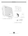
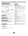
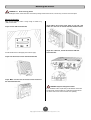
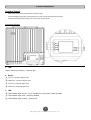
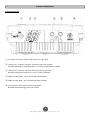
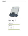
User’s Manual
CPSPV5000ETL
CPSPV4000ETL
CyberPower Systems Inc.
www.cpsww.com
IMPORTANT SAFETY INSTRUCTIONS
Save These Instructions! This manual contains important constructions that shall be followed during the installation and maintenance of the CyberPower Grid
Tie Solar Inverter.
CAUTION! Before installation and using the Inverter, read all
instructions and cautionary markings on the inverter and appropriate
sections of this guide.
About This Manual
This purpose of this Installation & Operation Manual is to provide
explanations and procedures for installing, operating, maintaining, and
troubleshooting the CyperPower Grid Tie Solar Inverter.
CAUTION! To reduce risk of fire hazard, do not cover or obstruct the
heat sink.
Scope
CAUTION! Observe the clearance recommendations. Do not install the
Inverter in a zero-clearance or non-ventilated compartment. Overheating
may result.
This manual provides safety guidelines, detailed planning and setup
information. It provides procedures for installing the inverter and
information about operating and troubleshooting the unit. It dose not
provide details about particular brands of photovoltaic (PV) panels. You
need to consult individual PV manufacturers for this information.
CAUTION! Use only accessories recommended or sold by the
manufacturer. Doing otherwise may result in a risk of fire, electric shock,
or injury to persons.
Audience
CAUTION! To avoid a risk of fire and electric shock, make sure that
existing wiring is in good condition and that wire is not undersized. Do not
operate the Inverter with damaged or substandard wiring.
This manual is intended for anyone who needs to install and operate the
inverter. Installers should be fully educated on the hazards of installing
electrical equipment. Certified electricians or technicians are
recommended.
CAUTION! Do not operate the Inverter if it has received a sharp blow,
been dropped, or otherwise damaged in any way.
CAUTION! Do not disassemble the Inverter. It contains no
user-serviceable parts. Attempting to service the Inverter yourself may
result in a risk of electrical shock or fire and will void the factory warranty.
Abbreviation and Acronyms
CAUTION! To reduce the risk of electrical shock, disconnect both AC
and DC power from the Inverter before attempting any, maintenance or
cleaning or working on any circuits connected to the inverter. Turning off
controls will not reduce this risk. Internal capacitors remain charger for 5
minutes after disconnecting all source of power.
AC:
Alternating Current
DC:
Direct Current
CAUTION! The Inverter must be connected to an equipment-grounding
conductor directly or via the AC ground.
LCD:
Liquid Crystal Display
ATTENTIO: Risk of burning: During operation the case temperature
may exceed 140 (60 ) , do not touch.
LED:
Light Emitting Diode
HIGH VOLTAGE: Before opening the device, disconnect from the grid
and the PV generator. The device may only be opened by an electrician.
MPPT:
Maximum Power Point Tracking
PC:
Personal Computer
PV:
Photovoltaic
PWM:
Pulse Width Modulation
!
CAUTION! Cautions identify conditions or practices that could
result in damage to the unit or other equipment.
Vac:
Volts AC
IMPORTANT: These notes describe things which are important for you to
know, but not as serious as a caution or warning.
Vdc:
Volts DC
VMP:
Voltage at Maximum power
VOC:
Open Circuit Voltage
℉ ℃
The following conventions are used in this guide.
!
WARNING! Warnings identify conditions that could result in
personal injury or loss of life.
1
Copyright © 2012 CyberPower Systems, Inc.
UNPACKING
2) Stainless wall mount bracket
3) User’s manual
4) Warranty card
1) CPSPV5000ETL or CPSPV4000ETL module
5) Self-tapping screws: M6*30L(5)
2
Copyright © 2012 CyberPower Systems, Inc.
Installation
CyperPower Grid Tie Solar Inverter
Inverter Location
The CyberPower Grid Tie Solar Inverter is designed to convert solar
electric (photovoltaic or PV) power into utility-grade electricity that can be
used by the home or sold to the local power company.
!
WARNING! Burn hazard
Do not install in a location where people can accidentally come into
contact with the inverter. High temperatures can be present on the
inverter, causing a potential burn hazard.
In extreme condition, the inverter chassis can reach temperatures over
70
(158 ), which can cause skin burns if accidentally touched.
Ensure that the inverter is located away from normal traffic areas.
Installing the inverter consists of mounting it to the wall and connecting
the DC input to a PV array and the AC output to the utility. See below
figure for a simple diagram of a typical installation.
℃
℉
Inverter failure due to improper installation will void the inverter warranty.
Consider the following when determining where to install the inverter.
Fire Safety
Do not install anywhere near combustible or flammable materials.
Indoor/Outdoor
The inverter uses a Type IP65-rated enclosure that can be mounted
indoors or outdoors.
In order to operate, the inverter must have grid power available and
connected. It will not provide backup power if the AC grid fails.
Orientation
Installation Options
Temperature
The inverter may be installed as a single inverter, or in a multiple inverter
configuration.
For CPSPV5000ETL / CPSPV4000 ETL, only one PV array can be
connected to the inverter.
Ensure that the inverter is mounted in a location where the ambient
temperature range is -20 to +60 . When the temperature is over
+40 , the inverter may de-rate power.
The inverter must be mounted vertically on a wall or pole. Do not mount
the inverter horizontally.
℃
℃
℃
Ground Clearance
Single Inverter Installation
Outdoors, the inverter requires at least 50 cm (19.7 inches) of clearance
between the bottom of the unit and the ground.
Indoors, it is recommended that the same clearance between the bottom
of the unit and the floor be used.
In this configuration, a single inverter collects the harvested solar energy
and route the power to the main utility service panel to be used by the
loads. Any surplus power not used by the loads will be directed to the
utility grid.
Multiple Inverter Installation
Distance
If multiple inverters are used, each inverter must be wired to an
independent PV array. In this configuration, each inverter collects the
harvested solar energy from a separate PV array and routes the power to
the main utility service panel to be used by the loads. Any surplus power
not used by the loads will be directed to the utility grid.
To minimize copper losses, ensure that wire lengths between the PV
array and the inverter and between the inverter and the Main Utility
Service Panel are kept to a minimum.
The maximum distances will depend on wire gauges and PV array output
voltages
Debris free
Excessive debris (such as dust, leaves, and cobwebs) can accumulate
on the unit, interfering with wiring connections and ventilation. Do not
install in a location where debris can accumulate (under a tree, for
example).
Planning the Installation
The following issues need to be considered when planning for an
installation using the inverter. See the specified sections for more
information.
Inverter Location?
PV Array Requirements?
Grounding Requirements?
Routing the wires?
Ensure that you have obtained all permits required by local authorities or
utilities before commencing installation.
3
Copyright © 2012 CyberPower Systems, Inc.
Installation
PV Array Requirement
PV Voltage requirements
The maximum power point voltage of a string connect to the inverter
should be a minimum of 320Vdc. If it is less than 320Vdc, the inverter will
continue to operate, but it will regulate the PV voltage to 320Vdc.
Because the array will not be operating at its maximum power point, this
may result in lower than expected energy harvest.
!
WARNING! Shock hazard
Whenever a PV array is exposed to sunlight, a shock hazard exists at the
output wires or exposed terminals. To reduce the risk of shock during
installation, cover the array with an opaque (dark) material before making
any connections.
Maximum PV Power
IMPORTANT:
The PV array should be free of shade. This requirement includes even
small obstructions such as vent pipes, chimneys and power lines. A small
amount of shade can have a disproportionately high impact on system
performance.
General Recommendations
It is important that the PV array is installed correctly to the manufacturer
specifications and to local code requirement.
The solar array should be sized such that the maximum power output
dose not exceeds the limit of the MPPT operation window. The array
voltage should never exceed 900 VOC (open circuit voltage) under any
thermal condition. Likewise, ensure that ISC (short circuit current) rating
of the array at any temperature does not exceed the short circuit current
of the inverter.
Guideline for Matching PV Array Size to Solar Inverter Input
For determining the number of panels required in the PV string (panels
connected in series), you must ensure that the following requirements are
met:
Equipment and Installation Recommendation
Equipment recommendations
-
All electric equipment should be listed for the voltage and current
ratings necessary for the application.
-
All wiring should be sized correctly to minimize voltage drop.
-
All required over-current protections should be include the system
and accessible for maintenance.
-
Integral roofing products should be properly rated.
Installation recommendations
-
All electrical terminations should be fully tightened, secured, and
strain relieved as appropriate.
-
All mounting equipment should be installed according to the
manufacturer specifications.
All roof penetrations should be sealed with an acceptable sealing
method that does not adversely impact the roof warranty.
All wires, conduit, exposed conductors and electrical boxes should
be secured and supported according to code requirements.
-
1.
To avoid damage to the inverter, ensure that PV array output will
never exceed 900Vdc under any conditions.
2.
Do not exceed the maximum array short circuit current rating
marked on the inverter.
3.
To achieve maximum energy harvest from your array, ensure that
the VMP (voltage at maximum power) dose not drop below 310Vdc
under most condition.
CPSPV5000ETL
CPSPV4000ETL
1
1
Input current limitation
17A
13.5A
Max. Input short circuit current
20A
15A
MPPT start voltage (Vdc)
320
320
MPPT window (Vdc)
250~900
250~900
Inverter full load range (Vdc)
310~750
310~750
Inverter de-rating range (Vdc)
250~310
250~310
Maximum input voltage (Vdc)
900
900
MPPT tracker
PV Voltage and MPPT Requirement
MPPT operational window
The MPPT software maximizes the output energy of solar arrays as long
as the operating voltage is within the operational window. Ensure that the
PV array used in the system operates within the MPPT operational
window. Effects of array voltages outside of the MPPT operational
window are shown in below Table.
Vo l t a g e
E f f e c t o f A r r a y Vo l t a g e
Inverter Mode
(Vdc)
<250
Will shut down
Shutdown
Maximum harvest of solar energy. (limit
250~310
MPPT window
input max current 17A)
310~750
Maximum harvest of solar energy.
MPPT window
Maximum harvest of solar energy. (limit
750~900
MPPT window
input max power)
Will shut down and may cause damage
>900
Shutdown
to the inverter.
4
Copyright © 2012 CyberPower Systems, Inc.
Installation
Routing the wires
Grounding Requirements
Preparing for the Installation
Ensure your local utility is consulted for any requirements for connecting to
or returning power to the grid. Obtain all permits necessary to complete the
installation. Consult your local and national electrical codes for more
information.
!
WARNING! Shock hazard
The inverter must be grounded by connection to a grounded permanent
wiring system.
AC grounding
This section includes the following topic:
1. Wiring
The wires to AC terminal:
Acceptable wire size:
For CPSPV5000ETL: From #10 AWG (4mm2 to 6mm2).
For CPSPV4000ETL: From #12 AWG to #10 AWG (3mm2 to 6mm2).
The wires to DC connectors:
Recommended Type:
For PV (+): PV-KBT4/2,5I with 1.5~2.5mm^2 cable (double-isolation)
For PV (-): PV-KST4/2,5I with 1.5~2.5mm^2 cable (double-isolation)
The inverter must be connected to a grounded, permanent wiring system
via the inverter ground terminal.
The ground terminal must also be connected to the main utility breaker
panel ground bar and to the house-grounding rod according to
requirement.
Lightning protection
Reduce the risk of lightning damage by using a single-point grounding
system. In this system, all ground lines terminate at the same point. This
point normally is the main utility ground installed by the utility company to
provide a ground for the house wiring. This ground usually consists of a
copper rod driven 1.5 to 2.5 meters (6 to 8 feet) into the earth.
IMPORTANT:
Wiring should be not undersized. Undersized wiring can result in
significant power losses and reduction in system efficiency.
2. AC Circuit breaker
This breaker must be sized to handle the rated maximum output voltage
and current of the inverter. (Please refer to the inverter specification)
Recommended AC Circuit Breaker:
For CPSPV5000ETL: 32 Amps / 250 Vac.
For CPSPV4000ETL: 25 Amps / 250 Vac.
5
Copyright © 2012 CyberPower Systems, Inc.
Mounting the inverter
!
、Shock and Energy Hazard
WARNING! Fire
Before installing the inverter, read all instructions and cautionary markings located in this manual, on the PV array, and on the main service panel.
Mount the inverter
Make sure the supporting surface is strong enough to handle 75 kg
(160lb) for the inverter.
Step4: Move the inverter from right to left side, and
make sure the hole is locked with wall mount bracket.
Step1: Fix the wall mount bracket
Step5: Use cable ties, and fix the inverter with wall
Use the attached screws / Self-tapping screws: M6*20L (5pcs)
mount bracket.
Step2: Put the inverter on the wall mount bracket
Step3: Make sure the host of inverter on the incision of
the wall mount bracket
!
WARNING! Equipment damage Shock hazard
If your installation location requires that you drill additional conduit holes
into the bracket, ensure that there are no metal shavings left inside the
unit. These could cause a short circuit when unit is operating.
6
Copyright © 2012 CyberPower Systems, Inc.
Inverter Introduction
Standard Feature
-
Sealed inverter section protecting power electronic components (IP65)
-
Liquid Crystal Display providing easy-to-read system status and daily cumulative energy production information
-
Three LED indicator lights providing status, ground fault and other warning indication
Front Panel Feature
1. LCD:
Graphic liquid crystal display / “160*128” dots
2. Button:
A : Up key: select the display item
○
B : Down key: select the display item
○
C : Esc key: escape to upper level
○
D : Enter key: enter into next level
○
3. LED:
E : LED Indicator Light (Green) – Flash: Standby for reconnection / Solid: Operation
○
F : LED Indicator Light (Red) – Warning condition
○
G : LED Indicator Light (Yellow) – Ground fault
○
7
Copyright © 2012 CyberPower Systems, Inc.
Inverter Introduction
Rear Panel Feature
1 : DC switch: The device which can disconnect the solar input
○
2 : Solar input (- / negative): DC wires connect to solar array negative
○
-
Recommended type: PV-KST4/2,5I with 1.5~2.5mm^2 cable (double-isolation)
3 : Solar input (+ / positive): DC wires connect to solar array positive
○
-
Recommended type: PV-KBT4/2,5I with 1.5~2.5mm^2 cable (double-isolation)
4 : M20*1.5 cable glands * 2pcs: For RS-485 communication
○
5 : M20*1.5 cable gland * 1pcs: For RM card communication
○
6 : AC connector (male): Connect to the utility output
○
-
Recommended female type: 96.0314154.3 (Wieland)
8
Copyright © 2012 CyberPower Systems, Inc.
Startup Procedure
Check the PV Array DC Voltage
1.
Uncover the PV arrays and expose them to full sunlight. The sunlight must be intense enough to produce the required output voltage.
2.
Measure the PV array open circuit DC voltage across the DC positive (+) and negative (-) terminals. This voltage must greater than 320
volts DC (to energize the electronics) and less than 900 volts DC (to prevent damage to the inverter).
Check the AC Utility Voltage
1. Switch on the main and inverter breakers in the main electrical service panel.
2. Using an AC voltmeter, measure the AC open circuit utility voltage between L (L1) and N (L2). Ensure the voltage is at approximately the
nominal value. The inverter operates with the voltage range around the nominal value.
See “Electrical Specification”, output section for the utility voltage operating range for your inverter model.
Start up the Inverter
1.
Switch the DC and AC disconnection switches (breakers) to the ON position.
2.
Check the inverter LCD. The startup screens should appear for several seconds, and then the “Countdown xx:xx” special screen will
appear until protection timer countdown is completed.
Disconnect Test
The disconnect test is designed to verify correct operation of the inverter both on initial operation and periodically through its life as required
by the utilities. This test ensures that inverter dose not send electricity to the utility grid when local utility has shut off the grid for repairs, or
when the utility wiring is damaged.
To run the disconnect test
1.
Switch off the AC circuit for the inverter
This can be accomplished by switching the breaker on the main panel that feeds the inverter(s). The disconnection for the home or
business may be used as well.
2.
Have someone watch the front panel of the inverter to ensure the green light on the front of the inverter goes out.
The green light goes out when AC circuit is switched off, disconnecting the inverter from the AC grid. The front panel display will show
an AC voltage and frequency fault display, indicating that the AC is out of the operating range.
3
Switch on the AC circuit for the inverter
The inverter responds by starting it reconnecting protection timer. Ensure that the inverter does not produce power before the
countdown is over. After completing the countdown, the green light turns on and the inverter begins to send power to the grid. The
display returns to show the power being produced and total kWh produced to date.
IMPORTANT:
The default voltage, frequency and reconnect delay values are programmed into the unit at time of shipment from the factory. No changes to these settings
can be made in the field by the user. Only authorized personnel with utility permission may change these settings.
9
Copyright © 2012 CyberPower Systems, Inc.
Monitoring the Inverter
After installation, at the first startup, the
1. Home page
following setting should be set through the
display.
Select code
Pac kW: Right now the inverter provides how much power to the grid.
E-Total: From the installation to now, the inverter provided how much
energy to the grid.
E-day: Today the inverter provided how much energy to the grid.
Select language
Press “Enter” key
2. Main menu:
Select date & time
After you select above three items, the
display will enter into “Home Page”
10
Copyright © 2012 CyberPower Systems, Inc.
Monitoring the Inverter
In “Main Menu”, select Energy total, then press
“Enter” key
2.1 Energy Totals:
In “Main Menu”, select Data Logger, then press “Enter” key
In “Main Menu”, select Multi meter, then press
“Enter” key
2.2 Multi meter:
In “Data Logger”, select Daily Log, then press “Enter” key
2.3 Data Logger:
2.3.1
Daily Log:
In “Data Logger”, select Monthly Log, then press “Enter” key
2.3.2 Monthly Log:
11
Copyright © 2012 CyberPower Systems, Inc.
Monitoring the Inverter
In “Data Logger”, select Yearly Log, then press
“Enter” key
2.3.3
Yearly Log:
In “Config”, select Date & Time, then press “Enter” key
2.5.1 Date & Time:
In “Main Menu”, select Log Book, then press
“Enter” key
2.4 Log Book:
In “Config”, select Grid Set, then press “Enter” key
2.5.2
Grid Settings:
IMPORTANT:
There are over last 100 dated failure reports on the NS
protection can be read.
In “Main Menu”, select Config, then press
“Enter” key
2.5 Config:
IMPORTANT:
The settings only can be used by authorized personnel with utility
permission.
12
Copyright © 2012 CyberPower Systems, Inc.
Monitoring the Inverter
In “Config”, select Display Set, then press
“Enter” key
2.5.3
Display Settings:
In “Config”, select Installer Code, then press “Enter” key
In “Config”, select Device Info, then press
“Enter” key
2.5.4
2.5.5
Installer Code:
Device Info:
IMPORTANT:
The settings only can be used by authorized personnel with utility
permission.
In “Config”, select RMCard Set, then press “Enter” key
2.5.6 RMCard Settings:
IMPORTANT:
The settings only can be used by authorized personnel with utility
permission.
13
Copyright © 2012 CyberPower Systems, Inc.
Warning / Error / Fault List Table
Warning table
failure
W00
Solar input voltage low
W04
Solar input voltage high
Hardware
F15
Error table:
E00
DSP ADC2
main
DSP ADC3
main
DSP ADC4
failure
No Grid
Hardware
F18
AC frequency high (According to
E01
main
failure
Hardware
F17
DSP ADC1
failure
Hardware
F16
main
failure
code setting table)
Hardware
F19
AC frequency low (According to
E02
redundant
MCU
ADC1 failure
code setting table)
F20
Hardware efficiency failure
AC voltage high (According to code
E03
Hardware
F22
setting table)
communication
1
communication
2
failure
AC voltage low (According to code
E04
Hardware
F23
setting table)
F24
Fault table
(Usually you need to call service people if
there is always fault condition happened)
current
(According
to
code
setting table)
F05
Temperature sensor 1 low
F06
Temperature sensor 1 high
Hardware temperature sensor 1
F07
F08
failure
Temperature sensor 2 high
Hardware temperature sensor 2
F09
Residual
current
failure
(According
to
setting
code
table)
Hardware DC injection of output
F01
failure
F25
Hardware RCMU failure
F26
Input insulation failure
F28
Hardware relay short
F29
Hardware relay open
F31
Hardware DC Bus 1 OVP
F33
Hardware DC Bus 2 OVP
F36
AC output current high (fast)
F37
AC output current high (slow)
F42
Hardware CT failure
F45
Hardware AC current OCP
F60
DC input current high (slow)
F70
DC input current high (fast)
failure
F10
Temperature sensor 3 high
F11
Hardware temperature sensor 3
14
Copyright © 2012 CyberPower Systems, Inc.
TECHNICAL SPECIFICATIONS
Model
Feature
CPSPV4000ETL
Grid tied PV inverter
Non-isolated (transformer-less)
Adjustable reactive power
Outdoor enclosure (IP65)
Type of equipment
Input
Absolute maximum PV input
voltage
Operation voltage range
MPP voltage range @nominal
power
Input power capture
Rating input voltage
Inverter wake up voltage
Start voltage
MPPT tracker
Input current limitation
Max backfeed current
Maximum efficiency@650Vdc
European efficiency@650Vdc
900 Vdc
250 ~ 900 Vdc
310 ~ 750 Vdc
>99%
650 Vdc
< 200 Vdc (DC power supply on)
320 Vdc
1 tracker
13.5 Adc
97.6%
97.0%
97.8%
97.3%
Voltage and current limitation
Array impedance measurement
Residual current measurement
Input voltage deviation < 2%
Input current deviation <3%
Input power deviation <3%
Input detection tolerance
Output
Output protection
Output detection tolerance
17 Adc
0A
Input protection
Output rating power
Grid
Grid rating voltage
Grid voltage range (Over /
under voltage disconnect)
Over / under voltage
disconnect time
Grid rating current
Grid maximum continuous
current
Grid rating frequency
Grid maximum inrush current
Maximum output fault current
Maximum output overcurrent
protection
Grid frequency range (Over /
under frequency disconnect)
Over / under frequency
disconnect time
Active islanding method
Reconnect time (After grid
recover)
Output current DC component
Output current harmonic
distortion
Adjustable reactive power
range
Nighttime power consumption
CPSPV5000ETL
4000 Watt
5000 Watt
(For VDE-AR-N 4105: 4600 Watt )
Single phase
230 Vac
180 ~ 270 Vac (According to code setting table)
17.4 A
According to code setting table
21.7 A (20 A Germany)
20 A
24 A
50 / 60 Hz
<150 A
>30A
40 A
50 A
50 / 60 +/- 5 Hz (According to code table setting)
According to code setting table
Yes
According to code setting table
According to code setting table
< 5%
0.8 inductive ~0.8 capacitive
< 1 Watt
Output AC fuse
Current limitation and thermal de-rating
Over temperature protection
Utility voltage deviation < 1%
15
Copyright © 2012 CyberPower Systems, Inc.
TECHNICAL SPECIFICATIONS
Power limitation
Information
Communication
LED
LCD display
Control switches
Display data
RTC (Real time counter)
Data storage
Regulatory
Safety
Grid interface
Emission
Harmonic current emissions
Voltage fluctuations and flicker
Immunity
Operation Environment
Operating Temperature
Storage temperature
Relative humidity
Audible noise
Operating elevation
Vibration / Drop
Physical
Dimensions (unit)
Dimensions (Package)
Net Weight
Gross Weight
Enclosure rating
Installation type
DC connector
AC connector
Utility frequency deviation < 0.05Hz
Output current deviation < 3%
Output power deviation < 3%
Countdown timer deviation <1 sec
Temperature sensor on heat-sink & internal air temperature
Output voltage under 195 Vac
RS485 / Ethernet (optional) / WiFi (optional)
Green / Red / Yellow
160 * 128 dots
Up / Down / Esc / Enter
Real-time output power
Inverter status
Accumulate today output energy
Accumulate lifetime output energy
Event message
Utility voltage, frequency
PV voltage, power
Firmware revision
Inverter ID
10 years life
Accumulate historical energy
IEC 62109-1/2
VDE-AR-N 4105 / VDE0126-1-1 A1/ UTE C 15-712-1
EN 55022:2006
EN 61000-3-12:2005
EN 61000-3-11:2001
EN 55024
-20
℃ to 60℃(full power -20℃ to 40℃)
-20℃ to 60℃
4% ~ 100%
<36dB
0 ~ 2000 m ( 0 ~ 6666 ft)
ISTA_1A standard
L x W x H = 487 x 497 x 191mm
L x W x H = 615 x 615 x 380 mm
26 Kg
30.5 Kg
IP 65
Wall mount
2 pairs of Multi Contact connectors
Waterproof AC connector
CyberPower Systems Inc.
www.cpsww.com
16
Copyright © 2012 CyberPower Systems, Inc.
TECHNICAL SPECIFICATIONS
Explanation of symbols
Beware of dangerous electrical voltage.
Energy storage timed discharge with 1 minutes.
Beware of hot surface.
Observe enclosed documentation.
There are special requirements.
The inverter complies with the requirements of the applicable EC guidelines.
The inverter must not be disposed of together with the household waste.
17
Copyright © 2012 CyberPower Systems, Inc.
Code setting table
Code table number
Code
2
3
4
5
VDE-AR-N4105
VDE0126-1-1
UTE C15-712-1
VDE0126-1-1/TW
Default
Setting
Trip time
Setting
Trip time
Setting
Trip time
Setting
Trip time
Start up time
60
--
30
--
30
--
30
--
Reconnect time (T < 3S)
60
--
5
--
5
--
300
--
Reconnect time (normal)
60
--
30
--
30
--
300
--
Voltage high OFF (Fast)
264.5
0.08 sec
264.5
0.2 sec
255.3
0.2 sec
242
0.2 sec
Voltage high ON (Fast)
250.7
--
259.5
--
251.3
--
237
--
Voltage low OFF (Fast)
184.0
0.08 sec
184
0.2 sec
184
0.2 sec
187
0.2 sec
Voltage low ON (Fast)
197.8
--
189
--
189
--
192
--
Frequency high OFF (Hz)
51.50
0.08 sec
50.2
0.2 sec
50.2
0.2 sec
60.3
0.2 sec
Frequency high ON (Hz)
50.05
--
50.15
--
50.15
--
60.1
--
Frequency low OFF (Hz)
47.50
0.08 sec
47.5
0.2 sec
46
0.2 sec
59.7
0.2 sec
Frequency low ON (Hz)
47.55
--
47.55
--
46.1
--
59.9
--
Voltage high OFF (Slow)
253.0
600 sec
253
600 sec
253
600 sec
--
--
Voltage high ON (Slow)
250.0
--
250
--
250
--
--
--
Voltage low OFF (Slow)
--
--
--
--
--
--
--
--
Voltage low ON (Slow)
--
--
--
--
--
--
--
--
DC Injection (mA)
--
--
1000
0.2 sec
1000
0.2 sec
0.45%
0.2 sec
Ground Current (mA)
300
0.3 sec
300
0.3 sec
300
0.3 sec
300
0.3 sec
Insulation
Yes
5 sec
Yes
5 sec
Yes
5 sec
Yes
5 sec
Islanding
Yes
Yes
Yes
Yes
Islanding Factor
100
100
100
100
Active Power
Yes
--
--
--
Reactive Power
Yes
--
--
--
Frequency de-rating
Yes
--
--
--
Power slow-up
Yes
--
--
--
18
Copyright © 2012 CyberPower Systems, Inc.
Code setting table
Code table number
Code
6
7
8
VDE0126-1-1/A1
IEC62116 MEA
IEC62116 PEA
Default
Setting
Trip time
Setting
Trip time
Setting
Trip time
Start up time
30
--
120
--
60
--
--
Reconnect time (T < 3S)
5
--
120
--
20<t<300
--
--
Reconnect time (normal)
30
--
120
--
20<t<300
--
--
Voltage high OFF (Fast)
264.5
0.2 sec
241/311
2/0.05 sec
242/264
1/0.16 sec
Voltage high ON (Fast)
259.5
--
240
--
237
--
Voltage low OFF (Fast)
184
0.2 sec
199/114
2/0.1 sec
198/110
2/0.3 sec
Voltage low ON (Fast)
189
--
200
--
203
--
Frequency high OFF (Hz)
51.5
0.2 sec
51.1
0.1 sec
51.1
0.1 sec
Frequency high ON (Hz)
50.5
--
51
--
51
--
Frequency low OFF (Hz)
47.5
0.2 sec
48.9
0.1 sec
47.9
0.1 sec
Frequency low ON (Hz)
47.55
--
49
--
48
--
Voltage high OFF (Slow)
253
600 sec
--
--
--
--
Voltage high ON (Slow)
250
--
--
--
--
--
Voltage low OFF (Slow)
--
--
--
--
--
--
Voltage low ON (Slow)
--
--
--
--
--
--
DC Injection (mA)
1000
0.2 sec
1000
0.2 sec
1000
0.2 sec
Ground Current (mA)
300
0.3 sec
300
0.3 sec
300
0.3 sec
Insulation
Yes
5 sec
Yes
5 sec
Yes
5 sec
Islanding
Yes
Yes
Yes
Islanding Factor
100
100
100
Active Power
--
--
Yes
Reactive Power
--
--
Yes
Frequency de-rating
Yes
--
--
Power slow-up
Yes
--
--
19
Copyright © 2012 CyberPower Systems, Inc.
Setting
Trip time
Code setting table
Reactive power measurement
20
Copyright © 2012 CyberPower Systems, Inc.