1
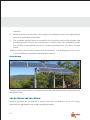
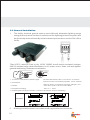
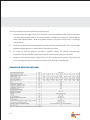
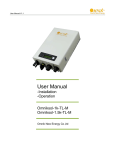
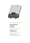
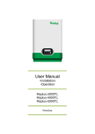
Installation and User Manual
Moser Baer Photo Voltaic Modules
Max Series- Crystalline Silicon Modules
Model - MBPV CAAP
Re-energizing the World!
PLEASE READ THIS MANUAL CAREFULLY BEFORE INSTALLING OR
USING THE MODULES
This manual contains critical safety instructions for the PV module that must be
followed during the installation and maintenance of PV modules. Failure to follow
these instructions may result in bodily injury or damage to property. Working on a
photovoltaic system requires specialized knowledge and should only be attempted
by qualified professionals.
Introduction
Moser Baer is a world leader in development and high-volume- manufacturing of
technology products. Our prime commitment is to produce quality products that last
for many years. Moser Baer PV modules are designed for versatility in application and
suited for residential, commercial and industrial applications.
The modules use high efficiency Multi Crystalline silicon solar cells; high transmitivity,
low iron content, tempered and toughened glass; and premium quality encapsulation
materials having superior UV and thermal properties.
Laminates are framed in anodized aluminium frames and come along with a
permanently attached junction box with a 12AWG cable terminated in PV-KBT4 and
PV-KST4 multi contact connectors.
"MBPV modules are rated for fire class C.
Doc. No. PV/CN/ENG/WI/011
Rev no. 01, Rev. Date: 10/05/2010
Installation and User Manual
Moser Baer Photo Voltaic Modules
Max Series- Crystalline Silicon Modules
Model - MBPV CAAP
Index
Installation and User manual
Moser Baer Max Series Photovoltaic Modules
Model : MBPV CAAP Wattage Range : 180 W-220W
Contents
1. Warning Notice
1.1 General safety
1.2 Handling safety
1.3 Installation safety
3
3
3
4
2
Mechanical Installation
2.1 Site Selection
2.2 Tilt Angle Selection
2.3 Mounting Installation
2.3.1 General Installation
2.3.2 Ground Mounting
2.3.3 Roof mounting
2.3.4 Pole mounting
5
5
5
6
6
7
8
9
3
Electrical Installation
3.1 Grounding Method
3.2 General Installation
9
9
11
4
Maintenance
13
5
Module Specifications
13
6
Product identification
14
7
Disclaimer of Liability
14
8
Notes
16
WARNING Hazardous electricity ! Can shock burn or cause death.
WARNING
1.1
1. Photovoltaic modules can generate electricity upon exposure to light. The voltage
of a single module is less than 45VDC, but the shock hazard increases as modules
are connected in parallel producing higher current. The shock hazard increases
as modules are connected in series producing higher voltages.
2. All instructions should be read and understood before attempting to install, wire,
operate, and maintain the photovoltaic module. Contact with electrically active
parts of the module such as terminals can result in burns, sparks, and lethal
shock whether the module is connected or disconnected.
3. Do not disconnect the connector of the modules while under load. To achieve
disconnect while under load, a provision of High Voltage Slow Blow DC Fuse or
High Voltage DC MCB should be provided in the Array Junction Box.
1.2
1.
2.
3.
4.
5.
6.
3
CAUTION
To avoid the hazard of electric shock and injury, cover the entire front surface of the
PV modules with a dense, opaque material such as a cardboard sheet, during
installation and handling of the modules.
Do not hit or put excessive loads on the glass or back sheet or twist the frame, the
glass may break, PV cells may break.
Do not stand or step on the PV module, the glass may be slippery and there is a
risk of injury or electric shock if glass breaks.
PV modules are heavy , please handle with care. Do not drop or allow objects to fall
on the PV module.
Do not twist the interconnect cable excessively
Unauthorized persons-except the qualified licensed professional--should not
open the cover of the junction box to avoid the hazard of electric shock. Provide
suitable guards to prevent yourself from direct contact with 30 VDC or greater to
avoid the hazard of electric shock or injury.
7.
When carrying a module, two or more people should carry it by its frame and wear
non-slip gloves (to avoid injury by a slipping module, to a foot, or cuts by the edge
of a frame, and so on).
8.
Do not lift the modules by grasping the module junction box or electrical cables.
1.3 Installation Safety:
WARNING
All PV modules shall be installed in accordance with applicable codes and
regulations, including but not limited in USA to National Electrical Code (NEC)
and in Canada in accordance with CSA C22.1, Safety standard for electric
installation, Canadian electrical Code (CEC).
CAUTION
1.
Only PV modules with the same cell type and size should be connected in series
2.
Follow all safety instructions of other components used in the system
3.
Avoid uneven shade on the PV module surface .Shaded cells may become hot
(hot spot phenomenon) which may result in permanent damage to the module.
4.
Do not drill holes in the frame, it may compromise the frame strength and cause
corrosion of the frame also void the warranty.
5.
To avoid the hazard of electric shock, work only under dry conditions, with dry
modules and tools.
6.
Do not puncture or damage the back-sheet of a module, to avoid the hazard of
electric shock and fire.
7.
To avoid the hazard of electric shock and injury, be sure to completely ground all
modules & do not disassemble the module, or remove any part installed by the
manufacturer.
8.
Since sparks may occur, do not install the module where flammable gases or
vapors are present.
9.
Never leave a module unsupported or unsecured.
10. Do not use mirrors or other magnification device to artificially concentrate sunlight
onto the modules.
4
11. Do not change the connection of bypass diodes to avoid the hazard of electric
shock and injury.
12. MBPV CAAP series of modules qualified for Application class A
2 MECHANICAL INSTALLATION
2.1 Site Selection:
1.
PV modules are intended for outdoor use only and should be installed in a location
where they will receive maximum sunlight throughout the year.
2.
In Northern latitudes, the modules would normally face true south & in the
Southern Latitudes, the modules should face north for optimum power output
3.
Avoid trees, buildings or obstructions which could cast shadows on the solar
modules especially during the winter months when the arc of the sun is lowest over
the horizon.
4.
Solar modules produce maximum power when they are pointed directly at the sun.
5.
For installations where the solar modules are mounted to a permanent structure,
the solar modules should be tilted for optimum winter performance.
2.2 Tilt Angle Selection :
More sunlight per square foot falls on a perpenicular surface (90 deg to the suns ray is
optimal).Less sunlight falls on a vertical surface & horizontal surface.
The module tilt angle is measured between the solar modules and
the ground
Tilt angle Table:
Site Latitutde in
Degrees
0° to 15°
15° to 25°
25° to 30°
Fixed tilt angle
15°
same as
latitude
latitude +5° latitude +5° latitude +5° latitude +5°
5
30° to 35°
35° to 40°
40°
Sun Arc Table:
Latitude
10°
15°
20°
25°
30°
35°
40°
45°
Summer
12.71°
13.02°
13.34°
13.7°
14.08°
14.54°
15.02°
16.62°
Winter
11.54°
11.24°
10.92°
10.58°
10.21°
9.80°
9.33°
8.76°
2.3 Mounting Installation:
General Installation
1.
Place the modules on top of the structure & mount it by using the pre-drilled
elliptical mounting holes as shown below & fix it firmly on the structure using the
mounting hardware`s (M4 nuts & Bolts).
2.
Always select the length of mounting screw after considering a clearance of 5-10
mm between the module back face & screw face to avoid any breakage of
module while tightening (as shown below).
6
3.
The support module mounting structure must be made of durable , corrosion
resistant and UV resistant material.
4.
Modules should be firmly fixed in place in a manner suitable to withstand all
expected loads, including wind & snow loads. Determine wind loads for the
installation site & consult it from safety departments for the specific requirements.
5.
All hardware like bolts, nuts & washers should be of stainless steel so as to
eliminate the possibility of rust.
6.
The Open circuit Voltage exceeds the rated voltage. Take care that the open
circuit voltage multiplied by the number of modules in series is not higher than the
Max. system voltage (IEC-1000V/ UL 600V)
7.
Module mounting must use the pre-drilled mounting holes in the frame.
8.
Do not drill additional mounting holes on the frame & glass surface of the module.
Doing so will void the warranty
Ground Mount
1.
Select the lowest height of the structure to prevent the lowest height of the module
from being covered by snow for a long time in winter.
2.
In addition ensure that the lowest portion of the module is placed high enough so
7
8
that it is not shaded by trees or plants and not damaged by sand or stone driven
by wind.
3.
The supporting frame/structure is used to mount modules at correct tilt angles.
4.
Clearance between the modules frame & the mounting surface is required to
prevent the junction box from touching the surface & to allow cooling air to
circulate around the back of the module. This also allows any condensation or
moisture to dissipate.
Roof Mount(Tilt Roof/Wall Installation)
1.
Roof mounted PV modules should be mounted on a fire resistant roof.
2.
Installation should be carried out in calm winds to prevent accident due to fall.
3.
Special construction or structures may be required to help provide proper
installation.
4.
Both roof construction and module installation design have an effect on the fire
resistance of a building. Improper installation may contribute to fire hazards.
Additional devices such as ground fault, fuses, and disconnects may be
9
required.
5.
Make sure that roof structure can support the installation load and might require
service of professional installers.
6.
The modules should never be sealed to the mounting surface with sealant that
prevents the junction box from touching the surface & air from circulating under
the module. Leave atleast 4 inches of clearance between the roof & the module
frame.
Module need to be securely mounted on fire resistant roof & slope less than 5 in/ft.
(127mm/305mm) required to maintain a fire class C."
Pole Mount
Choose a pole and module mounting structure that will withstand the expected snow
and wind Loads
3 ELECTRICAL INSTALLATION
Several modules are connected in series and then in parallel to form a PV array,
especially for application with a high operating voltage.
10
The DC electrical energy from a PV module may be also be converted to AC and
connected to a utility grid system. As local policies on connecting renewable energy
systems to a grid may vary from region to region, please consult a qualified system
designer or integrator to design such a system. Permits are normally required to install
such a system and the utility must formally inspect and approve such a system before it
is connected to the grid.
3.1 Grounding
The module frame must be properly grounded to avoid the hazards of electric shock or
fire.
Grounding Systems for MBPV Modules
MBPV array frame is ground in accordance
with NEC Article 250 (USA) or CEC (Canada)
Each framed module has two grounding holes
in the longer side frame rail, to connect a
graounding conductor to the module metal
frame
The grounding will be provided by fixing
earthing cable with Hex Nut, Star Tooth Washer,
Flat Washer and Hex Head Bolt as shown in the
below picture. "All the above mentioned
grounding hardware should be of stainless
steel to prevent corrosion. Recommended
Torque 1.2 - 1.8 Nm."
HEX, Head Bolt
If functional grounding is used (i.e. grounding plus
of minus), such grounding means should be
isolated from live parts by reinforced insulation
Earthing Cable
Flat Washer
Cable
Star Tooth washer
Use uncoated, stranded copper in the 10, 12
and 14 AWG wire sizes
ELECTRICAL GROUNDING OF MODULE
USING HEX, BOLT & NUT
11
Module Frame
Star Tooth washer
Flat Washer
HEX, Head Bolt
3.3 General Installation
1.
The facility electrical ground system must efficiently dissipates lightning surge
energy that may arrive via down conductors of the lightning protection system and
be electrically and mechanically robust to assure performance over the "life" off the
facility.
(Type USE-2, rated 90°Cwet or dry, 1000V 12AWG 4mm2 double insulated, halogen
free UV resistant solar cables Resistance to UV, water, ozone, fluids, salt and against
general weathering, Resistance to abrasion.
3.
3.
2.
2.
1.
1.
1. Conductor: Standard tin plated copper
No./Dia 56x0.30mmø Dia. of conductor: ø 2.56mm
2. Insulatation:
Electron beam cross-linked polyolefin, colour: Natural
3. Sheath:
Electron beam cross-linked polyolefin, halogen: free,
Outer Dia ø 5.56±0.25 mm color: Black
4. Temperature Rating:
-40°C to + 125°C
5. Following MC4 Sunlight resistant connectors should be used for field wiring.
Connectors
2.
12
All wiring should be done in accordance with applicable electrical codes.
3.
Wiring methods should be in accordance with the electrical standards & norms of
the country in which the modules are being installed.
4.
Wiring should be done only by a qualified & certified professional.
5.
Do not cut the connectors or crimp any other thimble on module wiring (Doing so
will void the warranty).
6.
The junction box, present on the back side of the module is designed to be used
with standard wiring or conduit connections.
7.
The junction box has a breather port and the breather port must not be exposed to
direct rain/water. Hence the Junction box should be mounted on the higher side of
the module when mounted with the cable outlet pointing downward, preferably.
8.
The maximum electrical rating of an acceptable series fuse is 15 amperes (for
modules with 6" cells).
9.
Keep in mind to follow the applicable codes for outdoor installation of wires in
conduits. Verify that all fittings are properly installed to protect wire against
damage & prevent moisture intrusion.
10. Number of module in series connection should not increase such that voltage
generated is beyond system voltage.
11. Blocking Diodes ;Blocking diodes can prevent night time battery discharging and
also prevent modules from loss of array output and damage by reverse current
flow. Moser Baer PV modules do not contain blocking diodes when shipped from
the factory however most battery charge regulators do have this feature.
12. By Pass Diodes ; In systems with modules in series strings, high reverse current
can flow through cells that are shaded partially or when part of a module is
shaded and rest is exposed to the sun. These currents can cause affected cells to
heat up (hot spot phenomenon) and even damage the module.To protect
modules from high reverse currents bypass diodes are provided in the junction
box (factory fitted). Diode rating -12A,200V
4 MAINTENANCE
Moser Baer Photovoltaic modules require very little maintenance, following is
13
recommended to ensure optimum performance.
1.
In view of the tilt angle of the PV modules , normal rainfall is sufficient to keep the
module glass surface clean in most weather conditions. However, if dirt build up
becomes asexcessive, clean the glass surface only with a soft cloth or sponge
using water.
2.
A mild non abrasive cleaning agent can be used for stubborn dirt. Do not use high
pressure water spray or chemicals to clean the module.
3.
In order to ensure proper operation, please check all wiring connections,
condition of the insulation and mechanical connections every six months.
4.
Observe the maintenance instructions of all components used in the systems
such as support frames, inverters, battery and charge controller etc
5 MODULE SPECIFICATIONS
14
"
Under normal conditions, a photovoltaic module may produce current and/or
voltage that are different than those listed in the datasheet.at Standard Test
Conditions. Accordingly, during system design the values of ISC and VOC marked
on UL Listed modules should be multiplied by a factor of 1.25 when determining
component voltage ratings, conductor ampacity, fuse sizes and size of controls
connected to the module output.
"
Refer to Section 690-8 of the National Electric Code for an additional multiplying
factor of 125% (80% derating)which may be applicable.
The electrical characteristics are within ± 10 percent of the individual values of Isc, Voc
& Pmax under standard test conditions (irradiance of 100 mW/cm², AM 1.5 spectrum &
a cell temperature of 25°C (77°F))".
15
6 PRODUCT IDENTIFICATION
1.
Each module has a name plate/label on its rear side detailing product type, rated
power,rated voltage, open circuit voltage, short circuit current all as measured
under Standard test condition (STC), weight , maximum fuse rating etc.
2.
Each individual module has a unique identification vide a 15 digit alpha numeric
code which is bar coded and the label is permanently affixed on the interior of the
module before lamination, visible on the front side of the module.
3.
The code is typically "MB XX X XXX XX XX XXX". The date of manufacture of the
product can be deciphered from the 6th , 7th and 8th digit - day of the year and the
9th and 10th digit - the year code.
7 DISCLAIMER OF LIABILITY
The information in this manual is based on Moser Baer's knowledge and experience
and is believed to be reliable, but does not constitute a warranty expressed or implied .
Moser Baer Photo Voltaic does not assume responsibility & expressly disclaims liability
for loss, damage, or expense arising out of, or in any way connected with installation,
operation, use, or maintenance of PV modules as per this manual. No responsibility is
assumed by Moser Baer Photo voltaic for any infringement of patents or other rights of
third parties that may result from use of PV modules. No license is granted by
implication or under any patent or patent rights.
Moser Baer Photo Voltaic reserves the right to change the manual , the specifications or
product information sheets without prior notice.
16
Notes
17
Re-energizing the World!
Doc. No. PV/CN/ENG/WI/011 / Rev no. 01, Rev. Date: 10/05/2010
Manufactured by: