1
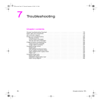
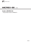
USER MANUAL
Solar Motion Activated Security Light
with 80 LEDs
SML-80G
▍DESCRIPTION
•
•
•
•
•
80pcs 0.075W LED - 6W
Solar Cell Panel with 15.4ft / 4.7m Power Cable
Color: Gray
Off / On Switch & Adjusting Knobs for Duration Time, Sensitivity, and Lux Control
Battery: 6V DC, 4A
▍PARTS LIST
1. Mounting Bracket
2. 15.4ft / 4.7m Power Cable
3. Solar Cell Panel Mounting Screws
4. Solar Cell Panel
5. Main Battery Unit
6. Transparent Light Cover
7. Main Housing Mounting Screws
8. PIR Sensor
9. Auto / Off Switch
ME
TI
+
S
10 Duration Time Adjusting Knob*
-+
10
E NS
LUX
-
11
11 Sensitivity Adjusting Knob*
12 Lux Control Adjusting Knob*
12
* Refer to page 3 to see
How to Adjust the Motion Sensor
Important: Please ensure that you charge the solar lights in maximum sunlight for a period of up to 3 days before
switching on the lights, in order that the lights work on a full charge.
www.oulighting.com
1
R201110-V12
GENERAL ELECTRICAL AND SAFETY WARNINGS
1)
2)
3)
4)
5)
6)
7)
8)
9)
The AUTO/OFF switch on the main unit must be in the OFF position when changing the battery.
Do not cut the solar cell wire. Discontinue use if the wire becomes frayed or broken.
Do not immerse components in liquid.
Do not use any other charger than the single solar charging panel provided with the SOLAR PIR SENSOR LIGHT.
This may result in injury or damage to the light and voids any warranty.
Position so that the cord is securely fastened and will not result in a hazard (such as tripping).
When changing the battery, be careful of any sharp edges that could cut you or the wires. Do not pull on the wires.
Do not connect this device to any power source other than what is supplied.
Do not handle the unit with wet hands.
The unit is not waterproof.
▍COMPONENTS LIST
•
•
•
•
•
•
•
One (1) Main Unit containing 80pcs LED lamp, PIR Motion Sensor, & Battery
One (1) Solar Cell Panel
Two (2) Main Housing Mounting Screws
Two (2) Main Housing Wall Anchors
Four (4) Solar Cell Panel Mounting Screws
Four (4) Solar Cell Panel Wall Anchors
One (1) User Manual
▍HOW TO DETERMINE WHERE TO MOUNT YOUR SOLAR PIR SENSOR LIGHT
SOUTH
SOUTH
SOUTH
Figure A
Figure
A
Figure B
Note: In the Figure B position, it is important not to let rain enter the main unit. Make sure it is mounted in a covered area.
DIRECT SUNLIGHT is important for the operation of SOLAR PIR SENSOR LIGHT. The more direct sunlight the solar cell panel
receives in daytime, the longer the light will operate.
Main Unit:
The main unit contains the lamp (80 pieces super bright white LEDs), PIR motion sensor and battery (sealed LeadAcid Rechargeable battery, 6V, 4AH). When determining where to mount this unit, please take into consideration
that the motion sensor has a detection scope of min. 20ft / 7m (in front of the light) and about 140º (horizontal) at 25°C
environmental temperature.
To mount the unit vertically as a security light, attach the unit to a solid surface as shown in figure A. To mount the unit
horizontally as convenience lighting, attach the unit as shown in figure B. Use the two wood/ sheet metal screws
provide in the package (#7 on parts list).
Solar Cell Panel:
The solar cell is the main power source for the SOLAR PIR SNESOR LIGHT. It converts the sunlight’s energy into
electricity that charges the battery in the main unit. The Solar Cell Panel requires DIRECT SUNLIGHT for as long as
possible during the daytime.
Use the four wood/sheet metal screws provide in the package (#3 on parts list) to mount the solar cell panel onto a
solid surface. Make sure it is mounted fixed into the solid surface. You can adjust the angle of the solar cell panel by
adjusting the bracket to the appropriate hook on the mounting base. It should face as much DIRECT SUNLIGHT as
possible during the daytime. At last, route the solar cell panel’s power cord to the main unit and plug it into the side
www.oulighting.com
2
R201110-V12
jack of the solar cell panel.
Important: If the main unit is mounted horizontally, it must be mounted in a covered area so rain or water cannot get into the unit
through the exposed vents.
▍FINAL ADJUSTMENT AND START-UP
After you successfully installed your SOLAR PIR SENSOR LIGHT, you are almost ready for carefree operation with a
few final steps:
Initial 3-days Charge:
On the main unit there is a switch with 2 positions:
● OFF ● AUTO
AUTO —
Position for normal operation
OFF --1) Position for delivery or long periods of non-use
2) Position for initial 3-day charge before first
adjustment and use.
Then, turn the slide switch to OFF position. The solar cell will charge the battery without activating the unit. Leave the
switch in this position for 3 sunny days to ensure that the battery has a full charge for motion sensor adjustment and
normal operation.
▍HOW TO ADJUST THE MOTION SENSOR
After the initial 3-day charge, turn the switch to AUTO position.
On the motion sensor there are three adjusting knobs: TIME / SENS / LUX
10 TIME --- Duration time: For how long you wish the light to run after motion is detected in the field, the duration
time can be adjusted from 10 seconds to 1 minute.
Note: Once the light is activated by the PIR sensor, any subsequent detection will restart the timed period again from the
beginning.
11 SENS – Sensitivity adjustment: The sensitivity of motion sensor can be affected by environmental temperature.
The lower the environmental temperature, the more sensitive the PIR sensor will be. So you can adjust the
SENS knob to compensate for the effects of temperature.
12 LUX – Lux control level: The Lux control module has a built-in sensing device (photocell) that detects daylight
and darkness. (☼) position denotes that the LED lights will be turned on by PIR during day and night, (e )
position denotes that the LED lights will be turned on by PIR only at night. You can set desired level to run the
unit the by adjusting the LUX knob.
Note: If, in daily position, the unit turns on when it is too light outside, turn the control towards (e). However, if the light is not
activating during nighttime because of a street light or bright house light, turn this control towards (☼).
Walking Test:
Point the motion sensor to face the area you want to detect motion in and set the TIME knob to minimum (-) position
and LUX knob to “light” (☼) position. Walking slowly in its detection area, the sensor can detects moving invisible
infrared radiation given off by a human body and then turn on the light. Test the coverage of the area by walking slowly
around until the sensor can no longer detect your movement.
ADJUSTMENT OF THE LAMP HOUSING:
Point the lamp housing to face the area you wish to illuminate.
▍TROUBLESHOOTING:
Symptom: Light won’t activate in normal operation.
Correction: Make sure that:
1) The main unit switch is the AUTO position.
2) The Lux control is not set too far toward (e)
1) The motion sensor is positioned to face oncoming movement
2) The solar cell is angled so that it gets plenty of direct sunlight for most of day, if not the entire day.
3) Battery charge is not too low (charge for 3 sunny days—switch turned to OFF)
Symptom: Light turns on during the day.
www.oulighting.com
3
R201110-V12
Correction: Make sure that the Lux control is not set too far toward (☼)
Symptom: Light quickly flashes on and off
Correction:
1) Move the Lux control toward (☼)
2) Low battery (charge for 3 sunny days—switch turned to OFF).
Symptom: Light is not as bright as normal.
Correction:
1) Replace LEDs
2) Low battery (charge for 3 sunny days—switch turned to OFF).
▍LED AND BATTERY REPLACEMENT
LED Replacement:
Depending on the amount of use, the LED in your SOLAR PIR SENSOR LIGHT is designed to have an average
lifetime of 100,000 hours. It is required to consult an electrical technician in case an LED needs replacement.
Battery Replacement:
Caution: When replacing the battery, the slide the switch on the main unit to OFF position.
The battery in your SOLAR PIR SENSOR LIGHT is designed to last for about 3 years. When it becomes necessary to
replace the battery, you can obtain a replacement from your local agent.
The old battery can be replaced by first removing the unit from its mounting surface. Then remove the screws on the
back of the main unit which hold the housing together. Carefully unplug the positive and negative battery leads and
unscrew the battery retainer. Carefully remove the battery from its compartment and replace by reversing this
procedure.
Caution: Make sure the (+) and (-) leads are attached correctly to the appropriate (+) and (-) battery terminals. Serious damage to
the unit may result if they are improperly connected.
Important: Dispose your used battery in an environmentally conscious manner according to governmental regulations. Please
recycle if possible.
▍CLEANING
To increase the efficiency of the solar cell charge, please clean it periodically/monthly. It is important that the solar
panel is kept free of dirt and debris. A dirty solar panel will not allow the battery to fully charge and this will shorten the
battery life and cause the light to malfunction. Please note that before cleaning the dust on the solar cell panel, the
charge will only be 4.5 volt. After cleaning, it should jump back to 7.5 volt.
▍STORAGE
If you wish to store your light indoors for more than two or three days, follow these steps to prevent damage to battery:
1) Turn the switch to OFF position
2) Store the light and solar panel where it can receive some sunlight or room light each day. The battery needs
light to maintain a charge during storage
3) During prolonged storage, unit must be fully charge once every four months, for best performance, do not
store for prolonged periods of time.
LIMITED ONE (1) YEAR WARRANTY AND EXCLUSIONS
Manufacturer warrants to the original consumer purchaser and not for the benefit of anyone else that this product at the time of its sale by Manufacturer
is free of defects in materials and workmanship under normal and proper use for one (1) year from the purchase date. Manufacturer's only obligation is
to correct such defects by repair or replacement, at its option, if within such one (1) year period the product is returned prepaid, with proof of purchase
date, and a description of the problem. This warrant excludes and there is disclaimed liability for labor for removal of this product or reinstallation. This
warranty is void if this product is installed improperly or in an improper environment, overloaded, misused, opened, abused, or altered in any manner, or
is not used under normal operating conditions or not in accordance with any labels or instructions. There are no other implied warranties of any
kind, including merchantability and fitness or a particular purpose, but if any implied warranty is required by the applicable jurisdiction, the
duration of any such implied warrant, including merchantability and fitness of or a particular purpose, is limited to one (1) year. Manufacturer is not
liable for incidental, indirect, special, or consequential damages, including without limitation, damage to, or loss of use of, any equipment,
loss sales or profits or delay or failure to perform this warranty obligation. The remedies, provided therein are the exclusive remedies under this
warranty, whether based on contract, tort or otherwise.
Additional Technology Security, Inc. dba OU Lighting
5500 Stewart Ave.
Fremont, CA 94538
(510) 279-9979
www.oulighting.com
4
R201110-V12