1
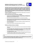
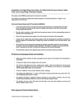
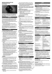
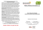
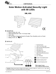
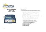
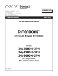
SG-Electrode Operating Instructions and Characteristics 1. Operation The SG-Electrode is designed for continuous monitoring of lead-acid battery electrolyte specific gravity. The measurable range of SG is approximately 1.1 to 1.35. The connections from the electrode are as follows: a. Red wire:- positive supply, 5-24V DC b. Black wire:- negative supply, 0V DC c. White wire:- analog SG output, v ( 1 - 4 volts,). The yellow wire is not connected. Remove the black plastic protective cap and insert the electrode into a battery cell so that the tip of the electrode is immersed in the liquid. Equilibration after initial insertion may typically take up to 10 minutes. The specific gravity can be calculated as follows: SG = 2.09 - 0.31 X v where v is the analog output measured in volts 2. Care and Maintenance Each SG-Electrode contains a polymer membrane in the tip located inside the guard cap. Care should be taken not to damage this membrane with sharp objects. The electrode is designed to be used only in sulfuric acid-water mixtures, i.e. battery acid. Do not immerse the electrode in any other liquids such as solvents, detergents etc otherwise the probe may be damaged. If the unit is to be stored after use, wipe the outside of the electrode with a cloth or tissue to remove any acid adhering to the outside body of the probe and store the probe dry. 3. General Specifications 1. 2. 3. 4. 5. 6. 7. Specific gravity range: 1.08 to 1.35, resolution 0.001 Accuracy: ± 0.015 at 1.30 and ± 0.025 at 1.10 SG units SG-Electrode probe dimensions: 18 mm diameter at tip, 160 mm standard length . Suitable for use in sulfuric acid /water solutions, 50 to 95 wt % water, 5 to 50 oC Equilibration time 5-10 minutes after insertion into cell. Current consumption, (< 25 mA). 5-24V DC power supply. Copyright Electrosense Technologies 2003- 1 4. Operating Characteristics 1.3 13 1.2 12 Voltage Specific Gravity SOLID LINES - BATTERY VOLTAGE OPEN SYMBOLS- SENSOR SG READINGS SOLID SYMBOLS - MANUAL HYDROMETER READINGS VOLTS SG 10 amps 1.1 11 SG SG 40 amps VOLTS VOLTS 20 amps 1.0 0 2 4 6 10 Time (hrs) Figure 1. Fig. 1 shows results of SG measurements obtained using an SG-Electrode installed in a 60 amp hr 12V leadacid battery discharged at a range of currents. Manual hydrometer readings and voltage measurements are shown for comparison. 1.300 \ Sensor response (SG) 1.270 Change in SG from 1.30 to 1.15 1.240 1.210 Change in SG from 1.15 to 1.30 1.180 / 1.150 0.000 5.000 10.000 15.000 20.000 25.000 Time (minutes) Figure 2 Fig. 2 shows the time-dependent response of the SG-Electrode following rapid changes between two watersulfuric acid solutions with a SG of 1.15 and 1.30 respectively. Copyright Electrosense Technologies 2003- 2 Figure 3. Fig. 3 illustrates the influence of electrolyte agitation on specific gravity measurements during discharge and charge of a 60 amp hr lead acid battery at a current of approximately 25 amps. Figure 4. Fig. 4 illustrates standard SG-Electrode. Copyright Electrosense Technologies 2003- 3 5. Calibration of an SG-Electrode supplied with an LCD display. If a display unit (Fig. 5) with direct readout of SG has been provided with the electrode then it is possible to adjust the display to recalibrate the SG-Electrode if the readings have drifted from the true value after a period of use. A sulfuric acid solution of accurately known SG is required for this purpose. Ideally the SG should be no greater than 1.3 and no less than 1.2. Place the electrode in the acid solution and allow it to equilibrate for at least 30 minutes. Turn the screw on the calibration potentiometer shown in Figure 6 until the display shows the correct reading. Fig. 5 shows the direct-reading LCD unit. LCD CONTRAST SCREW SG-ELECTRODE CALIBRATION SCREW Fig. 6 shows the position of the calibration and contrast screws Copyright Electrosense Technologies 2003- 4