1
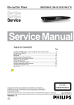
UM0276
User manual
STFPC311 LED Evaluation board
hardware description and user manual
Introduction
The STFPC311-LED is an evaluation board designed for the quick and easy evaluation of
the STFPC311 Vacuum Fluorescent Display Controller used to drive LED (Light Emitting
Diode) displays. Its key features include:
■
One 4-digit, 7-segment LED display
■
Fifteen programmable front panel keys
■
Two switches
■
Four LEDs
■
Two LEDs to display Standby and Mute status respectively
■
One InfraRed Connector for remote control
■
Parallel Port for communication with PC
■
External power supply
■
STFPC311 graphical user interface (GUI) that simulates communication between the
VFD controller and a microcontroller
The Evaluation board package includes:
■
One STFPC311-LED Evaluation board
■
STFPC311 Evaluation software program (GUI)
■
User manual
STFPC311-LED Evaluation board v1.0
April 2007
Rev 2
1/25
www.st.com
www.BDTIC.com/ST
Contents
UM0276
Contents
1
2
Getting started . . . . . . . . . . . . . . . . . . . . . . . . . . . . . . . . . . . . . . . . . . . . . . 4
1.1
Installing the evaluation software . . . . . . . . . . . . . . . . . . . . . . . . . . . . . . . . 4
1.2
Connecting the evaluation board . . . . . . . . . . . . . . . . . . . . . . . . . . . . . . . . 4
Using the evaluation software . . . . . . . . . . . . . . . . . . . . . . . . . . . . . . . . . 5
2.1
WDT and Standby tab . . . . . . . . . . . . . . . . . . . . . . . . . . . . . . . . . . . . . . . . 6
2.2
Command tab . . . . . . . . . . . . . . . . . . . . . . . . . . . . . . . . . . . . . . . . . . . . . . . 7
Display configuration . . . . . . . . . . . . . . . . . . . . . . . . . . . . . . . . . . . . . . . . 7
2.2.2
Write LED ports . . . . . . . . . . . . . . . . . . . . . . . . . . . . . . . . . . . . . . . . . . . . 7
2.2.3
Read switches . . . . . . . . . . . . . . . . . . . . . . . . . . . . . . . . . . . . . . . . . . . . . 7
2.2.4
Setting the Read frequency . . . . . . . . . . . . . . . . . . . . . . . . . . . . . . . . . . . 8
2.2.5
Read RC Data . . . . . . . . . . . . . . . . . . . . . . . . . . . . . . . . . . . . . . . . . . . . . 9
2.2.6
Read front panel keys . . . . . . . . . . . . . . . . . . . . . . . . . . . . . . . . . . . . . . . 9
2.3
Write Display Memory tab . . . . . . . . . . . . . . . . . . . . . . . . . . . . . . . . . . . . . 9
2.4
RC and Hotkeys Config tab . . . . . . . . . . . . . . . . . . . . . . . . . . . . . . . . . . . 10
2.5
3
2.2.1
2.4.1
RC protocol . . . . . . . . . . . . . . . . . . . . . . . . . . . . . . . . . . . . . . . . . . . . . . 10
2.4.2
RC address . . . . . . . . . . . . . . . . . . . . . . . . . . . . . . . . . . . . . . . . . . . . . . 10
2.4.3
RC and hotkey configuration . . . . . . . . . . . . . . . . . . . . . . . . . . . . . . . . . 11
2.4.4
Front panel hotkeys . . . . . . . . . . . . . . . . . . . . . . . . . . . . . . . . . . . . . . . . 11
2.4.5
Front panel hotkey configuration . . . . . . . . . . . . . . . . . . . . . . . . . . . . . . 11
RTC tab . . . . . . . . . . . . . . . . . . . . . . . . . . . . . . . . . . . . . . . . . . . . . . . . . . 12
Revision history . . . . . . . . . . . . . . . . . . . . . . . . . . . . . . . . . . . . . . . . . . . 24
2/25
www.BDTIC.com/ST
UM0276
List of figures
List of figures
Figure 1.
Figure 2.
Figure 3.
Figure 4.
Figure 5.
Figure 6.
Figure 7.
Figure 8.
Figure 9.
Figure 10.
Figure 11.
Figure 12.
Figure 13.
Figure 14.
Figure 15.
Figure 16.
Figure 17.
Figure 18.
Figure 19.
Figure 20.
Figure 21.
Figure 22.
STFPC311-LED Evaluation board layout . . . . . . . . . . . . . . . . . . . . . . . . . . . . . . . . . . . . . . . 4
Parallel port configuration . . . . . . . . . . . . . . . . . . . . . . . . . . . . . . . . . . . . . . . . . . . . . . . . . . 5
READY HIGH selection . . . . . . . . . . . . . . . . . . . . . . . . . . . . . . . . . . . . . . . . . . . . . . . . . . . . 6
Display configuration (ON position) . . . . . . . . . . . . . . . . . . . . . . . . . . . . . . . . . . . . . . . . . . . 7
Write LED Ports and Read Switches . . . . . . . . . . . . . . . . . . . . . . . . . . . . . . . . . . . . . . . . . . 8
Read frequency selection . . . . . . . . . . . . . . . . . . . . . . . . . . . . . . . . . . . . . . . . . . . . . . . . . . 8
LED data display selection . . . . . . . . . . . . . . . . . . . . . . . . . . . . . . . . . . . . . . . . . . . . . . . . . . 9
Remote control and hotkey configuration . . . . . . . . . . . . . . . . . . . . . . . . . . . . . . . . . . . . . 10
Setting the alarm using the RTC . . . . . . . . . . . . . . . . . . . . . . . . . . . . . . . . . . . . . . . . . . . . 12
Reading the RC5 Standby data . . . . . . . . . . . . . . . . . . . . . . . . . . . . . . . . . . . . . . . . . . . . . 13
RC5-based remote control Standby configuration . . . . . . . . . . . . . . . . . . . . . . . . . . . . . . . 14
RC5 protocol Standby key waveform . . . . . . . . . . . . . . . . . . . . . . . . . . . . . . . . . . . . . . . . . 15
Reading the RC6 Standby data . . . . . . . . . . . . . . . . . . . . . . . . . . . . . . . . . . . . . . . . . . . . . 16
RC6-based remote control Standby configuration . . . . . . . . . . . . . . . . . . . . . . . . . . . . . . . 17
Standby Key for RC6 protocol . . . . . . . . . . . . . . . . . . . . . . . . . . . . . . . . . . . . . . . . . . . . . . 17
Reading the NEC remote control key1 data . . . . . . . . . . . . . . . . . . . . . . . . . . . . . . . . . . . . 18
NEC-based remote control Key1 configuration . . . . . . . . . . . . . . . . . . . . . . . . . . . . . . . . . 19
NEC Protocol KEY1 code waveform . . . . . . . . . . . . . . . . . . . . . . . . . . . . . . . . . . . . . . . . . 20
Keys in Bank1 . . . . . . . . . . . . . . . . . . . . . . . . . . . . . . . . . . . . . . . . . . . . . . . . . . . . . . . . . . . 21
Keys in Bank2 . . . . . . . . . . . . . . . . . . . . . . . . . . . . . . . . . . . . . . . . . . . . . . . . . . . . . . . . . . . 21
Keys in Bank3 . . . . . . . . . . . . . . . . . . . . . . . . . . . . . . . . . . . . . . . . . . . . . . . . . . . . . . . . . . . 21
Schematic STFPC311- LED . . . . . . . . . . . . . . . . . . . . . . . . . . . . . . . . . . . . . . . . . . . . . . . . 23
3/25
www.BDTIC.com/ST
Getting started
1
UM0276
Getting started
To start evaluating the STFPC311 Vacuum Fluorescent Display Controller, you must:
●
Install the Evaluation software.
●
Connect the Evaluation Board to the PC running the Evaluation software.
●
Connect an external power supply to the Evaluation Board.
Figure 1.
STFPC311-LED Evaluation board layout
Parallel Cable
LEDs
1.1
Switches
Front Panel Keys IR Sensor
VFD Controller
LED Display
Power Supply
Installing the evaluation software
A ZIP file, “STFPC311_GUI.ZIP”, contains the Evaluation software. This software runs on all
Windows® operating system platforms.
1.
Unzip this file to extract the STFPC311_GUI.exe setup file on the host PC system.
2.
Double-click on the setup file and follow the instructions displayed on the PC screen to
install the software GUI.
Note:
Ensure that the io.dll file included in the ZIP file is extracted to the same folder as the EXE
file.
1.2
Connecting the evaluation board
The Evaluation Board requires an external power supply (supply not included). An
appropriate power supply must have two connectors: one for the 3.3 VDC (reference) supply
and the other for the ground provided on the board (Figure 1).
1.
Connect the parallel cable to the host system.
2.
Plug the external power supply into the board.
4/25
www.BDTIC.com/ST
UM0276
2
Note:
Using the evaluation software
Using the evaluation software
1.
Start the STFPC311_GUI evaluation software application.
2.
Configure the parallel port; open the Settings tab from the main menu and select LPTx
Addr... and enter the correct value as shown in Figure 2. (Default setting is 0378.)
3.
Switch ON the STFPC311 Evaluation Board.
4.
Within 10 seconds after power-on, select the Ready High radio button located on the
WDT and Standby tab (Figure 3). The Standby and Mute LEDs on the board will light
up.
Each time the GUI is invoked, the Ready High radio button is selected by default.
Figure 2.
Parallel port configuration
5/25
www.BDTIC.com/ST
Using the evaluation software
2.1
UM0276
WDT and Standby tab
The WDT and Standby tab enables the user to configure the Watchdog Timeout and
Standby control settings.
In the Watchdog Timer pane, use the Timer Setting pull-down menu to specify the
Watchdog Timer timeout period. Select OFF or a timeout period from 1 to 15 seconds. The
default value is 10 seconds.
Press Reset Timer to reset the Watchdog Timer counter.
The Watchdog Action Setting pane defines the action that takes place when the Watchdog
Timeout expires. Select No Action to do nothing or Issue Standby to switch the VFD
controller into Standby mode.
The STFPC311 continuously monitors the status of the READY pin. Once the READY pin
goes low (Mute LED is OFF on the board), and within the preset timeout period (1s to 15s) it
is not asserted high, the STFPC311 sets the STBY pin to a logic high (STBY LED is OFF on
the board).
Figure 3.
READY HIGH selection
6/25
www.BDTIC.com/ST
UM0276
Using the evaluation software
2.2
Command tab
2.2.1
Display configuration
Select the appropriate dimming settings for the LED display.
The Display Mode (digits and segments) is pre-selected.
Figure 4.
2.2.2
Display configuration (ON position)
Write LED ports
The Write LED Ports pane enables the user to switch ON or OFF the evaluation board
LEDs.
Select the required check boxes (LED1 to LED4) and click Write to switch ON the
corresponding LEDs as shown in the example in Figure 5.
2.2.3
Read switches
The Read Switches button enables the user to read the status of the STFPC311 evaluation
board switches.
Click Read to display the status of switches SW1 and SW2. A green background indicates
that the corresponding switch is closed (ON) as shown in Figure 5.
7/25
www.BDTIC.com/ST
Using the evaluation software
Figure 5.
2.2.4
UM0276
Write LED Ports and Read Switches
Setting the Read frequency
The user can select the time period after which the status of the Front Panel Keys is read.
The same option is also available for RC Data (Figure 6).
Select the correct frequency: Once (default) or every 100ms, 250ms, 500ms or 1000ms.
Figure 6.
Read frequency selection
8/25
www.BDTIC.com/ST
UM0276
2.2.5
Using the evaluation software
Read RC Data
The decoded IR commands are sent to the main processor through the serial interface by
sending 3 bytes of data. The Read RC Data pane represents the 24 bits of these 3-byte data
frames.
2.2.6
Read front panel keys
The Read Front Panel Keys pane enables the user to read the status when the keys on the
evaluation board are pressed. Click the Read Frequency to display the status of keys KS1 to
KS15. A green background indicates that the corresponding key is pressed.
2.3
Write Display Memory tab
The Write Display Memory tab (Figure 7) enables the user to select the data displayed on
the LED display.
From the Set Bits drop-down menu, select the data bit-map to be displayed: Reset, Play,
CH2 or 15:30. Click Send to write the data to the display memory.
Click Toggle Bits to switch bit values in the Display Memory pane, and then click Send to
write the data to the display memory.
Also, the bit-map can be configured by double-clicking the bits in the Display Memory area.
Click Send to write the data to the display memory.
Figure 7.
LED data display selection
9/25
www.BDTIC.com/ST
Using the evaluation software
2.4
UM0276
RC and Hotkeys Config tab
The RC and Hotkeys Config tab is used to configure the remote control and hotkeys as
shown in the example given in Figure 8.
Figure 8.
2.4.1
Remote control and hotkey configuration
RC protocol
The STFPC311 supports three Remote Control (RC) protocols, RC5, RC6, and NEC. (For
more information, see Appendix A on page 13.)
Select the appropriate protocol using radio buttons in the Remote Control Protocol pane.
The RC5 and RC6 protocols use bi-phase modulation Manchester encoding where logic
transitions represent a logic high or logic low signal.
The NEC protocol uses pulse distance bit encoding. A logic ‘1’ takes 2.25 ms to transmit,
while a logic ‘0’ takes only 1.12 ms. A message starts with a 9ms Auto Gain Control (AGC)
burst, which is followed by a 4.5 ms space, which is then followed by the Address and
Command.
The Address and Command are transmitted twice. The second time, all the bits are inverted
and are used to verify the received message.
2.4.2
RC address
The address of the Remote Control unit that will communicate with the STFPC311 must be
specified. Enter the 8 bit values of the protocol address of the Remote Control unit in the text
box of the RC Address pane. For example, the address for the RC5 protocol is 0x00. Table 1
lists the RC protocol address and Standby hotkey configuration values. Double-click on
each of the bits to change its value.
10/25
www.BDTIC.com/ST
UM0276
2.4.3
Using the evaluation software
RC and hotkey configuration
The STFPC311 GUI supports 24 Front Panel Keys, 8 of which may be programmed as RC
hotkeys using check boxes in the RC Hotkeys Configuration pane as shown in Figure 8. For
example, the RC hotkey configuration for Standby mode in RC5 protocol is 0000 1100
(0Ch).
Table 1.
2.4.4
RC protocol address and STANDBY RC hotkey
Protocol
Address
RC hotkey Configuration for STANDBY
RC5
0000 0000 (00h)
0000 1100 (0Ch)
RC6
0010 0111 (27h)
0000 1100 (0Ch)
NEC
0000 0010 (02h)
1000 1000 (88h)
Front panel hotkeys
The Front Panel Hotkeys pane is used to configure hotkeys. Select the correct bank (Bank1,
Bank2 or Bank3) and double-click on each of the bits to change its value. For more
information, see Appendix B on page 21.
2.4.5
Front panel hotkey configuration
The STFPC311 GUI supports 24 Front Panel Keys, 8 of which may be programmed as RC
hotkeys using the RC Hotkey Configuration pane.
The Front Panel Hotkeys pane (Figure 8) shows the settings used to configure the KS15 key
as a hotkey. For more information, see the corresponding Hotkey Configuration section in
Appendix A on page 13.
Example of Hotkey use:
1.
To put the VFD controller in Standby mode, select the Ready Low option in the Standby
Control pane on the WDT and Standby tab.
When the VFD controller is in Standby mode, there are two ways to wake-up the
controller:
2.
a)
Press the remote control Standby key, or
b)
Press the Front Panel hotkey
After the controller wakes up from Standby mode, select the Ready High option in the
Standby Control pane on the WDT and Standby tab within the timeout period,
otherwise the controller switches into Standby mode again.
For more information about how commands are sent, see Section 2.2: Command tab.
11/25
www.BDTIC.com/ST
Using the evaluation software
2.5
UM0276
RTC tab
The Real-Time Clock (RTC) tab (Figure 9) is used to configure the current time and date for
the RTC on the evaluation board. It is also used to configure an Alarm function of the RTC
used to check the interrupt status.
The Time Settings pane displays the current system date and time and provides an interface
for modifying these values. Click Send to store updated values in the RTC registers.
In the Alarm Settings pane, set the date and time to trigger the RTC interrupt. Select Enable
Alarm to enable the interrupt.
Use the Repeat Mode drop-down menu to select the interrupt repetition rate: once per
second, minute, hour, day, month or year. Click Send to store the configuration in the RTC
registers.
The user can specify the frequency at which the RTC interrupt status is to be read using the
Read Frequency pull-down menu in the Status pane. Click Clear IRQ to clear the interrupt.
Note:
The color of IRQ label changes to green when the RTC interrupt is generated.
If the Read Date/Time check box is selected, the Time Settings pane displays the system
time.
Figure 9.
Setting the alarm using the RTC
12/25
www.BDTIC.com/ST
UM0276
Remote control protocols
Appendix A
Remote control protocols
A.1
RC5 protocol
A.1.1
RC5 protocol key interpretation
Figure 10 shows the value in the 3-byte data frame when the RC5 remote control Standby
key is pressed.
The RC key interpretation of these bit values for the 3-byte data frames for the various
STFPC311 protocols is as follows:
Note:
●
A0 to A4: Device Address
●
S: Start bit
●
T: Toggle bit
●
D0 to D5: Key Code Data
●
Others: Stuffed bits (ignored)
See Section 2.4: RC and Hotkeys Config tab on page 10 for more protocol information
Figure 10. Reading the RC5 Standby data
13/25
www.BDTIC.com/ST
Remote control protocols
A.1.2
UM0276
RC5 hotkey configuration
Figure 11 shows the STFPC311 being configured to interface with the RC5 protocol-based
remote control.
The RC5 hotkey addressing for Standby configuration is as follows:
●
RC Address: 0x00
●
Hotkey: Standby (code: 0x0C)
The RC5 protocol uses Bi-phase modulation Manchester encoding in which a low-to-high
transition represents a logic high signal, and a high-to-low transition represents a logic low
signal.
Note:
See Section 2.4: RC and Hotkeys Config tab on page 10 for more protocol information.
Figure 11. RC5-based remote control Standby configuration
14/25
www.BDTIC.com/ST
UM0276
Remote control protocols
Figure 12 shows the signal at the IR sensor output when the RC5 Standby key is pressed.
The output shown is an inversion of the IR signal received by the IR sensor.
Figure 12. RC5 protocol Standby key waveform
A.2
RC6 protocol
A.2.1
RC6 protocol key interpretation
Figure 13 shows the signal at the output of IR sensor when Standby key of RC6 remote
control is pressed.
The RC key interpretation of these bit values for the 3-byte data frames for the various
STFPC311 protocols is as follows:
Note:
●
A0 to A7: device Address
●
S: Start bit
●
T: Toggle bit
●
D0 to D7: Key Code Data
●
Others: Stuffed bits (ignored)
See Section 2.4: RC and Hotkeys Config tab on page 10 for more protocol information.
15/25
www.BDTIC.com/ST
Remote control protocols
UM0276
Figure 13. Reading the RC6 Standby data
A.2.2
RC6 hotkey configuration
Figure 14 shows STFPC311 being configured to interface with the RC 6 protocol-based
remote control.
The RC6 hotkey addressing for the Standby configuration is as follows:
●
RC Address: 0x27
●
Hotkey: Standby (code: 0x0C)
The RC6 protocol uses Bi-phase modulation Manchester encoding in which a low-to-high
transition represents a logic low signal and a high-to-low transition represents a logic high
signal.
Note:
These transitions are the opposite of those in the RC5 protocol.
Note:
See Section 2.4: RC and Hotkeys Config tab on page 10 for more protocol information.
16/25
www.BDTIC.com/ST
UM0276
Remote control protocols
Figure 14. RC6-based remote control Standby configuration
Figure 15 shows the signal at the IR sensor output when the RC6 Standby key is pressed.
The output shown in an inversion of the IR signal by the IR sensor.
Figure 15. Standby Key for RC6 protocol
Address
Mode
LS
Note:
SB
0 0 0
MSB
TR
0
Data
LSB MSB
0 1 0 0 1 1 1 0 0 0 0
LSB
1 1 0 0
LS: Leader Start Pulse
SB: Start Bit
TR: Trailer Bit
17/25
www.BDTIC.com/ST
Remote control protocols
A.3
NEC protocol
A.3.1
NEC protocol key interpretation
UM0276
Figure 16 shows the value of the 3-byte data frame when KEY1 of NEC remote is pressed.
The RC key interpretation of these bit values for the 3-byte data frames for the various
STFPC311 protocols is as follows:
Note:
●
A0 to A7: device Address
●
S: Start bit
●
T: Toggle bit
●
D0 to D7: Key Code Data
●
Others: Stuffed bits (ignored)
See Section 2.4: RC and Hotkeys Config tab on page 10 for more protocol information.
Figure 16. Reading the NEC remote control key1 data
18/25
www.BDTIC.com/ST
UM0276
A.3.2
Remote control protocols
NEC hotkey configuration
Figure 17 shows STFPC311 being configured to interface with NEC protocol-based remote
control.
The NEC hotkey addressing for the Key1 configuration is as follows:
●
RC Address: 0x02
●
Hotkey: Key1 (Code: 0x88)
A command is transmitted only once, even when the key on the remote control remains
pressed. Every 110ms, a repeat code is transmitted for as long as the key remains down.
This repeat code is simply a 9-ms AGC burst, followed by 2.23-ms space and a 560-µs
burst.
Note:
See Section 2.4: RC and Hotkeys Config tab on page 10 for more protocol information.
Figure 17. NEC-based remote control Key1 configuration
19/25
www.BDTIC.com/ST
Remote control protocols
UM0276
Figure 18 shows the signal at the IR sensor output when the NEC remote control Key1 is
pressed. The output shown is an inversion of the IR signal received by the IR sensor.
Figure 18. NEC Protocol KEY1 code waveform
AGC
Burst
Space
Logic1
Logic0
20/25
www.BDTIC.com/ST
UM0276
Front panel key banks
Appendix B
Front panel key banks
STFPC311 has key data memory of size 2x12, which means it can support 24 front panel
hotkeys. These keys are divided into 3 banks of 8 keys each.
Figure 19. Keys in Bank1
LSB
MSB
Figure 20. Keys in Bank2
LSB
MSB
Figure 21. Keys in Bank3
MSB
LSB
Table 2.
Bill of materials (BOM)
#
Qty
Reference / footprint
Value / generic part
number
Description
Manufacturer
1
1
BT1
BAT-2
Berg strip for
battery
Any
2
3
C1, C2, C8
100 nF
Capacitor
Any
3
2
C3, C6, C7
10 pF
Capacitor
Any
4
1
C4
10 nF
Capacitor
Any
5
2
C5, C9
10 µF
Capacitor
Any
6
1
CON1
DB25 - 25 pin male
Connector
Any
7
1
CON2
Header – SIP4
Connector
Any
8
12
D1, D2, D3, D4, D5, D6, D7,
D8, D9, D10, D11, D12
Diode - 0.4
Diode
Any
9
1
JP1
Header HDR1X30
Header
Not mounted
10
1
JP2
HDR6X2
Header
Any
21/25
www.BDTIC.com/ST
Front panel key banks
Table 2.
UM0276
Bill of materials (BOM) (continued)
Qty
Reference / footprint
Value / generic part
number
Description
Manufacturer
11
15
KS1, KS 2, KS 3, KS 4, KS 5,
KS 6, KS 7, KS 8,KS 9, KS 10,
KS 11, KS 12, KS 13, KS 14,
KS 15
Push tact switch
Keys
Any
12
6
LED1, LDE2, LED3, LED4,
Mute, STBY1
SMD
LED
Any
13
1
Q13
SOT-23/BC857B
PNP Transistor
Any
14
13
Q1, Q2, Q3, Q4, Q5, Q6, Q7,
Q8, Q9,
Q10, Q11,Q12
SOT-23/BC547
NPN Transistor
Any
15
6
R1, R10, R2, R3, R4, R5
220 Ω
Resistor
Any
16
1
R11
0Ω
Resistor
Any
17
6
R6, R9,R12, R13, R16, R17
18 kΩ
Resistor
Any
18
1
R14
33 kΩ
Resistor
Any
19
1
R15
100 Ω
Resistor
Any
20
3
R7, R8, R19
10 kΩ
Resistor
Any
21
1
R18
4.7 kΩ
Resistor
Any
22
1
S1
SW-DIP4
DIP switch
Any
23
1
U1
7-SEG-LED
Seven segment
display
Any
24
1
U2
74VHC14TTR
Hex - inverter
ST
25
1
U3
STFPC311BTR
VFD Controller
ST
26
1
U4
74V2G07STR
I2C Buffer
ST
27
1
U5
M41T81M6E
RTC
ST
28
2
X1, X2
Banana socket
Socket
FARNELL 150-040
29
1
Y1
32.768 KHz-BCY-W2/D3.1
Crystal oscillator
Any
#
22/25
www.BDTIC.com/ST
www.BDTIC.com/ST
A
B
C
13
25
12
24
SDA_IN
11
23
10 SPI_DOUT
22
9
21
8
20
SCL
7
19
6 SDA_OUT
18
5 READY
17
4 SPI_STB
16
3 SPI_DIN
15
2 SPI_CLK
14
1
1
2
3
4
2
4
6
8
10
12
Header 6X2
1
3
5
7
9
11
JP2
I2C BUFFER
74V2G07
1A VCC
3Y
1Y
2A
3A
GND 2Y
U4
1
100
R15
1A
1Y
2A
2Y
3A
3Y
GND
R7
10k
R8
10k
VCC3.3V
Front Panel
Keys
R6
18k
14
13
12
11
10
9
8
STBY1
MUTE1
VCC
6A
6Y
5A
5Y
4A
4Y
U2
74VHC14
VCC3.3V
1
2
3
4
5
6
7
I2C_SCL
I2C_SDA
VCC3.3V
CLK
DOUT
STBY
I2C_SDA
I2C_SCL
8
7
6
5
C5
10uF
DIN
DOUT
STB
CLK
Signal and power header Provision
STB
DIN
READY
MUTE
RTC_IRQ
4
SCL
1
SDA_IN
2
SDA_OUT 3
IR Demodulator
F.Header
GND
VCC
NC
OUT
CON2
DB25-M
CON1
LED1
KS1
R16
18k
R11
0
R9
18k
KEY2
KEY1
R17
18k
GND
2
220 STBY
220 MUTE
220 LED1
VCC3.3V
R10
R5
R4
R3
LED3
220 LED2
KS5
LED2
KS2
R2
KS4
LED4
100nF
C1
KS6
LED3
KS3
220
R14
VCC3.3V
100nF
C2
R12 18k
33k
R13 18k
S1
VCC3.3V
KS10
220
KS7
8
7
6
5
1
2
3
4
KS9
R1
KS12
LED4
KS11
VCC3.3V
KS14
D
KS13
2
1
2
3
4
5
6
7
8
9
10
11
12
13
KS15
S1
S2
S3
S4
S5
K1
3
1
2
3
4
5
6
3
OSC
SW1
SW2
MUTE
STBY
VDD
GND
KEY1
KEY2
READY
IRDATA_IN
VEE
VDD
U3
STFPC311
R18
4.7k
3
BC857B
Q13
K4
SEG8
SEG7
K3
K2
SEG6
7-SEG-LED
SEG1
SEG2
SEG3
SEG4
SEG5
K1
U1
12
11
10
9
8
7
K4
S8
S7
K3
K2
S6
LED1
LED2
LED3
LED4
DOUT
DIN
CLK
STB
G(1)
G(2)
G(3)
G(4)
G(5)
52
51
50
49
48
47
46
45
44
43
42
41
40
LED1
LED2
LED3
LED4
DOUT
DIN
CLK
STB
GRID1
GRID2
GRID3
GRID4
GRID5
SEG1/KS1
SEG2/KS2
SEG3/KS3
SEG4/KS4
SEG5/KS5
SEG6/KS6
SEG7/KS7
SEG8/KS8
SEG9/KS9
SEG10/KS10
SEG11/KS11
SEG12/KS12
VEE
14
15
16
17
18
19
20
21
22
23
24
25
26
S/KS(1)
S/KS(2)
S/KS(3)
S/KS(4)
S/KS(5)
S/KS(6)
S/KS(7)
S/KS(8)
S/KS(9)
S/KS(10)
S/KS(11)
S/KS(12)
G(1)
G(2)
G(3)
G(4)
G(5)
G(6)
G(7)
G(8)
S(20)/G(9)
S(19)/G(10)
S(18)/G(11)
RTC_IRQ
1
2
4
BT1
Battery
VBAT
Y1
32.768kHz
C6
10pF
NC
VDD
GRID6
GRID7
GRID8
SEG20/GRID9
SEG19/GRID10
SEG18/GRID11
SEG17/GRID12
SEG16/GRID13
SEG15/GRID14
SEG14/GRID15
SEG13/GRID16
4
C7
10pF
1
2
3
4
VCC
IRQ
SCL
SDA
Real Time Clock
X1
X2
VBAT
GND
U5
M41T81
G(6)
G(7)
G(8)
S(20)/G(9)
S(19)/G(10)
S(18)/G(11)
S(17)/G(12)
S(16)/G(13)
S(15)/G(14)
S(14)/G(15)
S(13)/G(16)
C3
10pF
39
38
37
36
35
34
33
32
31
30
29
28
27
S(14)/G(15)
S(13)/G(16)
S/KS(12)
S/KS(11)
S/KS(10)
S/KS(9)
S/KS(8)
S/KS(7)
S/KS(6)
S/KS(5)
S/KS(4)
S/KS(3)
S/KS(2)
S/KS(1)
D1 S/KS(1)
D2 S/KS(2)
D3 S/KS(3)
D4 S/KS(4)
D5 S/KS(5)
D6 S/KS(6)
D7 S/KS(7)
D8 S/KS(8)
D9 S/KS(9)
D10 S/KS(10)
D11 S/KS(11)
D12 S/KS(12)
1N4148
JP1
S/KS(1)
1
8
7
6
5
C4
10nF
Q1
Q9
S/KS(5)
1
RTC_IRQ
R19
10k
VCC3.3V
G(1) 1
VCC3.3V
5
Q2
BC547
S/KS(3)
1
S/KS(6)
1
5
Q10
Date:
File:
B
Size
Title
Q3
Header 30
C9
10uF
Q4
Q12
S/KS(8)
1
BC547
G(4)1
BC547
Q7
BC547
S/KS(4)
1
BC547
Q8
X2
VCC3.3V
VCC3.3V
Revision
Version0.1
Power Plugs
X1
GND
BC547
VCC3.3V
6
30-Mar-2007
Sheet of
C:\Documents and Settings\deepak pathania\Desktop\STFPC311_LED.DDB
Drawn By: Dicky Kurniawan
Number
6
BC547
Front Panel Board (LED):STFPC311
C8
100nF
VCC3.3V
Q11
S/KS(7)
1
BC547
G(3)1
BC547
LED Grid Driver
Q6
LED Segment Driver
BC547
G(2)1
BC547
Q5
BC547
S/KS(2)
1
LED Segment Driver
Provision to Connect to different LED
2 S5
3
2 S1
3
3 K1
2
2 S6
3
2 S3
3
3 K3
2 S2
3
3 K2
2
2 S7
3
VCC3.3V
1
2
3
4
5
6
7
8
9
10
11
12
13
14
15
16
17
18
19
20
21
22
23
24
25
26
27
28
29
30
G(1)
G(2)
G(3)
G(4)
G(5)
G(6)
G(7)
G(8)
S(20)/G(9)
S(19)/G(10)
S(18)/G(11)
S(17)/G(12)
S(16)/G(13)
S(15)/G(14)
S(14)/G(15)
S(13)/G(16)
S/KS(12)
S/KS(11)
S/KS(10)
S/KS(9)
S/KS(8)
S/KS(7)
S/KS(6)
S/KS(5)
S/KS(4)
S/KS(3)
S/KS(2)
S/KS(1)
2
2 S8
3
2 S4
3
3 K4
SW1
SW2
NC
READY
2
1
A
B
C
D
UM0276
Front panel key banks
Figure 22. Schematic STFPC311- LED
23/25
KS8
Revision history
3
UM0276
Revision history
Table 3.
Revision history
Date
Revision
Changes
31-Aug-2006
1
Initial release
02-Apr-2007
2
Bill of materials (BOM) and Schematic STFPC311- LED added
24/25
www.BDTIC.com/ST
UM0276
Please Read Carefully:
Information in this document is provided solely in connection with ST products. STMicroelectronics NV and its subsidiaries (“ST”) reserve the
right to make changes, corrections, modifications or improvements, to this document, and the products and services described herein at any
time, without notice.
All ST products are sold pursuant to ST’s terms and conditions of sale.
Purchasers are solely responsible for the choice, selection and use of the ST products and services described herein, and ST assumes no
liability whatsoever relating to the choice, selection or use of the ST products and services described herein.
No license, express or implied, by estoppel or otherwise, to any intellectual property rights is granted under this document. If any part of this
document refers to any third party products or services it shall not be deemed a license grant by ST for the use of such third party products
or services, or any intellectual property contained therein or considered as a warranty covering the use in any manner whatsoever of such
third party products or services or any intellectual property contained therein.
UNLESS OTHERWISE SET FORTH IN ST’S TERMS AND CONDITIONS OF SALE ST DISCLAIMS ANY EXPRESS OR IMPLIED
WARRANTY WITH RESPECT TO THE USE AND/OR SALE OF ST PRODUCTS INCLUDING WITHOUT LIMITATION IMPLIED
WARRANTIES OF MERCHANTABILITY, FITNESS FOR A PARTICULAR PURPOSE (AND THEIR EQUIVALENTS UNDER THE LAWS
OF ANY JURISDICTION), OR INFRINGEMENT OF ANY PATENT, COPYRIGHT OR OTHER INTELLECTUAL PROPERTY RIGHT.
UNLESS EXPRESSLY APPROVED IN WRITING BY AN AUTHORIZED ST REPRESENTATIVE, ST PRODUCTS ARE NOT
RECOMMENDED, AUTHORIZED OR WARRANTED FOR USE IN MILITARY, AIR CRAFT, SPACE, LIFE SAVING, OR LIFE SUSTAINING
APPLICATIONS, NOR IN PRODUCTS OR SYSTEMS WHERE FAILURE OR MALFUNCTION MAY RESULT IN PERSONAL INJURY,
DEATH, OR SEVERE PROPERTY OR ENVIRONMENTAL DAMAGE. ST PRODUCTS WHICH ARE NOT SPECIFIED AS "AUTOMOTIVE
GRADE" MAY ONLY BE USED IN AUTOMOTIVE APPLICATIONS AT USER’S OWN RISK.
Resale of ST products with provisions different from the statements and/or technical features set forth in this document shall immediately void
any warranty granted by ST for the ST product or service described herein and shall not create or extend in any manner whatsoever, any
liability of ST.
ST and the ST logo are trademarks or registered trademarks of ST in various countries.
Information in this document supersedes and replaces all information previously supplied.
The ST logo is a registered trademark of STMicroelectronics. All other names are the property of their respective owners.
© 2007 STMicroelectronics - All rights reserved
STMicroelectronics group of companies
Australia - Belgium - Brazil - Canada - China - Czech Republic - Finland - France - Germany - Hong Kong - India - Israel - Italy - Japan Malaysia - Malta - Morocco - Singapore - Spain - Sweden - Switzerland - United Kingdom - United States of America
www.st.com
25/25
www.BDTIC.com/ST