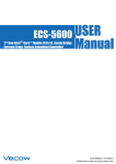
1
ARS-1000 USER
Intel® Atom™ D525 Fanless and Compact
Embedded Controller
Manual
1.0.1 Edition 06/22/2012
All information is subject to change without notice.
Worldwide Technical Support and Product Information
www.vecow.com
Vecow Corporate Headquarters
7F No 105 Zhongcheng Rd Tucheng Dist New Taipei City 23674 Taiwan R.O.C.
Tel: 886 2 2268 5658
Fax: 886 2 2268 1658
For further support information, refer to the Technical Support and Professional Services
appendix. To comment on Vecow Co., Ltd. documentation, refer to the Vecow Co., Ltd.
web site at www.vecow.com.
© 2011–2012 Vecow Co., Ltd. All rights reserved.
Record of Revision
Version
V1.0.0
V1.0.1
Date
April 12 2012
June 22 2012
Page
All
Description
Preliminary Release
Remark
Declaimer
This manual is intended to be used as a practical and informative guide
only and is subject to change without prior notice. It does not represent
commitment from Vecow Co., Ltd. Vecow shall not be liable for direct, indirect,
special, incidental, or consequential damages arising out of the use of the
product or documentation, nor for any infringements upon the rights of third
parties, which may result from such use.
Declaration of Conformity
FCCThis equipment has been tested and found to comply with the limits for a
Class A digital device, pursuant to part 15 of the FCC Rules. These limits are
designed to provide reasonable protection against harmful interference when
the equipment is operated in a commercial environment. This equipment
generates, uses, and can radiate radio frequency energy and, if not installed
and used in accordance with the instruction manual, may cause harmful
interference to radio communications. Operation of this equipment in a
residential area is likely to cause harmful interference in which case the user will
be required to correct the interference at his own expense.
CE
The product(s) described in this manual complies with all applicable European
Union (CE) directives if it has a CE marking. For computer systems to remain CE
compliant, only CE-compliant parts may be used. Maintaining CE compliance
also requires proper cable and cabling techniques.
Copyright and Trademarks
This document contains proprietary information protected by copyright.
All rights are reserved. No part of this document may be reproduced by any
mechanical, electronic, or other means in any form without prior written
permission of the manufacturer. Company/product names mentioned herein
are used for identification
©Vecow ARS-1000 Series Embedded System Series User Manual
iv
Packing List
Item
Description
Qty
1 ARS-1000 Series fanless controller
1
(According to the configuration you order, the ARS-1000 series may contain HDD
and DDR3 SO-DIMM. Please verify these items if necessary.)
2 Accessory box, which contains
• Vecow Drivers & Utilities DVD
1
• Wall-mounting bracket
2
• M4 screws for wall-mounting bracket
4
• 2-pin pluggable terminal block
1
• 3-pin pluggable terminal block
1
1
• SATA HDD and power cable
Order Information
Part Number Description
ARS-1000
Fanless Embedded Controller,
2 LAN, Isolated GPIO (8DI/8DO), 4 COM, 5 USB, Mini PCIe, PCI-104,
One YCB-D15D9 included
ARS-1100
Fanless Embedded Controller,
2 LAN, Isolated GPIO (8DI/8DO), 4 COM, 5 USB, Mini PCIe, 1394a, PC/104+,
One YCB-D15D9 included
ARS-1200
Fanless Embedded controller,
2 LANs, Isolated GPIO (8DI/8DO), 4 COMs, 5 USBs, Mini PCIe, 1394a, CAN, PC/104+,
One YCB-D15D9 included
ARS-1500
Fanless Embedded controller,
2 LANs, Isolated GPIO (8DI/8DO), 8 COMs, 5 USBs, Mini PCIe, PC/104+,
4 YCB-D15D9 included
ARS-1600
Fanless Embedded controller,
2 LANs, Isolated GPIO (8DI/8DO), 8 COMs, 5 USBs, Mini PCIe, PC/104+,
4 YCB-D15D9 included
Optional Accessories
Part Number
VMX-200-4
VMX-200-8
PWA-60WP3
DIN ARS
SCSI-20P-100
TMB-SCSI-20P
YCB-D15D9
Description
4-CH, D1, Real-time, Mini-PCI Express, 120 fps, Video Capture Card, include
cables and SDK
8-CH, D1, Real-time, Mini-PCI Express, 240 fps, Video Capture Card, include
cables and SDK
60W, 24V, 100VAC to 240VAC Power Adapter
Din-Rail Kit for ARS-1000 series
20-pin GPIO 8DI / 8DO Cable, 1M
Terminal Board with One 20-pin Connector and DIN-Rail Mounting
Y Cable from DB15 to Two DB9
v
Table of Contents
Declaimeriv
Declaration of Conformity
iv
Copyright and Trademarks
iv
FCCiv
CEiv
Packing List
Order Information
Optional Accessories
v
v
v
General Introduction
1
1.1 Overview
1.2 Product Specification
1
2
1.2.1 Specification of Vecow ARS-1000
1.2.2 Specification of Vecow ARS-1100
1.2.3 Specification of Vecow ARS-1200
1.2.4 Specification of Vecow ARS-1500
1.2.5 Specification of Vecow ARS-1600
1.2.6 Specification of Optional Video Capture Card-VMX-200-4
1.2.7 Specification of Optional Video Capture Card-VMX-200-8
2
3
4
5
6
7
8
1.3 Mechanical Dimension
9
Hardware Installation
14
2.1 Front Side External I/O Connectors
14
2.1.1 VGA Connector
2.1.2 10/100/1000 Mbps Ethernet Port
2.1.3 GPIO LED Indicator
2.1.4 USB Dual Port
2.1.5 Isolated 8-DI / 8-DO
2.1.6 Reset Tact Switch
14
15
17
17
18
19
2.2 Top Side External I/O Connectors
20
2.3 Main Board Expansion Connectors
24
2.2.1 Remote Power ON / OFF Switch
2.2.2 DC-IN 16~28V Power Terminal Block with Screw Lock
2.2.3 Rotary Switch
2.2.4 Power and HDD LED Indicators
2.2.5 Serial Port COM1 / COM2
2.2.6 Serial Port COM3 / COM4
2.2.6 CFast
20
20
21
22
22
23
23
2.3.1 J2 Additional Power Supply for L2 Board
2.3.2 J5 Miscellaneous Pin Header
2.3.3 CN7, J3 LVDS
2.3.4 CN1, CN4 SATA Connector J1 SATA Power Connector
2.3.5 J4 Internal 2 USB Ports
2.3.6 J6 Audio Connector
2.3.7 CN10 PC/104 plus (PCI)
2.3.8 CN2 PC/104 (ISA)
2.3.9 CN17 Mini-PCIe Connector
2.3.10 Battery
26
27
27
28
29
30
30
31
32
33
vi
2.4 Main Board Jumper Setting
34
2.5 Mounting Options
36
2.4.1 JP1 LVDS Backlight Power Selection
2.4.2 JP2 PCI I/O Voltage Selection
2.4.3 JP3(A) CMOS Clear Jumper Setting
2.4.4 JP3(B) AT/ATX Power mode Jumper Setting
35
35
35
35
2.5.1 Stand Mounting
2.5.2 Wall Mounting
2.5.3 DIN-rail Mounting
36
37
38
BIOS Settings
39
3.1 Main Menu
3.2 Advanced BIOS Features
39
40
3.2.1 IRQ Resource Exclusion
40
3.3 CPU Menu
41
3.4 Security Menu
3.5 Power Menu
3.6 Exit Menu
44
44
45
Software Installation
46
Appendix A GPIO & WDT Function Programming Guide
49
Appendix B LED & Rotary Function Programming Guide
51
3.3.1 CPU Control
3.3.2 ICH Control
3.3.3 LPC Control Sub-Menu
3.3.4 LPC Control -SIO ITE8783F Configuration
41
42
42
43
4.1 Chipset Driver Installation
4.2 Graphic Driver Installation
4.3 Network Device Driver Installation
4.4 Audio Device Driver Installation
4.5 Linux Driver Support
4.6 Additional Drivers
46
47
47
48
48
48
vii
1
General Introduction
1.1 Overview
ARS-1000 series is fanless embedded automation controller
equipped with Intel ® Atom™ D525 1M cache, 1.8GHz
processor, 2 Gigabit Ethernet ports, 3 RS-232 and 1 RS232/422/485, external accessible CFast, 5 USB, Isolated DIO,
Mini PCIe socket, and supports wide range DC-IN 16 to 28 V.
With fanless thermal, compact size, small footprint, and
wide operating temperatures -20 ~ 70°C (-4 ~ 157°F), ARS1000 series provides high performance, high versatility, and
easy to install in field cabinets.
For further expansion, ARS-1000 model supports PCI-104,
ARS-1100 supports 1394a and PC/104+. In addition, ARS1000 series supports programmable GPIO 16-step rotary
switch and 4 mode/status LED displays, in order to provide
more adaptability for various environment requests.
With rich OS and driver supports, such as Windows
XP Embedded, Windows XP Pro, and even Linux, ARS1000 Series are application-ready platforms that provide
multipurpose applications.
ARS-1000 series is value computing platforms for
manufacturing executing systems, factory automation, and
industrial applications.
General Introduction
1
1.2 Product Specification
1.2.1 Specification of Vecow ARS-1000
System Hardware
CPU
Chipset
Memory
Storage
Mini PCIe
Display
Audio
I/O Interface
Serial Ports
LAN
USB 2.0
Programmable GPIO
PCI-104
General
Certifications
Dimensions(W x H x D)
Enclosure
Mounting
Power Requirements
Weight
OS Support
System Design
Environmental
Operating Temperature
Storage Temperature
Humidity
Shock Protection
Vibration Protection
Intel Atom D525, 1M Cache, 1.8GHz Processor
ICH8M
Single Channel Supports 2 DDR3 SO-DIMM, up to 4GB
Internal Two 2.5" SATA/SATA II for HDD/SSD
Outside Accessible CFast Slot
1
Front DB 15 VGA
Internal LVDS 24-bit
Internal Stereo Headphone, Internal Microphone
3 RS-232, 1 RS-232/422/485 wtih Automatic Data Flow Control
2 Intel® GbE WG82583V
Front: 2
Internal: 2
Mini PCIe: 1
Isolation Protection on GPIO-16 (8DI/8DO) Sink/Wet Contact Source
GPIO-4 (Programmable Status/Modes LED Display)
16-step Rotary Switch (States/Modes Select)
PCI-104 Slot, Supports 3.3V & +5V
CF, FCC Class A
186mm x 147mm x 79mm (7.3” x 5.8” x 3.1”)
Aluminum Heat-sink and Sheet Metal Chassis with Iron-gray Color
Wall-mounting for DIN-rail
ATX : 2-pin Remote Power On/Off Switch
AT : Optional by Jumper Setting
On-board DC-to-DC Power Support from 16 ~ 28 V DC
2.1 Kg (4.5 lb)
Windows XP Embedded / Windows XP Pro and Above
Linux Fedora 11 / Ubuntu 10.04 / Cent OS 5.3 / Kernel
Top Cover Heat-sink with Internal Heat Spreader for Fanless Design
-20°C to 70°C (-4°F to 157°F) Ambient Temperature with Air Flow
-40°C to 85°C (-40°F to 185°F)
0% to 95% Humidity, Non-condensing
IEC 68 2-27
CFast: 50G @ Wall-mount, Half Sine, 11ms
HDD: 20G @ Wall-mount, Half Sine, 11ms
IEC 68 2-64 (Random 1 Oct./min, 1hr/axis.)
CFast: 5 Grms @ 5~500Hz,
HDD: 1 Grms @ 5~500Hz
©Vecow ARS-1000 Series Embedded ControllerUser Manual
General Introduction
2
1.2.2 Specification of Vecow ARS-1100
System Hardware
CPU
Chipset
Memory
Storage
Mini PCIe
Display
Audio
I/O Interface
Serial Ports
LAN
USB 2.0
Programmable GPIO
PC/104+
1394a
General
Certifications
Dimensions(W x H x D)
Enclosure
Mounting
Power Requirements
Weight
OS Support
System Design
Environmental
Operating Temperature
Storage Temperature
Humidity
Shock Protection
Vibration Protection
Intel Atom D525, 1M Cache, 1.8GHz Processor
ICH8M
Single Channel Supports 2 DDR3 SO-DIMM, up to 4GB
Internal Two 2.5" SATA/SATA II for HDD/SSD
Outside Accessible CFast Slot
1
Front DB 15 VGA
Internal LVDS 24-bit
Internal Stereo Headphone, Internal Microphone
3 RS-232, 1 RS-232/422/485 wtih Automatic Data Flow Control
2 Intel® GbE WG82583V
Front: 2
Internal: 2
Mini PCIe: 1
Isolation Protection on GPIO-16 (8DI/8DO) Sink/Wet Contact Source
GPIO-4 (Programmable Status/Modes LED Display)
16-step Rotary Switch (States/Modes Select)
PCI-104 Slot, Supports 3.3V & +5V
3 ports
CF, FCC Class A
186mm x 147mm x 79mm (7.3” x 5.8” x 3.1”)
Aluminum Heat-sink and Sheet Metal Chassis with Iron-gray Color
Wall-mounting for DIN-rail
ATX : 2-pin Remote Power On/Off Switch
AT : Optional by Jumper Setting
On-board DC-to-DC Power Support from 16 ~ 28 V DC
2.1 Kg (4.5 lb)
Windows XP Embedded / Windows XP Pro and Above
Top Cover Heat-sink with Internal Heat Spreader for Fanless Design
-20°C to 70°C (-4°F to 157°F) Ambient Temperature with Air Flow
-40°C to 85°C (-40°F to 185°F)
0% to 95% Humidity, Non-condensing
IEC 68 2-27
CFast: 50G @ Wall-mount, Half Sine, 11ms
HDD: 20G @ Wall-mount, Half Sine, 11ms
IEC 68 2-64 (Random 1 Oct./min, 1hr/axis.)
CFast: 5 Grms @ 5~500Hz,
HDD: 1 Grms @ 5~500Hz
General Introduction
3
1.2.3 Specification of Vecow ARS-1200
System Hardware
CPU
Chipset
Memory
Storage
Mini PCIe
PC/104 Slot
Display
Audio
I/O Interface
Serial Ports
LAN
USB 2.0
Programmable GPIO
1394a
CAN
General
Certifications
Dimensions(W x H x D)
Enclosure
Mounting
Power Requirements
Weight
OS Support
System Design
Environmental
Operating Temperature
Storage Temperature
Humidity
Shock Protection
Vibration Protection
Intel Atom D525, 1M Cache, 1.8GHz Processor
ICH8M
Single Channel Supports 2 DDR3 SO-DIMM, up to 4GB
Internal Two 2.5" SATA/SATA II for HDD/SSD
Outside Accessible CFast Slot
1
PC/104+ Slot, Support 3.3V and +5V
Front DB 15 VGA
Internal LVDS 24-bit
Internal Stereo Headphone, Internal Microphone
3 RS-232, 1 RS-232/422/485 wtih Automatic Data Flow Control
2 Intel® GbE WG82583V
Front: 2
Internal: 2
Mini PCIe: 1
Isolation Protection on GPIO-16 (8DI/8DO) Sink/Wet Contact Source
GPIO-4 (Programmable Status/Modes LED Display)
16-step Rotary Switch (States/Modes Select)
3 Ports
2 Ports
CF, FCC Class A
186mm x 147mm x 79mm (7.3” x 5.8” x 3.1”)
Aluminum Heat-sink and Sheet Metal Chassis with Iron-gray Color
Wall-mounting for DIN-rail
ATX : 2-pin Remote Power On/Off Switch
AT : Optional by Jumper Setting
On-board DC-to-DC Power Support from 16 ~ 28 V DC
2.1 Kg (4.5 lb)
Windows XP Embedded / Windows XP Pro and Above
Top Cover Heat-sink with Internal Heat Spreader for Fanless Design
-20°C to 70°C (-4°F to 157°F) Ambient Temperature with Air Flow
-40°C to 85°C (-40°F to 185°F)
0% to 95% Humidity, Non-condensing
IEC 68 2-27
CFast: 50G @ Wall-mount, Half Sine, 11ms
HDD: 20G @ Wall-mount, Half Sine, 11ms
IEC 68 2-64 (Random 1 Oct./min, 1hr/axis.)
CFast: 5 Grms @ 5~500Hz,
HDD: 1 Grms @ 5~500Hz
©Vecow ARS-1000 Series Embedded ControllerUser Manual
General Introduction
4
1.2.4 Specification of Vecow ARS-1500
System Hardware
CPU
Chipset
Memory
Storage
Mini PCIe
PC/104 Slot
Display
Audio
I/O Interface
Serial Ports
LAN
USB 2.0
Programmable GPIO
General
Certifications
Dimensions(W x H x D)
Enclosure
Mounting
Power Requirements
Weight
OS Support
System Design
Environmental
Operating Temperature
Storage Temperature
Humidity
Shock Protection
Vibration Protection
Intel Atom D525, 1M Cache, 1.8GHz Processor
ICH8M
Single Channel Supports 2 DDR3 SO-DIMM, up to 4GB
Internal Two 2.5" SATA/SATA II for HDD/SSD
Outside Accessible CFast Slot
1
PC/104+ Slot, Support 3.3V and +5V
Front DB 15 VGA
Internal LVDS 24-bit
Internal Stereo Headphone, Internal Microphone
3 RS-232, 1 RS-232/422/485 wtih Automatic Data Flow Control
Additional 4 RS-232
2 Intel® GbE WG82583V
Front: 2
Internal: 2
Mini PCIe: 1
Isolation Protection on GPIO-16 (8DI/8DO) Sink/Wet Contact Source
GPIO-4 (Programmable Status/Modes LED Display)
16-step Rotary Switch (States/Modes Select)
CF, FCC Class A
186mm x 147mm x 79mm (7.3” x 5.8” x 3.1”)
Aluminum Heat-sink and Sheet Metal Chassis with Iron-gray Color
Wall-mounting for DIN-rail
ATX : 2-pin Remote Power On/Off Switch
AT : Optional by Jumper Setting
On-board DC-to-DC Power Support from 16 to 28 V DC
2.1 Kg (4.5 lb)
Windows XP Embedded / Windows XP Pro and Above
Top Cover Heat-sink with Internal Heat Spreader for Fanless Design
-20°C to 70°C (-4°F to 157°F) Ambient Temperature with Air Flow
-40°C to 85°C (-40°F to 185°F)
0% to 95% Humidity, Non-condensing
IEC 68 2-27
CFast: 50G @ Wall-mount, Half Sine, 11ms
HDD: 20G @ Wall-mount, Half Sine, 11ms
IEC 68 2-64 (Random 1 Oct./min, 1hr/axis.)
CFast: 5 Grms @ 5~500Hz,
HDD: 1 Grms @ 5~500Hz
General Introduction
5
1.2.5 Specification of Vecow ARS-1600
System Hardware
CPU
Chipset
Memory
Storage
Mini PCIe
PC/104 Slot
Display
Audio
I/O Interface
Serial Ports
LAN
USB 2.0
Programmable GPIO
CAN
General
Certifications
Dimensions(W x H x D)
Enclosure
Mounting
Power Requirements
Weight
OS Support
System Design
Environmental
Operating Temperature
Storage Temperature
Humidity
Shock Protection
Vibration Protection
Intel Atom D525, 1M Cache, 1.8GHz Processor
ICH8M
Single Channel Supports 2 DDR3 SO-DIMM, up to 4GB
Internal Two 2.5" SATA/SATA II for HDD/SSD
Outside Accessible CFast Slot
1
PC/104+ Slot, Support 3.3V and +5V
Front DB 15 VGA
Internal LVDS 24-bit
Internal Stereo Headphone, Internal Microphone
3 RS-232, 1 RS-232/422/485 wtih Automatic Data Flow Control
additional 4 RS-232
2 Intel® GbE WG82583V
Front: 2
Internal: 2
Mini PCIe: 1
Isolation Protection on GPIO-16 (8DI/8DO) Sink/Wet Contact Source
GPIO-4 (Programmable Status/Modes LED Display)
16-step Rotary Switch (States/Modes Select)
2 Ports
CF, FCC Class A
186mm x 147mm x 79mm (7.3” x 5.8” x 3.1”)
Aluminum Heat-sink and Sheet Metal Chassis with Iron-gray Color
Wall-mounting for DIN-rail
ATX : 2-pin Remote Power On/Off Switch
AT : Optional by Jumper Setting
On-board DC-to-DC Power Support from 16 ~ 28 V DC
2.1 Kg (4.5 lb)
Windows XP Embedded / Windows XP Pro and Above
Top Cover Heat-sink with Internal Heat Spreader for Fanless Design
-20°C to 70°C (-4°F to 157°F) Ambient Temperature with Air Flow
-40°C to 85°C (-40°F to 185°F)
0% to 95% Humidity, Non-condensing
IEC 68 2-27
CFast: 50G @ Wall-mount, Half Sine, 11ms
HDD: 20G @ Wall-mount, Half Sine, 11ms
IEC 68 2-64 (Random 1 Oct./min, 1hr/axis.)
CFast: 5 Grms @ 5~500Hz,
HDD: 1 Grms @ 5~500Hz
©Vecow ARS-1000 Series Embedded ControllerUser Manual
General Introduction
6
1.2.6 Specification of Optional Video Capture Card-VMX-200-4
General
Bus Type / Form Factor
Dimensions (L x H)
I/O connector
Environment Certification
Storage Temperature
Operate Temperature
Video
Maximum Channel Number
Input Connector
Resolution
Recording Rate
Video Compression Format
Audio
Maximum Channel Number
Audio Input Connector
Software
OS Support
SDK
Recommend System
CPU
Memory
Graphics Unit
Storage Size
Mini PCI Express
51mm x 30mm (2.0" x 1.2")
1x 16 pin headers to D-Sub 15 cables
1x D-Sub 15 to BNC cable
FCC, CE, RoHS Compliance
-40°C to 85°C
0°C to 60°C
4
4 input BNC to D-Sub 15
D1 (NTSC: 720 x 480 / PAL: 720 x 576)
CIF (NTSC: 360 x 240 / PAL: 360 x 288)
4CIF (NTSC: 704 x 480 / PAL: 704 x 576)
DCIF (NTSC: 528 x 320 / PAL: 528 x 384)
QCIF (NTSC: 180 x 120 / PAL: 180 x 144)
4CH with full D1 resolution
120 fps on NTSC system, 100 fps on PAL system
H.264 / MJPEG
4 mono or 2 stereo
4 input RCA to D-Sub 15
WindowsXP/VISTA/Windows7 (32 Bits or 64 Bits)
Standard Linux kernel 2.6.32 and all above
VC++ / .NET
Intel Core 2 Duo E4500 2.2GHz
1GB
DirectX 9.0c compatible display card
500GB
General Introduction
7
1.2.7 Specification of Optional Video Capture Card-VMX-200-8
General
Bus Type / Form Factor
Dimensions (L x H)
I/O connector
Environment Certification
Storage Temperature
Operate Temperature
Video
Maximum Channel Number
Input Connector
Resolution
Recording Rate
Video Compression Format
Audio
Maximum Channel Number
Audio Input Connector
Software
OS Support
SDK
Recommend System
CPU
Memory
Graphics Unit
Storage Size
Mini PCI Express
51mm x 30mm (2.0" x 1.2")
2x 16 pin headers to D-Sub 15 cables
2x D-Sub 15 to BNC cable
FCC, CE, RoHS Compliance
-40°C to 85°C
0°C to 60°C
8
2x 4 input BNC to D-Sub 15
D1 (NTSC: 720 x 480 / PAL: 720 x 576)
CIF (NTSC: 360 x 240 / PAL: 360 x 288)
4CIF (NTSC: 704 x 480 / PAL: 704 x 576)
DCIF (NTSC: 528 x 320 / PAL: 528 x 384)
QCIF (NTSC: 180 x 120 / PAL: 180 x 144)
8CH with full D1 resolution
240 fps on NTSC system, 100 fps on PAL system
H.264 / MJPEG
8 mono or 2 stereo
2x 4 input RCA to D-Sub 15
WindowsXP/VISTA/Windows7 (32 Bits or 64 Bits)
Standard Linux kernel 2.6.32 and all above
VC++ / .NET
Intel Core 2 Quad Q8400 2.66GHz
1GB
DirectX 9.0c compatible display card
750GB
©Vecow ARS-1000 Series Embedded ControllerUser Manual
General Introduction
8
1.3 Mechanical Dimension
ARS-1000 Model Dimension
Unit : mm (inch)
General Introduction
9
ARS-1100 Model Dimension
Unit : mm (inch)
©Vecow ARS-1000 Series Embedded ControllerUser Manual
General Introduction
10
ARS-1200 Model Dimension
Unit : mm (inch)
General Introduction
11
ARS-1500 Model Dimension
Unit : mm (inch)
©Vecow ARS-1000 Series Embedded ControllerUser Manual
General Introduction
12
ARS-1600 Model Dimension
Unit : mm (inch)
General Introduction
13
2
Hardware Installation
Be careful when handling the unit. When the unit is
plugged in, the internal components generate heat, and
consequently the outer casing may feel hot to the touch.
2.1 Front Side External I/O Connectors
ARS-1000
ARS-1100
2.1.1 VGA Connector
The ARS-1000 comes with a DB15 female connector on
the front panel to connect a VGA monitor. To ensure that
the monitor image remains clear, be sure to tighten the
monitor cable after connecting it to the ARS-1000. The pin
assignments of the VGA connector are shown below.
©Vecow ARS-1000 Series Embedded System Series User Manual
Hardware Installation
14
R
NM
NR
N
S
NN
VGAA1
Pin No.
1
2
3
4
5
6
7
8
9
10
11
12
13
14
15
Description
Red Color Signal
Green Color Signal
Blue Color Signal
NC
Ground
VGA Detect
Ground
Ground
VCC
Ground
NC
DDC-DATA
H-Sync.
V-Sync.
DDC-CLK
2.1.2 10/100/1000 Mbps Ethernet Port
The 10/100/1000 Mbps Ethernet LAN ports 1 and 2 use
8-pin RJ-45 connector. LAN1 and LAN2 are equipped with
Intel 82583V. Using suitable RJ-45 cable, you can connect
ARS-1000 system to a computer, or to any other piece of
equipment that has an Ethernet connection, for example,
a hub or a switch. Moreover, both of them have Wake-onLAN and Preboot Execution Environment capabilities. The
following diagram shows the pinouts for LAN1 and LAN2
port.
Hardware Installation
15
Pin No.
1
2
3
4
5
6
7
8
10 / 100 Mbps
E_TX+
E_TXE_RX+
----------E_RX-----------
1000 Mbps
MDI0_P
MDI0_N
MDI1_P
MDI2_P
MDI2_N
MDI1_N
MDI3_P
MDI3_N
The Ethernet ports use standard RJ-45 jack connectors with
LED indicators on the front side to show Active/Link status
and Speed status.
The LED indicators on the right bottom corners glow a
solid green color when the cable is properly connected to
a 100 Mbps Ethernet network. The LED indicator on the left
bottom corner will flash on and off when Ethernet packets
are being transmitted or received.
The LED indicators on the right bottom corners glow a
solid orange color when the cable is properly connected
to a 1000 Mbps Ethernet network. The LED indicator on
the left bottom corner will flash on and off when Ethernet
packets are being transmitted or received.
N==================
U
LED
Right
bottom
LED
Left
bottom
LED
©Vecow ARS-1000 Series Embedded System Series User Manual
10 Mbps
100 Mbps
1000 Mbps
Off
Solid Green
Solid Orange
Flash Yellow
Flash Yellow
Flash Yellow
Hardware Installation
16
2.1.3 GPIO LED Indicator
The ARS-1000 offers 4 programmable LEDs on front panel.
If the LED is on, it indicates that the mapping SIO GPIO
pin is logic high level. If the LED is off, it indicates that the
mapping SIO GPIO pin is logic low level.
Definition
Programmable LDE1
Programmable LDE2
Programmable LDE3
Programmable LDE4
Mapping to SIO GPIO Function
SIO_GP64
SIO_GP65
SIO_GP66
SIO_GP67
2.1.4 USB Dual Port
The ARS-1000 comes with 2 USB 2.0 hosts on the front
panel. The USB interface supports Plug and Play, which
enables you to connect or disconnect a device whenever
you want, without turning off the system. The hosts can
be used for an external flash disk or hard drive for storing
large amounts of data. You can also use these USB hosts to
connect to a keyboard or a mouse. The following diagram
shows the pinouts for USB1 and USB2 port.
1
Pin No.
1
2
3
4
2
USB1
+5V
USB1USB1+
GND
3
4
USB2
+5V
USB2USB2+
GND
Hardware Installation
17
2.1.5 Isolated 8-DI / 8-DO
The ARS-1000 offers a 16-bit DIO (8-DI / 8-DO) connector.
Each bit of DI and DO equipped with a photo-coupler
for isolated protection. A power buffer device TPD2007F
integrated in 8-DO circuit for motors, solenoids, and lamp
driver applications.
Mapping to SIO GPIO Function
Pin No. Definition
1
INPUT0
SIO_GPI50
2
INPUT 1
SIO_GPI51
3
INPUT 2
SIO_GPI52
4
INPUT 3
SIO_GPI53
5
INPUT 4
SIO_GPI54
6
INPUT 5
SIO_GPI55
7
INPUT 6
SIO_GPI56
8
INPUT 7
SIO_GPI57
9
DI_COM
10
GND
11
OUTPUT0
SIO_GPO20
12
OUTPUT 1
SIO_GPO21
13
OUTPUT 2
SIO_GPO22
14
OUTPUT 3
SIO_GPO23
15
OUTPUT 4
SIO_GPO24
16
OUTPUT 5
SIO_GPO25
17
OUTPUT 6
SIO_GPO26
18
OUTPUT 7
SIO_GPO27
19
N.C.
20
External 24VDC Input
GPI SINK Mode
Isolated GPI input circuit in SINK mode (NPN) is illustrated
as follows.
©Vecow ARS-1000 Series Embedded System Series User Manual
Hardware Installation
18
GPI SOURCE Mode
Digital GPI input signal circuit in SOURCE mode (PNP) is
illustrated as follow:
GPO SINK Mode:
Digital GPO output circuit in SINK mode (NPN) is illustrated
below.
2.1.6 Reset Tact Switch
Use this switch to reset the system without turning off the
power. Momentarily pressing the switch will activate a reset.
Hardware Installation
19
2.2 Top Side External I/O Connectors
2.2.1 Remote Power ON / OFF Switch
It is a 2-pin power-on or power-off switch through Phoenix
Contact terminal block. You could turn on or off the system
power by using this contact. This terminal block support
dual function of soft power-on / power-off (instant off or
delay 4 second), and suspend mode.
2.2.2 DC-IN 16~28V Power Terminal Block with Screw Lock
The ARS-1000 offers 16 to 28 VDC power input with the
terminal block. If the power is supplied properly, the Power
LED will light up a solid green.
Grounding and write routing help limit the effects of noise
due to EMI. Run the ground connection from the ground
screw to the grounding surface prior to connecting the
power.
See the figure shown below for the location of the earth
ground on the terminal block power connector. Connect
the earth ground wire to an appropriate grounded metal
surface.
©Vecow ARS-1000 Series Embedded System Series User Manual
Hardware Installation
20
2.2.3 Rotary Switch
The rotary switch is for board number switch. If there are
more than on ARS-1000 install in the group, it is necessary
to specify the ID for each board respectively by configuring
the rotary switch.
Mapping to SIO GPIO Function
Item
SIO_GP60 SIO_GP61 SIO_GP62 SIO_GP63
Rotary
Switch
1
2
4
8
Position
GND
C
●
0
●
●
1
●
●
2
●
●
●
3
●
●
4
●
●
●
5
●
●
●
6
●
●
●
●
7
●
●
8
●
●
●
9
●
●
●
A
●
●
●
●
B
●
●
●
C
●
●
●
●
D
●
●
●
●
E
●
●
●
●
●
F
Note: "●"connecting to common mode connection (GND)
Hardware Installation
21
2.2.4 Power and HDD LED Indicators
Yellow-HDD LED : A hard disk / CFast LED. If the LED is on,
it indicates that the system’s storage is functional. If it is off,
it indicates that the system’s storage is not functional. If it is
flashing, it indicates data access activities.
Green-Power LED : If the LED is solid green, it indicates that
the system is powered on.
2.2.5 Serial Port COM1 / COM2
Serial ports 1 and 2 have combined in a male DB15
connector and port 2 can be configured for RS-232, RS-422,
or RS-485 with auto flow control communication. Serial Port
2 default setting is RS-232, if you want to use RS-422 or RS485, you can find the setting in BIOS . You can use the Y-type
cable to convert the 15-pin D-Sub connector into two 9-pin
D-Sub connectors to connect both COM1 and COM2 at the
same time. The pin assignments are shown in the following
table:
Serial Port Pin No.
1
2
3
4
5
1
6
7
8
9
10
11
12
13
2
14
15
©Vecow ARS-1000 Series Embedded System Series User Manual
RS-232
DCD
RXD
TXD
DTR
GND
DSR
RTS
CTS
RI
----RXD
TXD
RTS
CTS
GND
RS-422 (4-Wire)
----------------------------------------RXD+
422-RXD422-TXD+
422-TXDGND
RS-485 (2-Wire)
------------------------------------------------DATA+
DATAGND
Hardware Installation
22
2.2.6 Serial Port COM3 / COM4
Serial ports 3 and 4 have combined in a male DB15
connector. You can use the Y-type cable to convert the 15pin D-Sub connector into two 9-pin D-Sub connectors to
connect both COM3 and COM4 at the same time. The pin
assignments are shown in the following table:
Serial Port Pin No.
1
2
3
4
5
3
6
7
8
9
10
11
12
13
4
14
15
Definition
DCD
RXD
TXD
DTR
GND
DSR
RTS
CTS
RI
----RXD
TXD
RTS
CTS
GND
2.2.6 CFast
The ARS-1000 system comes with a CFast socket. Be sure
to disconnect the power source and unscrew the CFast
socket cover before installing a CFast card. The ARS-1000
does not support the CFast hot swap and PnP (Plug and
Play) functions. It is necessary to remove power source first
before inserting or removing the CFast card. The following
table shows the pinouts for CFast port:
Hardware Installation
23
Pin No.
S1
S2
S3
S4
S5
S6
S7
PC1
PC2
PC3
PC4
PC5
PC6
PC7
PC8
PC9
PC10
PC11
PC12
PC13
PC14
PC15
PC16
PC17
Definition
GND
SATA_TX_P2
SATA_TX_N2
GND
SATA_RX_N2
SATA_RX_P2
GND
NC
GND
NC
NC
NC
NC
GND
NC
CFAST_LED_N
NC
NC
NC
+3.3V
+3.3V
GND
GND
NC
2.3 Main Board Expansion Connectors
Block Diagram
The block diagram depicts the relationships among the
interfaces or modules on the main board. Please refer to the
following figure for the main board’s layout design.
©Vecow ARS-1000 Series Embedded System Series User Manual
Hardware Installation
24
The figure below is the top view of the ARS-1000 main
board which is the main board used in the ARS-1000 Series
system. It shows the location of the connectors.
Hardware Installation
25
The figure below is the bottom view of the ARS-1000 main
board.
2.3.1 J2 Additional Power Supply for L2 Board
This 3-pin wafer is not a FAN using connector. J2 is
identical to power DC input connector J5, and reserved for
applying more power rail option in ARS-1100 Layer 2 board
application.
Pin No.
Definition
1
FRAME GND
2
GND
3
VIN (DC 16V ~ 28V)
©Vecow ARS-1000 Series Embedded System Series User Manual
Hardware Installation
26
2.3.2 J5 Miscellaneous Pin Header
These pin headers can be used as a backup for the following
functions: hard drive LED indicator, reset button, power LED
indicator, and power-on/off button. The front and top panel
already provides access to these functions. The following
table shows the pinouts for Miscellaneous port
Group
Pin No.
Definition
1
HDLED
HDD LED
3
HD_LED_N
5
FP_RST_BTN_N
Reset Button
7
GND
2
PWRLED
Power LED
4
PWROK_100MS_N
6
FP_PWR_BTN_N
Power Button
8
GND
2.3.3 CN7, J3 LVDS
CN7
The ARS-1000 supports single-channel 24-bit LVDS Panel
up to 1366x768 pixels panel resolution.
Pin No.
Definition
1
LDDC_CLK
2
LDDC_DATA
3
PANEL1_VDD
4
LA_CN_DATA0_P
5
LA_CN_DATA3_P
6
LA_CN_DATA0_N
7
LA_CN_DATA3_N
8
PANEL1_VDD
9
GND
10
LA_CN_DATA1_P
11
LA_CN_CLKP
12
LA_CN_DATA1_N
Hardware Installation
27
13
14
15
16
17
18
19
20
LA_CN_CLKN
GND
GND
PANEL1_BACKLIGHT
LA_CN_DATA2_P
PANEL1_BACKLIGHT
LA_CN_DATA2_N
GND
J3
The LCD inverter is connected to J3 via a JST 7-pin, 2.5mm
connector to provide +5V/+12V power to the LCD display.
Pin No.
Definition
1
+5V
2
+12V
3
+12V
4
LBKLT_CTL
5
GND
6
GND
7
LBKLT_EN
2.3.4 CN1, CN4 SATA Connector J1 SATA Power Connector
CN1
CN4
©Vecow ARS-1000 Series Embedded System Series User Manual
Hardware Installation
28
The ARS-1000 features two high performance Serial ATA
interfaces that eases cabling to hard drives or SSD with
thin and short cables while application need larger storage
capacity.
Pin No.
Definition
1
GND
2
TXP
3
TXN
4
GND
5
RXN
6
RXP
7
GND
J1
The ARS-1000 also equipped one SATA power connector. It
supply 5V (2A max.) and 12V (1A max) current to the hard
drive or SSD.
Pin No.
Definition
1
+12V
2
GND
3
GND
4
+5V
2.3.5 J4 Internal 2 USB Ports
The ARS-1000 main board provides up to two expansion
USB ports using Plug and Play for Dongle Key or LCD touch
Panel. The USB interface supports 480 Mbps transfer rate
which comply with high speed USB specification Rev. 2.0,
and are fuse protected.
The USB interface is accessed through one 1x6-pin JST
2.0mm connector. You will need an adapter cable if you use
a standard USB connector. The adapter cable has a 1x6-pin
connector on one end and a USB connector on the other.
Pin No.
1
3
5
Description
USB_VCC
USBD2+
USBD3+
Pin No.
2
4
6
Description
USBD2USBD3GND
Hardware Installation
29
2.3.6 J6 Audio Connector
J6
The ARS-1000 offers stereo audio ports by a 2x3 2.0mm pin
header of MIC and Line_Out. The audio chip controller is by
ALC892 which is compliant with the Intel Azalia standard.
To utilize the audio function in Windows, you need to
install corresponding drivers for both Intel ICH8M chipset
and Realtek ALC892 codec. Please refer to Section 4 for
information of driver installation.
Pin No.
Description
Pin No.
Description
1
MIC_OUT_L
2
FRONT_OUT_L
3
MIC_OUT_R
4
FRONT_OUT_R
5
GND
6
GND
2.3.7 CN10 PC/104 plus (PCI)
CN10
This PCI bus connector is a 4x30 (120-pin) 2mm pitch
stackthrough connector as opposed to the 123-pin edge
connector on standard 32-bit PCI Local Bus. This 120-pin
PCI does not support 64-bit extensions, JTAG, PRSNT, or
CLKRUN signals.
The ARS-1000 stackthrough PCI connector supports 4
arbitration (bus master) and 4 request interrupts.
J3/P3
Pin No.
A
B
C
D
1
GND
+5V_SB
+5V
AD00
2
VI/O
AD02
AD01
+5V
3
AD05
GND
AD04
AD03
4
C/BE0#
AD07
GND
AD06
©Vecow ARS-1000 Series Embedded System Series User Manual
Hardware Installation
30
5
6
7
8
9
10
11
12
13
14
15
16
17
18
19
20
21
22
23
24
25
26
27
28
29
30
GND
AD11
AD14
+3.3V
SERR#
GND
STOP#
+3.3V
FRAME#
GND
AD18
AD21
+3.3V
IDSEL0
AD24
GND
AD29
+5V
REQ0#
GND
GNT1#
+5V
CLK2
GND
+12V
-12V
AD09
VI/O
AD13
C/B#1#
GND
PERR#
+3.3V
TRDY#
GND
AD16
+3.3V
AD20
AD23
GND
C/BE3#
AD26
+5V
AD30
GND
REQ2#
VI/O
CLK0
+5V
INTD#
INTA#
REQ3#
AD08
AD10
GND
AD15
PSON#
+3.3V
LOCK#
GND
IRDY#
+3.3V
AD17
GND
AD22
IDSELI
VI/O
AD25
AD28
GND
REQ1#
+5V
GNT2#
GND
CLK3
+5V
INTB#
GNT3#
GND
M66EN
AD12
+3.3V
PAR
PME#
GND
DEVSEL#
+3.3V
C/BE2#
GND
AD19
+3.3V
IDSEL2
IDSEL3
GND
AD27
AD31
VI/O
GNT0#
GND
CLK1
GND
RST#
INTC#
GND
2.3.8 CN2 PC/104 (ISA)
CN10
Hardware Installation
31
The ARS-1000 equipped with IT8888G for ISA 8-bit / 16-bit
application in board layer 2.
Pin No.
1
2
3
4
5
6
7
8
9
10
11
12
13
14
15
16
17
18
19
20
21
22
23
24
25
26
27
28
29
30
31
32
J1/P1
Row A
IOCHK3
SD7
SD6
SD5
SD4
SD3
SD2
SD1
SD0
IOCHRDY
AEN
SA19
SA18
SA17
SA16
SA15
SA14
SA13
SA12
SA11
SA10
SA9
SA8
SA7
SA6
SA5
SA4
SA3
SA2
SA1
SA0
GND
Row B
GND
RESET
+5V
IRQ9
-5V
DRQ2
-12V
SRDY
+12V
KEY
SMEMW
SMEMR
IOW
IOr
DACK3
DRQ3
DACK1
DRQ1
REFRESH
BCLK
IRQ7
IRQ6
IRQ5
IRQ4
IRQ3
DACK2
TC
BALE
+5V
OSC
GND
GND
Pin No.
0
1
2
3
4
5
6
7
8
9
10
11
12
13
14
15
16
17
18
19
J2/P2
Row D
GND
MEMCS16
IOCS16
IRQ10
IRQ11
IRQ12
IRQ15
IRQ14
DACK0
DRQ0
DACK5
DRQ5
DACK6
DRQ6
DACK7
DRQ7
+5V
MASTER16
GND
GND
Row C
GND
SBHE
LA23
LA22
LA21
LA20
LA19
LA18
LA17
MEMR
MEMW
SD8
SD9
SD10
SD11
SD12
SD13
SD14
SD15
KEY
2.3.9 CN17 Mini-PCIe Connector
CN17
©Vecow ARS-1000 Series Embedded System Series User Manual
Hardware Installation
32
It is for connecting any Mini-PCIe adapter such as a Wi-Fi
module.
Pin No. Signal Name
Pin No.
Signal Name
51
Reserved
52
+3.3V
49
Reserved
50
GND
47
Reserved
48
+1.5V
45
Reserved
46
Reserved
43
Reserved
44
Reserved
41
Reserved
42
Reserved
39
Reserved
40
GND
37
Reserved
38
USB_D+
35
GND
36
USB_D33
PETp0
34
GND
31
PETn0
32
SMB_DATA
29
GND
30
SMB_CLK
27
GND
28
+1.5V
25
PERp0
26
GND
23
PERn0
24
+3.3Vaux
21
GND
22
PERST#
19
Reserved (UIM_C4) 20
ENABLE
17
Reserved (UIM_C8) 18
GND
Mechanical Key
15
GND
16
Reserved
13
REFCLK+
14
Reserved
11
REFCLK12
Reserved
9
GND
10
Reserved
7
CLKREQ#
8
Reserved
5
Reserved
6
1.5V
3
Reserved
4
GND
1
WAKE#
2
3.3V
2.3.10 Battery
Battery
The ARS-1000’s real-time clock is powered by a lithium
battery. It is equipped with Panasonic BR2032 190mAh
lithium battery. It is recommended that you not replace
the lithium battery on your own. If the battery needs to be
changed, please contact the Vecow RMA service team.
Hardware Installation
33
2.4 Main Board Jumper Setting
The figure below is the top view of the ARS-1000 main
board which is the main board used in the ARS-1000 Series
system. It shows the location of the jumpers.
You may configure your card to match the needs of your
application by setting jumpers. A jumper is a metal bridge
used to close an electric circuit. It consists of two metal
pins and a small metal clip (often protected by a plastic
cover) that slides over the pins to connect them. To “close”
a jumper, you connect the pins with the clip. To “open”
a jumper, you remove the clip. Sometimes a jumper will
have three pins, labeled 1, 2 and 3. In this case you would
connect either pins 1 and 2, or 2 and 3.
©Vecow ARS-1000 Series Embedded System Series User Manual
Hardware Installation
34
2.4.1 JP1 LVDS Backlight Power Selection
JP1 provides LVDS voltage selection function, closing Pin 1,
2 is for 3.3V LVDS power input; closing Pin 2, 3 is for 5V LVDS
power input.
Setting
Description
1-2
+3.3V (Default)
2-3
+5V
2.4.2 JP2 PCI I/O Voltage Selection
The PCI host board will always determine the PCI signaling
level on the bus by setting all VIO pins to either 3.3V or 5V.
If VIO is set to 3.3V, the system will use 3.3V I/O signaling,
likewise, if VIO is set to 5V, the system will use 5V I/O
signaling. Some PCI host modules may only allow one of
the options, while others may provide a jumper to allow the
user to select the signaling level. Once the signaling level is
selected, the remaining boards in the system must use that
signaling level.
Setting
Description
1-2
+3.3V (Default)
2-3
+5V
2.4.3 JP3(A) CMOS Clear Jumper Setting
Setting
1-3
3-5
Description
Normal (Default)
Clear CMOS
2.4.4 JP3(B) AT/ATX Power mode Jumper Setting
The ARS-1000 main board contains a jumper that can
switch the AT/ATX Power Setting. Normally this jumper
should be set with Pin 4 and Pin 6 in ATX power mode. And
power on the system by the 2-pin terminal block at the top
panel.
If you set it with Pin 2 and Pin 4 in AT power mode. It will
send the power button signal to power on the system
automatically.
Setting
2-4
4-6
Description
AT Mode
ATX Mode (Default)
Hardware Installation
35
2.5 Mounting Options
2.5.1 Stand Mounting
Figure 2.5.1 Stand Mounting
Figure 2.5.2 Stand Mounting Dimension
©Vecow ARS-1000 Series Embedded System Series User Manual
Hardware Installation
36
2.5.2 Wall Mounting
Figure 2.5.3 Wall Mounting
Figure 2.5.4 Wall Mounting Dimension
Hardware Installation
37
2.5.3 DIN-rail Mounting
Figure 2.5.5 DIN-rail Mounting
Figure 2.5.6 DIN-rail Mounting Dimension
©Vecow ARS-1000 Series Embedded System Series User Manual
Hardware Installation
38
3
BIOS Settings
The board uses UEFI BIOS that is use Serial Peripheral
Interface (SPI) Flash. The SPI Flash contains the BIOS Setup
program, POST, the PCI auto-configuration utility, LAN,
EEPROM information, and Serial port support. The BIOS
Setup program is accessed by pressing the <F2> key after
the Power-On Self-Test (POST) memory test begins and
before the operating system boot begins.
The menu bar is shown below.
Main Advanced Intel
Security
Power
Boot
Exit
3.1 Main Menu
System Time / Date : Press “TAB” key to switch sub-items of
value .Then press “ +” key or “-“ key number key for modify
value.
SATA Port 1 / 2 / 3 : Show Current Storage on SATA port.
BIOS Settings
39
3.2 Advanced BIOS Features
Legacy USB Support : Some USB device need active this
function.
3.2.1 IRQ Resource Exclusion
For IRQ 3,4,5,7,9,10,11 , you can select “Reverse” or
“Available” for you PCI/ISA device
©Vecow ARS-1000 Series Embedded System Series User Manual
BIOS Settings
40
3.3 CPU Menu
This page is contol all CPU and ICH chipset function , before
you set it , please check you suppiler or contact us for
technical server.
3.3.1 CPU Control
Processor Power Management: Select CPU power
management method.
BIOS Settings
41
3.3.2 ICH Control
Legacy USB Support : Some USB device need active this
function.
LAN 1 Enable : Switch ON / OFF network device 1 (82583V).
LAN 2 Enable : Switch ON / OFF network device 2 (82583V).
3.3.3 LPC Control Sub-Menu
SIO ITE8783F CONFIGURATION : The function of super I/O
chip control page.
Hardware Monitor : Display system status .
©Vecow ARS-1000 Series Embedded System Series User Manual
BIOS Settings
42
3.3.4 LPC Control -SIO ITE8783F Configuration
Base Address
Interrupt
Set Serial port A/B/C/D configuration : You should select
Base I/O from table .
COMB Select : COMB support RS-232 / 422 / 485 multi
functions.
BIOS Settings
43
3.4 Security Menu
3.5 Power Menu
ACPI Suspend Type : If select S1 , suspend data will save to
disk , S3 is save to RAM , when power loss , the resume data
will loss.
Power Type Select : ATX is control by OS , AT mode will
alwayse ON.
After Power Failure :
[Stay OFF]–When re-plug in power source , not power-on
the system , and the system will keep on Standby mode
[Last State]–When re-plug in power source , the power will
resume last state before remove the power source, and the
system will keep on Standby mode,
[Power ON]–Auto Power ON while plug-in the power
source.
©Vecow ARS-1000 Series Embedded System Series User Manual
BIOS Settings
44
3.6 Exit Menu
Exit Saving Changes : Save changes BIOS setting , and
reboot system active changes.
Exit Discarding Changes : No any changes and reboot
system.
Load Setup Defaults : Load default setting for all BIOS
items.
Discard Changes : Change back all setting that you
changes.
Save Changes : Only save current changes that you modify.
Before you load default value , you must confirm it again.
BIOS Settings
45
4
Software Installation
For The ARS-1000 series, we need install below driver for
Windows system. Normally, most of devices have been detect
and install by windows.
•
•
•
•
Intel Chipset
Intel VGA
Network Device.
Audio driver
4.1 Chipset Driver Installation
This driver will install following features or function properly:
- PCIe Support
- IDE/ATA33/ATA66/ATA100 Storage Support (IDE Mode)
- SATA Storage Support(AHCI Mode)
- USB 1.1/2.0 bus service
- SMBUS controller service
- Identification of Intel(R) Chipset Components in the
Device Manager
Find the driver install file
Window 7 64bit version :
The Chipset driver location is : [CD]:\Win7\64bit\
ChipsetDriver\
Window 7 32bit version :
The Chipset driver location is : [CD]:\Win7\32bit\
ChipsetDriver\
Window XP :
The Chipset driver location is : [CD]:\WinXP\ChipsetDriver\
Execute the install file and start to install it
On setup screen will prompt some instructions, please follow
it and complete setup process.
Once you finish the Intel Chipset Driver setup , please reboot
your system , all update function will be active on next time
into Windows.
©Vecow ARS-1000 Series Embedded System Series User Manual
Software Installation
46
4.2 Graphic Driver Installation
This driver will install Intel GMA 3150 driver.
Find the driver install file
Window 7 64bit version :
The Chipset driver location is : [CD]:\Win7\64bit\VGA\
Window 7 32bit version :
The Chipset driver location is : [CD]:\Win7\32bit\VGA\
Window XP :
The Chipset driver location is : [CD]:\WinXP\VGA\
Execute the install file and start to install it
On setup screen will prompt some instructions, please follow
it and complete setup process.
Once you finish the Intel Chipset Driver setup , please reboot
your system , all update function will be active on next time
into Windows.
4.3 Network Device Driver Installation
This driver will install Intel 2 LANs of Intel 82583V network device
driver.
Find the driver install file
Window 7 64bit version :
The Chipset driver location is : [CD]:\Win7\64bit\LAN\
Window 7 32bit version :
The Chipset driver location is : [CD]:\Win7\32bit\LAN\
Window XP :
The Chipset driver location is : [CD]:\WinXP\LAN\
Execute the install file and start to install it
On setup screen will prompt some instructions, please follow it and
complete setup process.
Once you finish the Intel Chipset Driver setup , please reboot
your system , all update function will be active on next time into
Windows.
Software Installation
47
4.4 Audio Device Driver Installation
This driver will install Ionboard Realtek Audio device driver.
Find the driver install file
Window 7 64bit version :
The Chipset driver location is : [CD]:\Win7\64bit\Audio\
Window 7 32bit version :
The Chipset driver location is : [CD]:\Win7\32bit\Audio\
Window XP :
The Chipset driver location is : [CD]:\WinXP\Audio\
Execute the install file and start to install it
On setup screen will prompt some instructions, please follow it and
complete setup process.
Once you finish the Intel Chipset Driver setup , please reboot
your system , all update function will be active on next time into
Windows.
4.5 Linux Driver Support
The Linux kernel 2.6.32 is intergrade all device driver that ARS1000 have it. Easy to say , you should use Fedora 13 , Ubuntu 10.04
, CentOS 6.0.
4.6 Additional Drivers
If you need driver that for another OS . Such kind of Windows
Embedded series , Windows Server series, etc., please contact us.
©Vecow ARS-1000 Series Embedded System Series User Manual
Software Installation
48
A
ppendix A GPIO & WDT Function
Programming Guide
The GPIO& WDT are using internal Super IO function. However,
you must entry super I/O configuration mode to set it.
The output port is set as GPIO 1 on CN13 , reg. index = 0x60
The input port is set as GPIO 4 on CN12 , reg. index = 0x62.
Super I/O special address port = 0x2E
Super I/O special data port = 0x2F
GPIO Logical device is 0x07
A. Entry MB PnP mode.
//write twice 0x87 value.
outportb(Super I/O special address port, 0x87);
outportb(Super I/O special address port, 0x01);
outportb(Super I/O special address port, 0x55);
outportb(Super I/O special address port, 0x55);
B. Located on Logical Device 7
//write 0x07 on Reg [0x07] , this setup must follow Step A. that
can be workable.
outportb(Super I/O special address port, 0x07);
outportb(Super I/O special data port, 0x07);
C. Access the Super I/O register
Base control for write Super I/O register.
outportb(Super I/O special address port, Register Index.);
outportb(Super I/O special data port, update_value);
Base control for read Super I/O register
outportb(Super I/O special address port, Register Index.);
inportb(Super I/O special data port);
//It will return a
BYTE value.
D. Start to Access the ARS-1000 GPIO port
Please refer to source code for set_data() and get_data()
function.
Write data to GPO(output) port
set_data( Register Index , update_value);
example :
unsigned char data = 0x82;
set_data( 0xE5 , data);
Appendix A
49
//Set bit 7 & bit 1 of GPO output port as High level
,another bit is Low
Read data to GPI(input) port
get_data( Register Index ) //It will return a BYTE value.
example :
unsigned char data
get_data( 0xF1 , data);
//Get GPI(input) port status on input_data variable.
E. WDT ON/OFF and Timer-Counter setting
Refer to GPIO setting of Step A and B. , located Logical
0x08 for WDT function.
Reg [0x72] is WatchDog ON/OFF control.
WatchDog On : set_data( 0x30 , 0x01);
WatchDog Off : set_data( 0x30 , 0x00);
Reg [0x73] is WatchDog timer – For WDT Timer out value
WatchDog counter start : set_data( 0xF0 , 0x02);
WatchDog counter start : set_data( 0xF0 , 0x00);
Reg [0x72] is WatchDog time-out value, “Reading” this
register returns the current value in the Watch Dog
Counter, not the Watch Dog Timer Time-out value..
WatchDog time-out value : set_data( 0xF1, );
©Vecow ARS-1000 Series Embedded System Series User Manual
Appendix A
50
A
ppendix B LED & Rotary Function
Programming Guide
This two function use some address [0x905].
Bit7
LED3
Bit6
Bit5
LED2 LED1
R/W
Bit4
LED0
Bit3
Bit2
Bit1
Bit0
Rotary I/O Value
Read Only
Appendix B
51