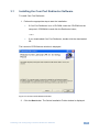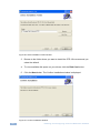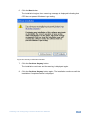
1
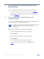
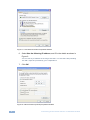
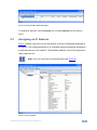
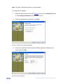
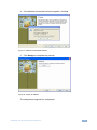
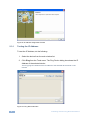
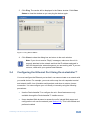
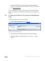
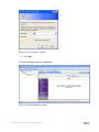
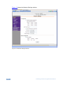
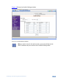
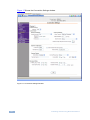
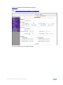
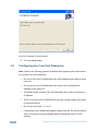
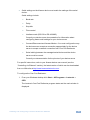
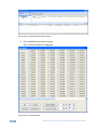
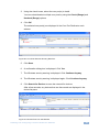
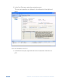
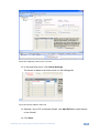
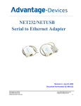
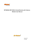
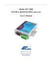
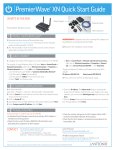
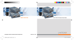
K R A ME R E LE CT R O N IC S L TD . USER GUIDE Ethernet Configuration Guide (Lantronix) P/N: 2900-300321 Rev 6 Contents 1 1.1 1.2 Connecting to the Kramer Device via the Ethernet Port Connecting the Ethernet Port Directly to a PC (Crossover Cable) Connecting via a Straight-through Cable 2 2.1 2.2 2.3 2.4 2.5 3 3.1 3.2 Installing and Running the DeviceInstaller™ Configuration Software Installing DeviceInstaller™ Running DeviceInstaller™ Assigning an IP Address Configuring the Ethernet Port Using DeviceInstaller™ Configuring the Ethernet Port Using the Web Manager Page Installing and Configuring Com Port Redirector Software Installing the Com Port Redirector Software Configuring the Com Port Redirector 1 1 3 4 4 4 5 9 10 16 17 20 Figures Figure 1: Local Area Connection Properties Window Figure 2: Internet Protocol (TCP/IP) Properties Window Figure 3: DeviceInstaller Main Dialog Box Figure 4: Device Details Figure 5: Selecting the Assignment Method Figure 6: Fill in IP Settings Figure 7: Address Unreachable Window Figure 8: Assign IP Address Figure 9: IP Address Assignment Process Figure 10: Ping Device Window Figure 11: Ping Device Status Figure 12: The Web Configuration Tab Figure 13: The Connect to…Window Figure 14: The Web Manager Window Figure 15: Network Settings Window Figure 16: Hostlist Settings Window Figure 17: Connection Settings Window Figure 18: Serial Connection Settings Window Figure 19: Lantronix CPR Welcome Window Figure 20: Select Installation Folder Window Figure 21: Confirm Installation Window Figure 22: Security Confirmation Window Figure 23: Installation Complete Window Figure 24: Com Port Redirector Main Window Figure 25: Com Ports Window Figure 26: Com Ports Window Showing New Port Figure 27: Devices Found on the Network Figure 28: Highlighting a Com Port Figure 29: Assigning a Device to a Com Port Figure 30: Device Added to Com Port 2 2 5 5 6 6 7 7 8 8 9 10 11 11 12 13 14 15 17 18 18 19 20 22 22 23 23 24 25 25 Contents i 1 Connecting to the Kramer Device via the Ethernet Port You can connect the Kramer machine via the Ethernet in the following ways: For direct connection to the PC, use a crossover cable (see Section 1.1) For connection via a network hub or network router, use a straight-through cable (see Section 1.2) 1.1 Connecting the Ethernet Port Directly to a PC (Crossover Cable) You can connect the Ethernet port of the Kramer machine to the Ethernet port on your PC, via a crossover cable with RJ-45 connectors. i This type of connection is recommended for identification of the factory default IP address of the Kramer machine during the initial configuration. After connecting the Ethernet port, configure your PC as follows: 1. Right-click the My Network Places icon on your desktop. 2. Select Properties. 3. Right-click the relevant Local Area Connection Properties. 4. Select Properties. The Local Area Connection Properties window appears. 5. Select the Internet Protocol (TCP/IP) and click Properties (see Figure 1). Connecting to the Kramer Device via the Ethernet Port 1 Figure 1: Local Area Connection Properties Window 6. Select Use the following IP address, and fill in the details as shown in Figure 2. You can use any IP address in the range 192.168.1.1 to 192.168.1.255 (excluding 192.168.1.39) that is provided by your IT department. 7. Click OK. Figure 2: Internet Protocol (TCP/IP) Properties Window 2 Connecting to the Kramer Device via the Ethernet Port 1.2 Connecting via a Straight-through Cable You can connect the Ethernet port of the Kramer machine to the Ethernet port on a network hub or network router, via a straight-through cable with RJ-45 connectors. 1.3 Default Ethernet Communication Parameters IP Address Subnet Mask 255.255.255.0 TCP Port 192.168.1.39 5000 (in some earlier batches TCP Port is set to 10001) Connecting to the Kramer Device via the Ethernet Port 3 2 Installing and Running DeviceInstaller™ To configure your Kramer machine via the Ethernet, install the DeviceInstaller™ configuration software and configure your Ethernet port, and then install the COM Port Redirector to control the Kramer machine. To configure the Ethernet port you must install and run the DeviceInstaller™ configuration software. It is important to consider the following points before logging into and configuring the Ethernet port: The Kramer machine IP address must be configured before a network connection is available (if you encounter problems, see Section 1.1) Only one person at a time may be logged into the network port. This eliminates the possibility of several people simultaneously attempting to configure the device server Network port logins can be disabled. The system manager will not be able to access the unit. This port can also be password protected 2.1 Installing DeviceInstaller™ To install the DeviceInstaller™ Installer, do the following: 1. Insert the product CD into your CD-ROM drive. 2. Run the DeviceInstaller™ installer setup. 3. Respond to the installation wizard prompts. 4. Restart your system. 2.2 Running DeviceInstaller™ Click Start on the Task Bar and select Programs\Lantronix\DeviceInstaller. The DeviceInstaller™ main dialog box is displayed (Figure 3). 4 Installing and Running DeviceInstaller™ Figure 3: DeviceInstaller Main Dialog Box To search for devices, click the Search icon or select Search from the Device menu. 2.3 Assigning an IP Address Figure 4 shows a device found on the network, with the IP addresses assigned at the factory. The hardware address is an individual permanent address assigned to a particular device on the network. The hardware address is found on the product label inside the unit. i Note: Click on a device to view its attributes (see Figure 4). Figure 4: Device Details Installing and Running DeviceInstaller™ 5 Note: The Web Configuration option is recommended. To change the IP address: 1. Select the device from the list (see Figure 4), then click the Assign IP button or select Assign IP Address from the Device menu. 2. Select the assignment method and click Next. Figure 5: Selecting the Assignment Method 3. Fill-in the IP address, Subnet mask and Default gateway to assign to the device and click Next. Figure 6: Fill in IP Settings 6 Installing and Running DeviceInstaller™ 4. If the Address Unreachable window appears, click Yes. Figure 7: Address Unreachable Window 5. Click Assign to complete the process. Figure 8: Assign IP Address The assignment progress bar is displayed. Installing and Running DeviceInstaller™ 7 Figure 9: IP Address Assignment Process 2.3.1 Testing the IP Address To test the IP Address, do the following: 1. Select the device from the main window list. 2. Click Ping from the Tools menu. The Ping Device dialog box shows the IP Address of the selected device. The Ping program verifies that the IP address of the selected device exists on the network Figure 10: Ping Device Window 8 Installing and Running DeviceInstaller™ 3. Click Ping. The results will be displayed in the Status window. Click Clear Status to clear the window so you can ping the device again. Figure 11: Ping Device Status 4. Click Close to close the dialog box and return to the main window. i 2.4 Note: If you do not receive “Reply” messages, make sure the unit is properly attached to the network and that the IP address assigned is valid for the particular network segment you are working with. If you are not sure, check with your systems administrator. Configuring the Ethernet Port Using DeviceInstaller™ You must configure the Ethernet port so that it can communicate on a network with your serial device. For example, you must set the way the unit responds to serial and network traffic, how it handles serial packets, and when to start or close a connection. You can configure your unit locally or remotely using the following procedures: Use the DeviceInstaller™ to configure the unit. Some features are only available through the DeviceInstaller™ Installer menus Use a standard Web browser to access the unit’s internal Web pages and configure the unit over the network (see Section 2.5). This is the easiest and preferred method Installing and Running DeviceInstaller™ 9 Make sure that the Java™ 2 Runtime Environment (Standard Edition, Version 1.4.1 or higher) software is installed on your PC. If not, download it from http://java.sun.com The unit’s configuration is stored in non-volatile memory and is retained without power. The unit performs a reset after the configuration has been changed and stored. 2.5 Configuring the Ethernet Port Using the Web Manager Page To configure the Ethernet Port via a Web browser: 1. Select the Web Configuration tab (see Figure 12). Figure 12: The Web Configuration Tab 2. Select either the internal Web browser (GO) or the External Browser. 3. After clicking GO (for the internal browser), the “Connect to…” window appears. 10 Installing and Running DeviceInstaller™ Figure 13: The Connect to…Window 4. Click OK. The Web Manager window is displayed. Figure 14: The Web Manager Window Installing and Running DeviceInstaller™ 11 Figure 15 shows the Network Settings window. Figure 15: Network Settings Window 12 Installing and Running DeviceInstaller™ Figure 16 Shows the Hostlist Settings window. Figure 16: Hostlist Settings Window i Note: In order to work in the active mode, you must add the remote host IP address and port number to the Hostlist Settings table. Installing and Running DeviceInstaller™ 13 Figure 17 Shows the Connection Settings window. Figure 17: Connection Settings Window 14 Installing and Running DeviceInstaller™ Figure 18 shows the Serial Settings window. Note: Set the port settings to 9600, 8, 1 and None. Figure 18: Serial Connection Settings Window Installing and Running DeviceInstaller™ 15 3 Installing and Configuring Com Port Redirector Software The Com Port Redirector allows any PC running Windows to use ports on a Kramer device as if they were connected directly to the PC. The Redirector creates a virtual COM port within Windows that acts just like the selected serial port on the Kramer device. CPR supports Windows XP, Windows 2000 and 2003 server, and Windows Vista, including Terminal Services. Com Port Redirector consists of the following modules: CPR Manager enables you to map com ports to device servers, configure and test comports CPR Monitor enables you to identify and troubleshoot problems Find detailed instructions for using the modules in the Com Port Redirector online Help. Overall Procedure The following procedure summarizes the steps for using Com Port Redirector: 1. Install Com Port Redirector on each PC that communicates with the device server. 2. Review the general usage guidelines for the device server. 3. Configure the device server and Com Port Redirector. 4. Verify the connectivity between Com Port Redirector and the device server. 16 Installing and Configuring Com Port Redirector Software 3.1 Installing the Com Port Redirector Software To install Com Port Redirector: 1. Perform the appropriate step to start the installation: If Com Port Redirector is on a CD-ROM, insert the CD-ROM into the computer’s CDROM drive and click the Redirector button, —or— If you downloaded Com Port Redirector, double-click the downloaded file. The Lantronix CPR Welcome window is displayed. Figure 19: Lantronix CPR Welcome Window 2. Click the Next button. The Select Installation Folder window is displayed. Installing and Configuring Com Port Redirector Software 17 Figure 20: Select Installation Folder Window 3. Browse to the folder where you want to install the CPR. We recommend you select the default. 4. To view available disk space on your drives, click the Disk Cost button. 5. Click the Next button. The Confirm Installation window is displayed. Figure 21: Confirm Installation Window 18 Installing and Configuring Com Port Redirector Software 6. Click the Next button. The installation begins; then a warning message is displayed indicating that CPR has not passed Windows Logo testing. Figure 22: Security Confirmation Window 7. Click the Continue Anyway button. The installation continues and the warning is displayed again. 8. Click the Continue Anyway button again. The installation continues until the Installation Complete window is displayed. Installing and Configuring Com Port Redirector Software 19 Figure 23: Installation Complete Window 9. Click the Close button. 3.2 Configuring the Com Port Redirector Note: Observe the following general guidelines when preparing the device server for use with Com Port Redirector: Do not run the Com Port Redirector with other software that installs a virtual com port Do not run the Com Port Redirector with other Com Port Redirection software on the same PC The device server to which Com Port Redirector will connect must have an IP address The PC running Com Port Redirector must have a good network connection to the device server Do not use com ports 1, 2, 3 or 4 If redirecting over a Wide Area Network (WAN), both the PC and the device server must have a correct gateway address configured in their TCP/IP settings 20 Installing and Configuring Com Port Redirector Software Serial settings on the Kramer device must match the settings of the serial device. Serial settings include: Baud rate Parity Stop bits Flow control Interface mode (RS-232 or RS-422/485) Consult your device server documentation for information about configuring these serial settings for your device server Connect/Disconnect and Access Modes—You must configure the way the device server accepts a connection appropriately for the device server to accept a network connection from Com Port Redirector Serial cabling between the managed serial device and the device server must be correct. Consult your documentation for the pinouts of your device server For specific instructions, refer to your Kramer device user manual (see the “Controlling via Ethernet” section), the latest version of which can be downloaded from our Web site at http://www.kramerelectronics.com. To configure the Com Port Redirector: 1. From your Windows desktop click Start > All Programs > Lantronix > CPR. The Lantronix Com Port Redirector program starts and the main window is displayed. Installing and Configuring Com Port Redirector Software 21 Figure 24: Com Port Redirector Main Window 2. Click Add/Remove to add com ports. The Com Ports window is displayed. Figure 25: Com Ports Window 22 Installing and Configuring Com Port Redirector Software 3. Using the check boxes, select the com port(s) to install. You can select/deselect multiple com ports by using the Check (Range) and Uncheck (Range) options. 4. Click OK. The selected com port(s) are displayed in the Com Port Redirector main window. Figure 26: Com Ports Window Showing New Port 5. Click Save. 6. A confirmation dialog box is displayed. Click Yes. 7. The Windows security warning is displayed. Click Continue Anyway. 8. The Windows security warning is displayed again. Click Continue Anyway. 9. Click Search for Devices to scan the network for devices. After a few seconds, any devices that are discovered are displayed in the device list pane. Figure 27: Devices Found on the Network Installing and Configuring Com Port Redirector Software 23 10. In the Com Ports pane, select the required com port. The com port properties are displayed in the settings tab in the right hand pane. Figure 28: Highlighting a Com Port 11. In the Device List pane, right-click the device to associate it with the com port. 24 Installing and Configuring Com Port Redirector Software Figure 29: Assigning a Device to a Com Port 12. In the drop-down menu, click Add to Settings. The device is added in the Host column on the Settings tab. Figure 30: Device Added to Com Port 13. Optional—If your PC is behind a firewall, click Add Rx Port to open the port on the firewall. 14. Click Save. Installing and Configuring Com Port Redirector Software 25