1
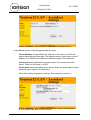
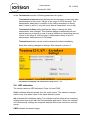
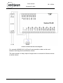
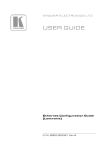
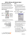
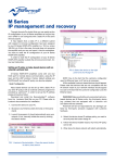
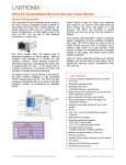
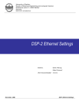
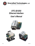
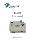
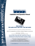
User manual 20.11.2014 Neutron12-LAN NEUTRON12-LAN 1 General Neutron12-LAN is a general purpose pulse counter designed for collecting and reporting pulses from different kind of energy and consumption meters. Pulses are collected on an hourly basis and sent to server once per day. 2 Introduction 2.1 Connect and power up 1. Connect power supply, measuring device (or devices) and LAN network cable to the device. 2. The red PWR led indicates when the device has power. Picture 1: Device front panel. 2.2 Configuring the device Lantronix DeviceInstaller application is used to configure the device. The application should be installed and run on a computer that is either connected to the same local area network with the device, or directly connected to the device. The application may be downloaded from: http://www.lantronix.com/support/downloads/?p=XPORT If the local area network uses a DHCP server, Neutron12-LAN, when powered up with default settings, will obtain an IP address to the local area network. The device may also use a static IP address 1. Start Lantronix DeviceInstaller on your computer. 2. The device appears in the device list on the left, see Picture 2. The picture shows the firmware version v6.9.0.2 and device IP address 192.168.100.29. If the device does not appear, click the Search button. Copyright 2014 - ionSign www.ionsign.fi v1.4 User manual 20.11.2014 Neutron12-LAN 3. Select the device by clicking its IP address. Select Web Configuration tab on the right side window. 4. In the address field, input 10001 as the port of the device IP address. Click on the white arrow on green background. Settings menu appears below the address, see picture 2. (The Settings interface is currently only in Finnish, refer to translations in the following pictures.) Picture 2: Lantronix DeviceInstaller application. 2.3 Device settings The settings menu has three sections: Device, Server and Transmission. In the Device section, following parameters are given: Device ID setting defines a unique identifier for each device. Values in the range 1-65535. Value 0 indicates that the device is not operational. Number of inputs setting defines the number of connected meters for reading and transmitting pulse data. Values in the range 1-12. Save after making changes to settings. See example in picture 3. Copyright 2014 - ionSign www.ionsign.fi v1.4 User manual 20.11.2014 Neutron12-LAN Picture 3: EXAMPLE – Device ID set to 16 and number of inputs set to 12. In the Server section, following parameters are given: Server address setting defines the address of the server, to which the device transmits the pulse data. The address may be input either as an IP address or in DNS format. Maximum address length is 30 characters. Server port setting defines the number of port to be connected at the server. Values in the range 1-65535. Server path defines the folder at the server where the pulse data is stored. Maximum path length is 50 characters. Save after making changes to settings. See example in picture 4. Picture 4: EXAMPLE – Server address set to services.ionsign.fi, server port set to 80 and server path set to /neutrontest/input2/ Copyright 2014 - ionSign www.ionsign.fi v1.4 User manual 20.11.2014 Neutron12-LAN In the Transmission section, following parameters are given: Transmission interval setting defines the time between consecutive data transmissions to the server. Values in the range 0-65535 seconds. This transmission takes place in addition to the daily transmission of hourly data. If value is set to 0, only the hourly data is transmitted, once a day. Transmission delay setting defines the delay in starting the daily transmission after midnight. This enables staggered transmissions and avoids jamming of server in case of a large number of transmitting devices. Values in the range 0-1000 minutes. If transmission delay is set to 0, transmission takes place at 12 PM sharp. Transmit now button can be used to transmit the data immediately. Save after making changes to settings. See example in picture 5. Picture 5: EXAMPLE – Transmission interval set to 0 s (only hourly data is transmitted at midnight) and transmission delay set to 1 min. 2.4 LED indicators The device has three LED indicators: Pulse, Init and PWR. Pulse indicates detected pulses from the meter inputs. The indicator changes status every time when some of the inputs detects a pulse. Init indicates the installation status. The indicator starts to blink when necessary settings have been input with the DeviceInstaller application. When the indicator is lit continuously, settings are complete and the device has connection with the server. PWR indicates the power supply. Copyright 2014 - ionSign www.ionsign.fi v1.4 User manual 20.11.2014 Neutron12-LAN 3 Neutron12-LAN specifications Inputs: 12 pulse inputs for open collector or relay outputs of meters. Open collector or relay output sourcing voltage 12 VDC, maximum sourcing current 5mA. Operating voltage: 11…13 VDC. Current consumption: 70 mA. Real-time clock: 4 days backup. Size: WxHxD 105 x 90 x 52 mm (6 module wide DIN rail enclosure). Protection class: IP20. Operating temperature: -25°C...+55°C. RH: 5% - 95% non-condensing. Data storage capacity: 30 days for each hour for and input channel. Data transfer capability: LAN / TCP-IP 4 Warranty ionSign Oy agrees the warranty of two (2) years for Neutron devices. Warranty starts from the day when the customer has received the device and it concerns material and production defects. Warranty is not agreed for devices which are used or wired incorrectly. It is not also agreed for situations where defect is related to 3rd party actions. Things like this can be service changes by mobile network operator or changes in mobile network itself. For devices which are broken during warranty time ionSign Oy delivers a new device for free. Alternatively device can be corrected. Broken device should be returned to supplier if required. The cost of delivery is paid by supplier. ionSign Oy is not responsible for indirect or implicit damage or possible work or travel expenses related to broken device. For warranty issues please contact to ionSign Oy by e-mail: [email protected] or by tel: +358 (0)2 822 0097. Copyright 2014 - ionSign www.ionsign.fi v1.4 User manual 20.11.2014 Neutron12-LAN Picture 6: Neutron12-LAN circuit diagram. For example JAMAK 2x(2+1)x0,5mm2 instrumentation cable can be used between metering device and Neutron device. The open collector or relay output of single meter is connected to Neutron device as shown above. Copyright 2014 - ionSign www.ionsign.fi v1.4