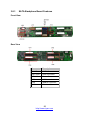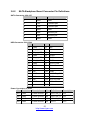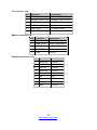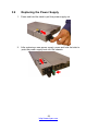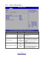
1
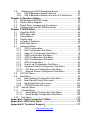
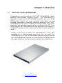
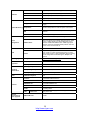
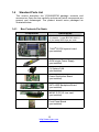
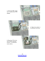
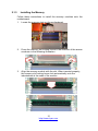
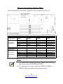
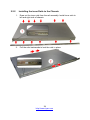
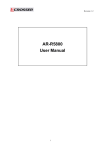
YR188-B537M Service Engineer’s Manual 1 http://www.tyan.com 2 http://www.tyan.com PREFACE Copyright This publication, including all photographs, illustrations, and software, is protected under international copyright laws, with all rights reserved. Neither this manual, nor any material contained herein, may be reproduced without written consent of manufacturer. Copyright 2009 MiTAC International Corporation. All rights reserved. ® TYAN is a registered trademark of MiTAC International Corporation. Version 1.00 Disclaimer Information contained in this document is furnished by MiTAC International Corporation and has been reviewed for accuracy and reliability prior to printing. MiTAC assumes no liability whatsoever, and disclaims any ® express or implied warranty, relating to sale and/or use of TYAN products including liability or warranties relating to fitness for a particular purpose or merchantability. MiTAC retains the right to make changes to produce descriptions and/or specifications at any time, without notice. In no event will MiTAC be held liable for any direct or indirect, incidental or consequential damage, loss of use, loss of data or other malady resulting from errors or inaccuracies of information contained in this document. Trademark Recognition All registered and unregistered trademarks and company names contained in this manual are property of their respective owners including, but not limited to the following. TYAN® is a trademark of MiTAC International Corporation. ® ® Intel is a trademark of Intel Corporation. ® ® AMI , AMIBIOS and combinations thereof are trademarks of AMI Technologies. Microsoft®, Windows® are trademarks of Microsoft Corporation. ® ® ® ® IBM , PC , AT and PS/2 are trademarks of IBM Corporation. Winbond® is a trademark of Winbond Electronics Corporation. 3 http://www.tyan.com Federal Communication Commission (FCC) Notice for the USA Compliance Information Statement (Declaration of Conformity Procedure) DoC FCC Part 15: This device complies with part 15 of the FCC Rules Operation is subject to the following conditions: 1) This device may not cause harmful interference; 2) This device must accept any interference received including interference that may cause undesired operation. If this equipment does cause harmful interference to radio or television reception, which can be determined by turning the equipment off and on, the user is encouraged to try one or more of the following measures: – Reorient or relocate the receiving antenna. – Increase the separation between the equipment and the receiver. – Plug the equipment into an outlet on a circuit different from that of the receiver. Consult the dealer on an experienced radio/television technician for help. Notice for Canada This apparatus complies with the Class A limits for radio interference as specified in the Canadian Department of Communications Radio Interference Regulations. (Cet appareil est conforme aux norms de Classe A d’interference radio tel que specifie par le Ministere Canadien des Communications dans les reglements d’ineteference radio.) Notice for Europe (CE Mark) This product is in conformity with the Council Directive 89/336/EEC, 92/31/EEC (EMC). CAUTION: Lithium battery included with this board. Do not puncture, mutilate, or dispose of battery in fire. There will be danger of explosion if battery is incorrectly replaced. Replace only with the same or equivalent type recommended by manufacturer. Dispose of used battery according to manufacturer instructions and in accordance with your local regulations. 4 http://www.tyan.com About this Manual This manual provides you with instructions on installing your TYAN YR188-B537M. This Manual is intended for experienced users and integrators with hardware knowledge of personal computers. This manual consists of the following parts: Chapter1: Provides an introduction to the TYAN YR188-B537M barebones, standard parts list, describes the external components, gives a table of key components, and provides block diagram of the system. Chapter2: Covers procedures on installing the CPU, memory modules and hard drives. Chapter3: Covers removal and replacement procedures for pre-installed components. Chapter4: Covers the block diagram, MB layout and pin definitions for headers and jumpers. Chapter5: Covers various BIOS settings that can be used to Appendix: List the cable connection and FRU part tables for reference of system setup, and technical support in case a problem arises with your system. configure your system. 5 http://www.tyan.com SAFETY INFORMATION Before installing and using TYAN YR188-B537M, take note of the following precautions: ·Read all instructions carefully. ·Do not place the unit on an unstable surface, cart, or stand. ·Do not block the slots and opening on the unit, which are provided for ventilation. ·Only use the power source indicated on the marking label. If you are not sure, contact the power company. ·The unit uses a three-wire ground cable, which is equipped with a third pin to ground the unit and prevent electric shock. Do not defeat the purpose of this pin. If you outlet does not support this kind of plug, contact your electrician to replace your obsolete outlet. ·Do not place anything on the power cord. Place the power cord where it will not be in the way of foot traffic. ·Follow all warnings and cautions in this manual and on the unit case. ·Do not push objects in the ventilation slots as they may touch high voltage components and result in shock and damage to the components. ·When replacing parts, ensure that you use parts specified by the manufacturer. ·When service or repairs have been done, perform routine safety checks to verify that the system is operating correctly. ·Avoid using the system near water, in direct sunlight, or near a heating device. ·Cover the unit when not in use. 6 http://www.tyan.com Table of Contents Chapter 1: Overview ......................................................................... 9 1.1 About the TYAN YR188-B537M ............................................... 9 1.2 Product Models....................................................................... 10 1.3 Features.................................................................................. 11 1.4 Standard Parts List ................................................................. 15 1.4.1 Box Contents Per Node ................................................... 15 1.4.2 Accessories ..................................................................... 16 1.5 About the Product ................................................................... 18 1.5.1 System Front View (Per Node)........................................ 18 1.5.2 System Rear View (Per Node) ........................................ 20 1.5.3 Internal View (Per Node) ................................................. 21 Chapter 2: Setting Up..................................................................... 23 2.0.1 Before you Begin ............................................................. 23 2.0.2 Work Area........................................................................ 23 2.0.3 Tools ................................................................................ 23 2.0.4 Precautions...................................................................... 24 2.1 Installing Motherboard Components....................................... 25 2.1.1 Installing Hard Drives....................................................... 25 2.1.2 Installing the CPU and Heatsink...................................... 28 2.1.3 Installing the Memory....................................................... 31 2.2 Rack Mounting........................................................................ 33 2.2.1 Installing the Server in a Rack......................................... 33 2.2.2 Installing the inner Rails to the Chassis........................... 34 2.2.3 Installing the Outer Rails to the Rack .............................. 35 2.2.4 Rack mounting the Server ............................................... 36 Chapter 3: Replacing Pre-Installed Components ........................ 37 3.1 Introduction ............................................................................. 37 3.2 Disassembly Flowchart........................................................... 37 3.3 Removing the Cover ............................................................... 39 3.4 Replacing Motherboard Components..................................... 39 3.4.1 Replacing Expansion Card .............................................. 39 3.4.2 Disconnecting All Motherboard Cables ........................... 41 3.4.3 Removing the Motherboard ............................................. 42 3.5 Replacing the Power Distribution Board ............................... 43 3.6 Replacing the Front Panel Board.......................................... 44 3.6.1 Front Panel Board Features ............................................ 46 3.6.2 Front Panel Board Connector Pin Definition ................... 46 3.7 Replacing the System Fan.................................................... 47 7 http://www.tyan.com 3.8 Replacing the SATA Backplane Board ................................. 49 3.8.1 SATA Backplane Board Features.................................... 50 3.8.2 SATA Backplane Board Connector Pin Definitions ......... 51 Chapter 4: Hardware Setup............................................................ 55 4.1 Motherboard (S537M) Image ................................................. 55 4.2 System Block Diagram ........................................................... 56 4.3 Board Parts, Jumpers and Connectors .................................. 57 4.4 Installing Optional SO-DIMM modules ................................... 63 Chapter 5: BIOS Setup ................................................................... 65 5.1 About the BIOS....................................................................... 65 5.2 BIOS Menu Bar....................................................................... 65 5.3 Setup Basics........................................................................... 66 5.4 Getting Help............................................................................ 66 5.5 In Case of Problems ............................................................... 66 5.6 BIOS Main Menu .................................................................... 67 5.7 Advanced Menu...................................................................... 68 5.7.1 CPU Configuration........................................................... 70 5.7.2 IDE Configuration Sub-Menu........................................... 72 5.7.3 Super IO Configuration Sub-Menu .................................. 76 5.7.4 USB Configuration Sub-Menu ......................................... 77 5.7.5 ACPI Configuration Sub-Menu ........................................ 80 5.7.6 AHCI Configuration Sub-Menu ........................................ 83 5.7.7 APM Configuration........................................................... 85 5.7.8 Event Log Configuration Sub-Menu ................................ 87 5.7.9 Hardware Health Configuration Sub-Menu ..................... 88 5.7.10 PCI Express Configuration Sub-Menu........................... 92 5.7.11 Remote Access Configuration Sub-Menu ..................... 93 5.8 PCI PnP Menu ........................................................................ 95 5.9 Boot Menu .............................................................................. 97 5.9.1 Boot Settings Configuration Sub-Menu ........................... 98 5.9.2 Boot Device Priority Sub-menu ..................................... 100 5.9.3 Hard Disk Drives Sub-menu .......................................... 101 5.9.4 CD/DVD Drives Sub-menu ............................................ 102 5.10 Security Menu..................................................................... 103 5.11 Chipset Menu...................................................................... 105 5.11.1 North Bridge Configuration Sub-Menu ........................ 106 5.11.2 South Bridge Configuration Sub-Menu........................ 108 5.12 Exit Menu............................................................................ 110 Appendix I: Cable Connection Tables ........................................ 113 Appendix II: FRU Parts Table ...................................................... 115 Appendix III: Technical Support.................................................. 117 8 http://www.tyan.com Chapter 1: Overview 1.1 About the TYAN YR188-B537M ® Congratulations on your purchase of the TYAN YR188-B537M, a highly optimized rack-mountable barebone system. The YR188-B537M is ® designed to support one Intel 5200/5400 processor and up to 32GB DDR2-667/533 memory per node, providing a rich feature set and ® incredible performance. Leveraging advanced technology from Intel , YR188-B537M server system is capable of offering scalable 32 and 64-bit computing, high bandwidth memory design, and lightning-fast PCI-E bus implementation. The YR188-B537M not only empowers your company in nowadays IT demand but also offers a smooth path for future application usage. ® TYAN is also proud to deliver the YR188-B537M in flavor while supporting up to eight hot-swap hard drives (four per node). The ® YR188-B537M uses TYAN ’s latest chassis featuring a robust structure and a solid mechanical enclosure. All of this provides YR188-B537M the power and flexibility to meet the needs of nowadays server application. 9 http://www.tyan.com 1.2 Product Models Model B537MY188S1 (one node) B537MY188S2 (two nodes) HDD Bays Power supply Hot-swap, 4 HDDs (1) 450W Hot-swap, 8 HDDs (2) 450W 10 http://www.tyan.com 1.3 Features TYAN YR188-B537M System Front Panel External Drive Bay System Cooling Configuration Power Supply Processor Chipset Memory Expansion Slots LAN (B537MY188S2) Form Factor 1U Rackmount Chassis Name YR188 Dimension (H x W x D) 1.71" x 17.26" x 28.74" (43.5 x 438.5 x 730mm) Node Carrier Dimension 1.61" x 8.35" x 28.74" (40.8 x 212 x 730mm) Feature Two nodes in one chassis Buttons (1) RST / (1) ID / (1) PWR LEDs (1) Power / (1) BMC / (2) LAN / (1) HDD I/O Ports (2) USB ports Type / Q'ty 2.5" Hot-Swap / (4) per node, total (8) Supported HDD Interface SATA-II 3.0Gb/s FAN (3) 4cm fans per node, total (6) Output Watts (1) 450 Watts per node, total (2) Efficiency PFC Supported CPU Series Intel® Xeon® processor 5400/5200 series Socket Type / Q'ty LGA771 Thermal Design Power (TDP) wattage 80W System Bus FSB 1333/1066MHz MCH / ICH Intel 5100 / ICH9R Super I/O Winbond W83627DHG Supported DIMM Qty (8) DIMM sockets per node, total (16) DIMM Type / Speed DDR2 667/533 RDIMM Capacity Up to 32GB RDIMM per node, total 64GB Memory channel 2 Channels PCI-E (1) PCI-E Low-Profile x16 slot per node, total (2) Pre-installed TYAN Riser Card M2087-R, PCI-E x16 1U riser card (right) Port Q'ty (2) per node, total (4) Controller Intel 82571EB Controller Storage Graphic SATA Chipset ICH9R Speed 3.0 Gb/s RAID RAID 0/1/10/5 (Intel® Matrix RAID) XGI Volari™ Z9s 11 http://www.tyan.com I/O Ports USB (4) ports (2 at front, 2 at rear) per node, total (8) COM (1) DB-9 port per node, total (2) VGA (1) D-sub port per node, total (2) RJ-45 (3) ports per node, total (6) Chipset Winbond W83793G Voltage Monitors voltage for CPU, memory, chipset & power supply System Monitoring Temperature Server Management BIOS Operating System Regulation Operating Environment RoHS Contains LED Fan fail LED indicator / Over temperature warning indicator Others Watchdog timer support Optional SMDC M3296 IPMI 2.0 remote system management card M3296 Feature KIRA 100 (Single Chip KVM/IP+IPMI processor) / KVM over IP / Video output over LAN (1280x1024) / Card interface: DDR2 SO-DIMM socket / USB2 high speed interface / Remote CD-ROM (media) redirect / Remote power on/off, reset and soft off Brand / ROM size AMI / 1MB Feature Plug and Play (PnP) /PCI2.3 /WfM2.0 /SMBIOS2.3 /PXE boot / ACPI 2.0 power management /Power on mode after power recovery / User-configurable H/W monitoring / Auto-configurable of hard disk types / Multiple boot options OS supported list Please refer to our OS supported list. FCC (DoC) Class A CE (DoC) Yes Operating Temp. 10° C ~ 35° C (50° F~ 95° F) Non-operating Temp. - 40° C ~ 70° C (-40° F ~ 158° F) In/Non-operating Humidity 90%, non-condensing at 35° C RoHS 6/6 Complaint Yes Barebone (1) B537MY188S2 Barebone Manual (1) MB Quick Reference + (1) BB User's manual Installation CD (1) TYAN installation CD Heatsink / Cooler (2) LGA771 CPU heatsinks Rail kit (1) sliding rail kit Cable Optional accessories for future upgrade Monitors temperature for CPU & system environment Power Cord SMDC IPMI Card (2) CCBL-0310, US type power cord / (2) CCBL-0300, EU type power cord M3296 12 http://www.tyan.com TYAN YR188-B537M System Front Panel External Drive Bay System Cooling Configuration Power Supply Processor Chipset Memory Expansion Slots LAN Storage (B537MY188S1) Form Factor 1U Rackmount Chassis Name YR188 Dimension (H x W x D) 1.71" x 17.26" x 28.74" (43.5 x 438.5 x 730mm) Node Carrier Dimension 1.61" x 8.35" x 28.74" (40.8 x 212 x 730mm) Feature One nodes in one chassis Buttons (1) RST / (1) ID / (1) PWR LEDs (1) Power / (1) BMC / (2) LAN / (1) HDD I/O Ports (2) USB ports Type / Q'ty 2.5" Hot-Swap / (4) per node Supported HDD Interface SATA-II 3.0Gb/s FAN (3) 4cm fans per node Output Watts (1) 450 Watts per node Efficiency PFC Supported CPU Series Intel® Xeon® processor 5400/5200 series Socket Type / Q'ty LGA771 Thermal Design Power (TDP) wattage 80W System Bus FSB 1333/1066MHz MCH / ICH Intel 5100 / ICH9R Super I/O Winbond W83627DHG Supported DIMM Qty (8) DIMM sockets per node DIMM Type / Speed DDR2 667/533 RDIMM Capacity Up to 32GB RDIMM per node Memory channel 2 Channels PCI-E (1) PCI-E Low-Profile x16 slot per node Pre-installed TYAN Riser Card M2087-R, PCI-E x16 1U riser card (right) Port Q'ty (2) per node Controller Intel 82571EB SATA Controller ICH9R Speed 3.0 Gb/s RAID RAID 0/1/10/5 (Intel® Matrix RAID) Graphic Chipset I/O Ports USB (4) ports (2 at front, 2 at rear) per node COM (1) DB-9 port per node XGI Volari™ Z9s 13 http://www.tyan.com VGA (1) D-sub port per node RJ-45 (3) ports per node Chipset Winbond W83793G Voltage Monitors voltage for CPU, memory, chipset & power supply System Monitoring Temperature Server Management BIOS Operating System Regulation Operating Environment RoHS Contains LED Fan fail LED indicator / Over temperature warning indicator Others Watchdog timer support Optional SMDC M3296 IPMI 2.0 remote system management card M3296 Feature KIRA 100 (Single Chip KVM/IP+IPMI processor) / KVM over IP / Video output over LAN (1280x1024) / Card interface: DDR2 SO-DIMM socket / USB2 high speed interface / Remote CD-ROM (media) redirect / Remote power on/off, reset and soft off Brand / ROM size AMI / 1MB Feature Plug and Play (PnP) /PCI2.3 /WfM2.0 /SMBIOS2.3 /PXE boot / ACPI 2.0 power management /Power on mode after power recovery / User-configurable H/W monitoring / Auto-configurable of hard disk types / Multiple boot options OS supported list Please refer to our OS supported list. FCC (DoC) Class A CE (DoC) Yes Operating Temp. 10° C ~ 35° C (50° F~ 95° F) Non-operating Temp. - 40° C ~ 70° C (-40° F ~ 158° F) In/Non-operating Humidity 90%, non-condensing at 35° C RoHS 6/6 Complaint Yes Barebone (1) B537MY188S1 Barebone Manual (1) MB Quick Reference + (1) BB User's manual Installation CD (1) TYAN installation CD Heatsink / Cooler (1) LGA771 CPU heatsink Rail kit (1) sliding rail kit Cable Optional accessories for future upgrade Monitors temperature for CPU & system environment Power Cord SMDC IPMI Card (2) CCBL-0310, US type power cord / (2) CCBL-0300, EU type power cord M3296 14 http://www.tyan.com 1.4 Standard Parts List This section describes the YR188-B537M package contents and accessories. Open the box carefully and ensure that all components are present and undamaged. The product should arrive packaged as illustrated below. 1.4.1 Box Contents Per Node Component Description 1U chassis, 2 nodes (B537MY188S2) 1U chassis, 1 node (B537MY188S1) (4) hot swap HDD bays per node ® TYAN S537M system board (pre-installed) 450W single Power Supply (pre-installed) (3) System FAN (pre-installed) Power Distribution Board (pre-installed) SATA HDD Backplane Board (pre-installed) M2087-R PCI-E riser card (pre-installed) Front Panel Board (pre-installed) 15 http://www.tyan.com 1.4.2 Accessories If any items are missing or appear damaged, contact your retailer or ® browse to TYAN ’s website for service: http://www.tyan.com The web site also provides information of other TYAN® products, as well as FAQs, compatibility lists, BIOS settings, etc. ® 1 x TYAN Motherboard Drive CD 1 Heatsink (B537MY188S1) 2 Heatsinks (B537MY188S2) HDD Screws Power Cables (Left to right: Europe, US) 1 Europe + 1 US (B537MY188S1) 2 Europe + 2 US (B537MY188S2) Barebone Manual Mainboard Quick Reference 16 http://www.tyan.com Rail Kit Rail x 2 Screw Pack 17 http://www.tyan.com 1.5 About the Product The following views show you the product. 1.5.1 System Front View (Per Node) HDD LED Activity LED: Off Description Drive present, no activity Fault LED: Off Activity LED: blinking green Fault LED: Off Activity LED: Off Drive present, with activity HDD Fail Fault LED: Red Activity LED: random Fault LED: blinking red @ 4 Hz Activity LED: random Fault LED: blinking red @ 1 Hz Identify Rebuild 18 http://www.tyan.com Front Panel LED Power Description Green: Power On Green: Normal Status Amber: System Failed IPMI Without IPMI module: FAN failed system thermal problem With IPMI module: IPMI fault alert event is raised. LAN1 LAN2 Green: Link Blinking Green: Activity Green: Link Blinking Green: Activity Green: Ready HDD Blinking Green: Activity Red: TBD Front Panel Button Description Power On/ Off Power up and power down the system (Use a pin) ID (UID) Press once and the blue ID LED on the rear panel will light up Reset Press to reset the system 19 http://www.tyan.com 1.5.2 System Rear View (Per Node) ÆID LED: When the ID button on the front panel is pressed, the blue ID LED on the rear panel will light up. The technical personnel can easily locate the system on the rack, disconnect cables from the system, and remove it from the rack for later repair. ÆLAN LED: The three onboard Ethernet ports have green and amber LEDs to indicate LAN status. The table below illustrates the different LED states. Ethernet LAN Link/Activity LED Left: slow blinking green Right: Off Left: blinking green 10 Mbps Link 10 Mbps Activity Right: Off Left: slow blinking green Right: green Left: blinking green 100 Mbps Link 100 Mbps Activity Right: green Left: slow blinking green Right: amber Description 1000 Mbps Link 20 http://www.tyan.com Left: blinking green 1000 Mbps Activity Right: amber Left: Off No Link Right: Off 1.5.3 Internal View (Per Node) Number Description 1 HDD Cage 2 SATA HDD Backplane Board 3 Power Distribution Board 4 System Fans 5 Power Supply 6 PCI-E Riser Card Assembly 21 http://www.tyan.com NOTE 22 http://www.tyan.com Chapter 2: Setting Up 2.0.1 Before you Begin This chapter explains how to install the CPUs, CPU heatsinks, memory modules, and hard drives. Instructions on inserting add on cards are also given. 2.0.2 Work Area Make sure you have a stable, clean working environment. Dust and dirt can get into components and cause malfunctions. Use containers to keep small components separated. Putting all small components in separate containers prevents them from becoming lost. Adequate lighting and proper tools can prevent you from accidentally damaging the internal components. 2.0.3 Tools The following procedures require only a few tools, including the following: z A cross head (Phillips) screwdriver z A grounding strap or an anti-static pad Most of the electrical and mechanical connections can be disconnected with your hands. It is recommended that you do not use pliers to remove connectors as it may damage the soft metal or plastic parts of the connectors. 23 http://www.tyan.com 2.0.4 Precautions Components and electronic circuit boards can be damaged by discharges of static electricity. Working on a system that is connected to a power supply can be extremely dangerous. Follow the guidelines below to avoid damage to YR188-B537M or injury to yourself. z Ground yourself properly before removing the top cover of the system. Unplug the power from the power supply and then touch a safely grounded object to release static charge (i.e. power supply case). If available, wear a grounded wrist strap. Alternatively, discharge any static electricity by touching the bare metal chassis of the unit case, or the bare metal body of any other grounded appliance. z Avoid touching motherboard components, IC chips, connectors, memory modules, and leads. z The motherboard is pre-installed in the system. When removing the motherboard, always place it on a grounded anti-static surface until you are ready to reinstall it. z Hold electronic circuit boards by the edges only. Do not touch the components on the board unless it is necessary to do so. Do not flex or stress circuit boards. z Leave all components inside the static-proof packaging that they ship with until they are ready for installation. z After replacing optional devices, make sure all screws, springs, or other small parts are in place and are not left loose inside the case. Metallic parts or metal flakes can cause electrical shorts. Note: All connectors are keyed to only attach one way. All use the correct screw size as indicated in the procedures. 24 http://www.tyan.com 2.1 Installing Motherboard Components This section describes how to install components on to the mainboard, including CPUs, memory modules, HDD and add on cards. 2.1.1 Installing Hard Drives The YR188-B537M supports four 2.5” hard drives per node. Follow these instructions to install a hard drive. 1. Press the locking tabs at both sides to pull the node out. 2. First remove the power supply (see 3.9 Replacing the Power Supply for details). Unscrew to lift up the node cover. 3. Press the locking lever latch and pull the locking lever open. 25 http://www.tyan.com 4. Slide the HDD tray out. 5. Unscrew the HDD tray bracket. 6. Place a hard drive into the drive tray. Use four screws to secure the HDD. 7. Reinsert the HDD tray into the chassis. 26 http://www.tyan.com 8. Press the locking lever to secure the tray. Repeat the same procedures to install other HDD trays. 27 http://www.tyan.com 2.1.2 Installing the CPU and Heatsink Follow the steps below to install the processor and heatsink. 1. Locate the CPU socket. 2. Take off the CPU protection cap. 28 http://www.tyan.com 3. Pull the CPU lever up to unlock the CPU socket 4. Open the socket in the direction as shown. 5. Place the CPU in the CPU socket, ensuring that pin 1 is located as shown below. 29 http://www.tyan.com 6. Close the socket and press the CPU socket lever down to secure the CPU. 7. Place the heatsink on top of the CPU and secure it with 4 screws. 30 http://www.tyan.com 2.1.3 Installing the Memory Follow these instructions to install the memory modules onto the motherboard. 1. Locate the memory slots on the motherboard. 2. Press the memory slot locking levers in the direction of the arrows as shown in the following illustration. 3. Align the memory module with the slot. When inserted properly, the memory slot locking levers lock automatically onto the indentations at the ends of the module. 31 http://www.tyan.com Memory Population Option Table The following table outlines the suggested rules for populating memory. Memory Population Rules DIMM Configuration DIMM7 DIMM5 DIMM3 DIMM1 Four DIMMs per Channel 1 Empty Empty Empty Single Rank Empty Empty Empty Empty Single Rank Single Rank Empty Empty Empty Single Rank Single Rank Single Rank Empty Dual Rank Single Rank Single Rank Single Rank Single Rank Dual Rank Dual Rank DIMM Configuration DIMM6 DIMM4 DIMM2 DIMM0 Four DIMMs per Channel 0 Empty Empty Empty Single Rank Empty Empty Empty Empty Single Rank Single Rank Empty Empty Empty Single Rank Single Rank Single Rank Empty Dual Rank Single Rank Single Rank Single Rank Single Rank Dual Rank Dual Rank Note: 1). For optimal dual channel operations, always install memory in pairs beginning with DIMM0 and DIMM1. 2). For single channel mode, install one DIMM at DIMM0 or DIMM1. Others must be in dual channel mode. 32 http://www.tyan.com 2.2 Rack Mounting After installing the necessary components, the TYAN YR188-B537M can be mounted in a rack using the supplied rack mounting kit. Rack mounting kit No. 2.2.1 Description Quantity A Item Sliding rails 2 B Screw kit 1 Installing the Server in a Rack Follow these instructions to mount the TYAN YR188-B537M into an industry standard 19” rack. NOTE: Before mounting the TYAN YR188-B537M in a rack, ensure that all internal components have been installed and that the unit has been fully tested. Screw Kit List No. Size Quantity A Screw M5 8 B Washer 8 Total: A+B M5 and Washer Total: 8 sets 33 http://www.tyan.com 2.2.2 Installing the inner Rails to the Chassis 1. Draw out the inner rails from the rail assembly. Install inner rails to left and right side of chassis. 2. Pull the rails backwards to lock the rails in place. 34 http://www.tyan.com 2.2.3 Installing the Outer Rails to the Rack 1. Measure the distance between inner side of the front and rear mounting brackets in the rack. 2. Secure the outer rail to the rack using 4 M5 screws and 4 washers (2 sets front / 2 sets rear) for each side. Secure the rails to the rack as shown. 35 http://www.tyan.com 2.2.4 Rack mounting the Server 3. Draw out the middle rail to the latch position. 4. Lift the chassis and then insert the inner slide rails into the middle rails. 5. Press the front latch keys on both sides of the chassis to push the system into the rack. To pull the whole system out, press the rear latch keys on both sides of the chassis. Note: To avoid injury, it is strongly recommended that two people lift the TYAN YR188-B537M into the place while a third person screws it to the rack. 36 http://www.tyan.com Chapter 3: Replacing Pre-Installed Components 3.1 Introduction This chapter explains how to replace the pre-installed components, including the Motherboard, front panel board, SATA HDD board, M2087-R PCI-E Riser card, System fans, and Power supply unit etc. 3.2 Disassembly Flowchart The following flowchart outlines the disassembly procedure. Rear Components Node Cover DIMMs Power Mainboard CPU/Heatsink Assembly PCI-E Card Mainboard 37 http://www.tyan.com Front Components Node Cover HDD PCBs Front Panel Board SATA HDD Board 38 http://www.tyan.com FAN 3.3 Removing the Cover Before replacing any parts you must pull the node out first. Follow Chapter 2.1.4 to remove the node cover. 3.4 Replacing Motherboard Components Follow these instructions to replace motherboard components, including the motherboard. 3.4.1 Replacing Expansion Card The YR188-B537M has one preinstalled M2087-R riser card, Follow the instructions below to disassemble the M2087-R and install a new riser card. 1. Locate the riser card assembly in the chassis. Lift the assembly up. 2. Unscrew the riser card assembly. 3. Install a low-profile riser card onto the assembly. Remove the bracket. 39 http://www.tyan.com 4. Screw the riser card to the assembly. 5. (optional for M2087-R) Unscrew to replace a new M2087-R card. 6. Follow the procedures mentioned earlier in reverse order to place the riser card assembly back into the chassis. 40 http://www.tyan.com 3.4.2 Disconnecting All Motherboard Cables Before replacing the motherboard or certain components, remove cables connected to the motherboard. Follow these instructions to remove all motherboard cables. 1. Disconnect all the power cable. 2. Disconnect SATA cables and front panel cable. 3. Disconnect fan cables. 41 http://www.tyan.com 3.4.3 Removing the Motherboard After removing all of the aforementioned cables, follow the instructions below to remove the motherboard from the chassis. 1. Remove the heatsink and processor if installed. 2. Remove the seven screws securing the motherboard to the chassis. 3. Carefully lift the motherboard from the chassis. 42 http://www.tyan.com 3.5 Replacing the Power Distribution Board Follow these instructions to replace the Power Distribution Board. 1. Disconnect all cables from the power distribution board. 2. Unscrew to take out the power distribution board. 3. Repeat the procedures described earlier to replace a new power distribution board. 43 http://www.tyan.com 3.6 Replacing the Front Panel Board Follow these instructions to replace the Front Panel board. 1. Release cables from the cable clip. 2. Unscrew the front panel tray. 3. Pull the front panel tray from the chassis. 44 http://www.tyan.com 4. Disconnect cables from the front panel board. 5. Unscrew to take out the front panel board. 6. Replace a new front panel board and screw it to the front panel tray. 7. Repeat the procedures described earlier in reverse order to place the front panel tray back into place. 45 http://www.tyan.com 3.6.1 Front Panel Board Features Front Rear NOTE: See 1.5.1 System Front View (Per Node) for details on Front Panel LEDs and buttons. 3.6.2 Front Panel Board Connector Pin Definition J1: FPIO Connector Pin 1 2 3 4 5 6 7 8 9 10 11 12 13 14 15 Net Name HD LED+ HD LEDRESET+ RESETPW_LED+ PW_LEDWLED+ WLEDSMBDAT SMBCLK EXT_INT FP_GND PWR_SW+ PWR_SW# LAN1_ACT Description HDD LED HDD LED System Reset Switch+ System Reset SwitchFPB power LED + FPB power LED IPMI LED IPMI LED 2 I C BUS Data 2 I C BUS Clock FPB NMI Ground Power Switch + Power Switch LAN1 LED + Pin Net Name 16 LAN1_LINK# 17 LAN2_ACT 18 LAN2_LINK# 19 ID_LED + 20 ID_LED 21 ID_SW + 22 FP5V_STBY 23 FPB_HDD_ACTIVITY_G24 FPB_HDD_FAULT_R25 SMBCLK 26 BPGND 27 SMBDAT 28 EXT_INT 29 NC 30 NC Description LAN1 LED LAN2 LED + LAN2 LED Location LED + Location LED Location Switch + 5VSB power HDD Green LED HDD Red LED 2 I C BUS Clock Ground 2 I C BUS Data FPB NMI J3: USB Connector Pin 1 2 3 4 5 Net Name VCC_USB0 VCC_USB1 USB_P0_N USB_P1_N USB_P0_P Function Pin Net Name Function Power connect to 5V (for USB) 6 USB_P1_P USB_P1 + Power connect to 5V (for USB) 7 GND Ground USB_P0 8 GND Ground USB_P1 9 NC USB_P0 + 10 NC 46 http://www.tyan.com 3.7 Replacing the System Fan Follow these instructions to replace the cooling fans in your system. 1. Locate the cooling fans in your system. 2. Unplug the cables connected to the mainboard and lift the fan unit up from the chassis. 3. Remove the rubber screws from the fan. 47 http://www.tyan.com 4. After replacing the new fans, reinstall the rubber screws into the fan. 5. Reinstall the fans into the chassis following the procedures described earlier in reverse order. 6. Connect the fan cables. 48 http://www.tyan.com 3.8 Replacing the SATA Backplane Board 1. Disconnect all cables from the backplane board. 2. Unscrew the backplane bracket. 3. Lift the bracket up from the chassis. 4. Unscrew the backplane board from the bracket. Replace a new SATA Backplane Board and reinstall it into the chassis following the above steps in reverse. 49 http://www.tyan.com 3.8.1 SATA Backplane Board Features Front View Rear View Connector Description J24~27 SATA Connector CN1~CN4 HDD Connector ATX100 Power Connector J100 I/O Connector J101 SMBus Connector J103 Sideband Connector 50 http://www.tyan.com 3.8.2 SATA Backplane Board Connector Pin Definitions SATA Connector J24~J27 Pin Definition Description 1 GND GND 2 TXP Transmit pair 3 TXN Transmit pair 4 GND GND 5 RXN Receive pair 6 RXP Receive pair 7 GND GND HDD Connector CN1~CN4 Pin Definition Pin Definition S1 GND P1 NC S2 TX_P_HDD P2 NC S3 TX_N_HDD P3 NC S4 GND P4 PRES S5 RX_N_HDD P5 GND S6 RX_P_HDD P6 GND S7 GND P7 VCC5_PRE S8 GND P8 5V S9 NC P9 5V S10 NC P10 GND S11 GND P11 ACTIVE#_HDD S12 NC P12 GND S13 NC P13 VCC12_PRE S14 GND P14 12V P15 12V Power Connector ATX100 Pin Definition Description Pin Definition Description B1 GND Power Ground A1 VCC+12V_A 12V B2 GND Power Ground A2 VCC+12V_A 12V B3 GND Power Ground A3 VCC+5V_A 5V B4 GND Power Ground A4 VCC3 3.3V 51 http://www.tyan.com I/O Connector J100 Pin Definition Description 1 GLOBAL_ACT_OUT GLOBAL_ACT_LED pin 2 GLOBAL_FAIL_OUT GLOBAL_FAIL_LED pin 3 FPIO_SCL FP SMBus Clock 4 GND Ground 5 FPIO_SDA FP SMBus Data 6 SMB_ALERT SMBus Alert SMBus Connector J101 Pin Definition Description 1 NC NC 2 SMB_ALERT Power Management 3 FPIO_SCL SMBus Clock 4 FPIO_SDA SMBus Data 5 GND Ground Sideband Connector J103 Pin Definition Description 1 SCLOCK SGPIO 2 SDATAOUT SGPIO 3 SLOAD SGPIO 4 SDATAIN SGPIO 5 NC NC 6 NC NC 7 NC NC 8 NC NC 9 GND Ground 52 http://www.tyan.com 3.9 Replacing the Power Supply 1. Press and hold the latch to pull the power supply out. 2. After replacing a new power supply, press and hold the latch to push the power supply back into the chassis. 53 http://www.tyan.com NOTE 54 http://www.tyan.com Chapter 4: Hardware Setup 4.1 Motherboard (S537M) Image This picture is representative of the latest board revision available at the time of publishing. The board you receive may or may not look exactly like the above picture. 55 http://www.tyan.com 4.2 System Block Diagram 56 http://www.tyan.com 4.3 Board Parts, Jumpers and Connectors The diagram is representative of the latest board revision available at the time of publishing. The board you receive may not look exactly like the above diagram. 57 http://www.tyan.com Jumper/Connector Function J2 (USB2) USB Header J3 IPMI Connector J4 (USB1) USB Front Panel Header FAN1/FAN2/FAN3/FAN4 8-pin Fan Connector with Speed Control TYFP3 (J5) Front Panel Header CCMOS1 Clear CMOS Jumper Pin 1-2 closed: Normal (Default) Pin 2-3 closed: Clear SATA0/SATA1/SATA2/SATA3 Serial ATA RAID Connector Jumper Legend OPEN - Jumper OFF, without jumper cover CLOSED – Jumper ON, with jumper cover 58 http://www.tyan.com J2 J4 SATA0 SATA1 SATA2 SATA3 J5 59 http://www.tyan.com J5: TYFP3 Connector Front Panel Header Use this header to connect some control or signal wires from motherboard to chassis, such as HDD LED, power LED, power button, and reset button. 1 27 2 28 Pin 1 3 5 7 9 11 13 15 17 19 21 23 25 27 Signal HD_LED+ RESET+ PWR_LED+ WLED+ SMBDAT EXT_INT 5VSB PWR_SW+ LAN1_LED+ LAN2_LED+ LAN3_LED+ ID_LED+ ID_SW+ Key Pin 2 4 6 8 10 12 14 16 18 20 22 24 26 28 Signal HD_LEDRESETPWR_LEDWLEDSMBCLK +5V INTRUDER_N PWR_SWLAN1_LEDLAN2_LEDLAN3_LEDID_LEDID_SWRSV J4: USB Front Panel Header (USB1) / J2: USB Header (USB2) 1 2 Each USB header supports 2 additional USB ports. Use these headers to connect the PCI USB bracket or internal USB header cable to the front or rear I/O. Pin 9 10 1 3 5 7 9 Signal +5V USB_P0_N USB_P0_P GND Key Pin 2 4 6 8 10 Signal +5V USB_P1_N USB_P1_P GND RSV SATA0/1/2/3: Serial ATA RAID Connector 1 7 Connects to the Serial ATA ready drives via the Serial ATA cable. Pin Signal 1 2 3 4 5 6 7 60 http://www.tyan.com GND TX+ TXGND RXRX+ GND CCMOS1 PW1 FAN1/ FAN2/ FAN3 /FAN4 61 http://www.tyan.com FAN1/ FAN2/ FAN3/ FAN4: 8-pin Fan Connector Use this header to connect the cooling fan to your motherboard to keep the system at optimum performance levels. Pin 1 2 3 4 5 6 7 8 1 Signal FAN_PWM1 +12V FAN_TACH1 GND GND FAN_TACH2 +12V FAN_PWM2 CCMOS1: Clear CMOS Jumper 3 Use this jumper when you forgot your system/setup password or need to clear system BIOS setting. 1 Normal (Default) 3 1 Clear How to clear the CMOS data Power off system and disconnect power supply from AC source Use jumper cap to close Pin_2 and 3 for several seconds to Clear CMOS Replace jumper cap to close Pin_1 and 2 Reconnect power supply to AC source Power on system PW1: 18-pin 12V/5V Power Connector 1 Pin Signal Pin 1 2 3 4 5 6 7 8 9 +3.3V COM COM +5V 5VSB COM COM +12V1 +12V2 10 11 12 13 14 15 16 17 18 62 http://www.tyan.com Signal +3.3V -12V COM PS-ON# +5V PWR_OK COM COM +12V3 4.4 Installing Optional SO-DIMM modules Your S537M motherboard is equipped with an optional proprietary SO-DIMM connector. The 200-pin vertical SO-DIMM connector can be used for TYAN M3296 expansion card to provide such features as additional TYAN SMDC module support. For details of available expansions cards, visit the TYAN website at http://www.tyan.com. To install a SO-DIMM expansion card: 1. Open the spring levers as shown. 2. Insert the SO-DIMM card as shown, making sure that the card is the right way up. The card will fit in only one way and the screw holes in the card should line up exactly with the mounting posts on the motherboard. 3. Push the SO-DIMM card down into place and make sure the spring levers click into place as shown. NOTE: The SO-DIMM expansion cards will fit in the slot only one way. Make sure that you align the slot in the card with the key in the card slot. 4. Removal of a SO-DIMM card is a reversal of the installation procedure. Push out the spring levers as shown and pull the card out of the socket. 63 http://www.tyan.com NOTE 64 http://www.tyan.com Chapter 5: BIOS Setup 5.1 About the BIOS The BIOS is the basic input/output system, the firmware on the motherboard that enables your hardware to interface with your software. The BIOS determines what a computer can do without accessing programs from a disk. The BIOS contains all the code required to control the keyboard, display screen, disk drives, serial communications, and a number of miscellaneous functions. This chapter describes the various BIOS settings that can be used to configure your system. The BIOS section of this manual is subject to change without notice and is provided for reference purposes only. The settings and configurations of the BIOS are current at the time of print and are subject to change, and therefore may not match exactly what is displayed on screen. This section describes the BIOS setup program. The setup program lets you modify basic configuration settings. The settings are then stored in a dedicated, battery-backed memory (called NVRAM) that retains the information even when the power is turned off. To start the BIOS setup utility: 1. Turn on or reboot your system. 2. Press <Del> during POST (<F4> on remote console) to start the BIOS setup utility. 5.2 BIOS Menu Bar The menu bar at the top of the windows lists these selections: Main Advanced PCI/PnP Boot Security Chipset Exit To configure basic system setups To configure the advanced chipset features To configure legacy Plug & Play or PCI settings To configure system boot order To configure user and supervisor passwords To configure chipset management features To exit setup utility 65 http://www.tyan.com 5.3 Setup Basics The table below shows how to navigate in the setup program using the keyboard. Key Function <F1> General help window <ESC> Exit current menu Å Æ arrow keys Select a different menu Move cursor up/down ↑ or ↓ arrow keys <Tab> or <Shift-Tab> Cycle cursor up/down <Home> or <End> Move cursor to top/bottom of the window <PgUp> or <PgDn> Move cursor to next/previous page <-> Select the previous value/setting of the field <+> Select the next value/setting of the field <F8> Load Fail Safe default configuration values of the menu <F9> Load the Optimal default configuration values of the menu <F10> Save and exit <Enter> Execute command or select submenu 5.4 Getting Help Press [F1] to display a small help window that describes the appropriate keys to use and the possible selections for the highlighted item. To exit the Help Window, press [ESC]. 5.5 In Case of Problems If you have trouble booting your computer after making and saving the changes with the BIOS setup program, you can restart the computer by holding the power button down until the computer shuts off (usually within 4 seconds); resetting by pressing CTRL-ALT-DEL; or clearing the CMOS. The best advice is to only alter settings that you thoroughly understand. In particular, do not change settings in the Chipset section unless you are absolutely sure of what you are doing. The Chipset defaults have been carefully chosen either by TYAN or your system manufacturer for best performance and reliability. Even a seemingly small change to the Chipset setup options may cause the system to become unstable or unusable. NOTE: The following pages provide the details of BIOS menu. Please be noticed that the BIOS menu are continually changing due to the BIOS updating. The BIOS menu provided are the most updated when this manual is written. Please visit Tyan’s website at http://www.tyan.com for the information of BIOS updating. 66 http://www.tyan.com 5.6 BIOS Main Menu The Main BIOS Menu is the first screen that you can navigate. The Main BIOS setup menu screen has two main frames. The left frame displays all the options that can be configured. "Grayed-out" options cannot be configured, options in blue can be changed. The right frame displays the key legend. Above the key legend is an area reserved for a text message. When an option is selected in the left frame, it is highlighted in white. Often, a text message will accompany it. Feature Option Description Main System Time HH : MM : SS Set the system time System Date MM : DD : YYYY Set the system date 67 http://www.tyan.com 5.7 Advanced Menu You can select any of the items in the left frame of the screen, such as Super I/O Configuration, to go to the sub menu for that item. You can display an Advanced BIOS Setup option by highlighting it using the <Arrow> keys. All Advanced BIOS Setup options are described in this section. The Advanced BIOS Setup screen is shown below. The sub menus are described on the following pages. Feature Advanced Settings Option Description CPU Configuration Menu Item Options for CPU IDE Configuration Menu Item Configure the IDE device(s) Super IO Configuration Menu Item Configures Super IO Chipset Win627DHG USB Configuration Menu Item Configure the USB support ACPI Configuration Menu Item AHCI Configuration Menu Item Section for Advanced ACPI Configuration Section for Advanced AHCI Configuration 68 http://www.tyan.com Feature Advanced Settings Option APM Configuration Menu Item Event Log Configuration Menu Item Hardware Health Configuration Menu Item PCI Express Configuration Menu Item Remote Access Configuration Menu Item Description Section for APM configuration Mark as read, Clear or View Event Log statistics Configure/monitor the Hardware Health Select options for PCI Express Devices. Configure Remote Access 69 http://www.tyan.com 5.7.1 CPU Configuration You can use this screen to view CPU Configuration Menu. Use the up and down arrow (Ç/È) keys to select an item. Use the Plus and Minus (+/-) keys to change the value of the selected option. The settings are described on the following pages. Feature CPU Configuration Manufacturer Intel ® CPU Frequency FSB Speed Cache L1 Cache L2 Ratio Status Ratio Actual Value Ratio CMOS Setting Option Read only According to CPU ratio Description Displays information about CPU It allows users to select the ratio of CPU frequency to front side bus. The default is auto-detected by BIOS. Use [+] or [-] to adjust values. 70 http://www.tyan.com Enabled C1E Support Disabled Enabled Hardware Prefetcher Disabled Enabled Adjacent Cache Line Prefetch Disabled Enabled Intel® Virtualization Technology Disabled Enabled Execute-Disable Bit Capability Disabled Core Multi-Processing Enabled Disabled Enabled Intel® Speedstep TM Tech Disabled Enable or disable the C1 Enhanced mode When enabled, the processor's hardware prefetcher will be enabled and allowed to automatically prefetch data and code for the processor. When disabled, the processor's hardware prefetcher will be disabled. When enabled, the processor will retrieve the currently requested cache line, as well as the subsequent cache line. When disabled, the processor will only retrieve the currently requested cache line. Intel Virtualization Technology is a set of platform features that support virtualization of platform hardware and multiple software environments. When enabled, it offers data center managers the ability to consolidate multiple workloads on one physical server system. Intel’s Execute Disable Bit functionality can help prevent certain classes of malicious buffer overflow attacks when combined with a supporting operating system. Execute Disable Bit allows the processor to classify areas in memory by where application code can execute and where it cannot. When a malicious worm attempts to insert code in the buffer, the processor disables code execution, preventing damage and worm propagation. When disabled, it disables one execution core. This feature allows the system to dynamically adjust processor voltage and core frequency, which can result in decreased average power consumption and decreased average heat production. 71 http://www.tyan.com 5.7.2 IDE Configuration Sub-Menu You can use this screen to select options for the IDE Configuration Settings. Use the up and down <Arrow> keys to select an item. Use the <Plus> and <Minus> keys to change the value of the selected option. Feature IDE Configuration SATA Configuration Option Description Enhanced This defines the operation mode of SATA channel. NOTE: This item can only be displayed when Configure SATA as is set to [IDE]. Disabled Compatible Configure SATA as Hot Plug Hard Disk Write Protect IDE RAID AHCI Disabled Enabled Disabled Enabled Select legacy IDE, RAID or AHCI as the SATA interface. Available if either RAID or AHCI is enabled. Provides Hot Plugging capability. Enable/Disable device write protection. This will be effective only if device is accessed through BIOS. 72 http://www.tyan.com IDE Detect Time Out (Sec) 0~35 (at 5 interval) Select the time out value for detecting ATA/ATAPI device(s). 73 http://www.tyan.com 5.7.2.1 SATA0 ~ SATA3 Sub-Menu Feature Option Description SATA0 Type Auto Not Installed CD/DVD ARMD Auto LBA/Large Mode Disabled Auto Block (Multi-Sector Transfer) Disabled Selects the type of device connected to the system. Auto: Enabled LBA Mode if the device supports it and the device is not already formatted with LBA Mode disabled. Disabled: Disabled LBA Mode. Disabled: The Data transfer from and to the device occurs one sector at a time. Auto: The Data transfer from and to the device occurs multiple sectors at a time if the device supports it. 74 http://www.tyan.com Auto PIO Mode 0~4 (at 1 interval) DMA Mode Auto S.M.A.R.T. Disabled Auto Enabled 32Bit Data Transfer Enabled Disabled Selects the PIO Mode. Select Auto to enhance hard disk performance by optimizing the hard disk timing. Selects DMA Mode. Auto: Auto detected. S.M.A.R.T (Self-Monitoring Analysis and Reporting Technology) is a utility that monitors your disk status to predict hard disk failure. Enables 32-bit to maximize the IDE hard disk data transfer rate. 75 http://www.tyan.com 5.7.3 Super IO Configuration Sub-Menu You can use this screen to select options for the Super I/O settings. Use the up and down arrow (Ç/È) keys to select an item. Use the Plus and Minus (+/-) keys to change the value of the selected option Feature Option Configure Win627DHG Super IO Chipset 3F8 IRQ4 3E8 IRQ4 Serial Port1 Address 2E8 IRQ3 2F8 IRQ3 Disabled Disabled POST Watchdog Mode OS Power ON Description Allow BIOS to select Serial Port1 Base Addresses. POST: Watchdog timer counting, start at Power on, stop at OS Boot OS: Start at OS Boot Power on: Start at power on 76 http://www.tyan.com 5.7.4 USB Configuration Sub-Menu You can use this screen to view the USB Configuration Menu. Use the up and down arrow (Ç/È) keys to select an item. Use the Plus and Minus (+/-) keys to change the value of the selected option. The settings are described on the following pages. Feature USB Configuration Option Disabled Legacy USB Support Auto Enabled Enabled Port 64/60 Emulation Disabled USB 2.0 Controller Mode Hi Speed Full Speed 77 http://www.tyan.com Description Enables support for legacy USB. AUTO option disables legacy support if no USB devices are connected. This feature allows you to enable emulation of I/O ports 64h and 60h so that there is full PS/2 legacy support for USB keyboards and mice. Configure the USB 2.0 controller in Hi Speed (480 Mbps) or Full Speed (12Mbps). Enabled BIOS EHCI Hand-Off Disabled Enabled Hotplug USB FDD Support Disabled Auto 78 http://www.tyan.com This is a work around for OSes without EHCI hand-off support. The EHCI ownership change should claim by EHCI driver. Enable or disable hotplug USB floppy support 5.7.4.1 USB Mass Storage Device Configuration Sub-Menu Feature Option USB Mass Storage Device Configuration 10 Sec USB Mass Storage Reset 20 Sec Delay 30 Sec 40 Sec Device #1 Description It enables you to set the number of seconds the POST waits for the USB mass storage device after the start unit command is sent. Read only Auto Floppy Emulation Type Forced FDD Hard Disk If Auto, USB devices less than 530 MB will be emulated as Floppy and remaining as hard drive. Forced FDD option can be used to force a HDD formatted drive to boot as FDD (Ex. ZIP drive). CDROM 79 http://www.tyan.com 5.7.5 ACPI Configuration Sub-Menu Use this screen to select options for ACPI. Use the up and down arrow (Ç/È) keys to select an item. Use the Plus and Minus (+/-) keys to change the value of the selected option. A description of the selected item appears on the right side of the screen. The settings are described on this page. The screen is shown below. 80 http://www.tyan.com 5.7.5.1 Advanced ACPI Configuration Sub-Menu Feature Advanced ACPI Configuration ACPI Version Features ACPI APIC Support Option ACPI v3.0 ACPI v2.0 ACPI v1.0 Set this value to allow or prevent the system to be complaint with the ACPI 2.0 specification. Enabled This option allows you to define whether or not to enable APIC features. Disabled Enabled AMI OEMB table Disabled Headless mode Description Enabled Disabled Set this value to allow the ACPI BIOS to add a pointer to an OEMB table in the Root System Description Table (RSDT) table. Note: OEMB table is used to pass POST data to the AMI code during ACPI O/S operations. Enable or disable Headless operation mode through ACPI. 81 http://www.tyan.com 5.7.5.2 Chipset ACPI Configuration Sub-Menu Feature South Bridge ACPI Configuration Option Disabled Energy Lake Feature Enabled ACPI APIC SCI IRQ High Performance Event Timer Disabled Enabled Disabled Enabled Description Allow you to configure Intel’s Energy Lake power management technology. If you are running a Media Center you can install the Intel VIIV software to get the correct driver; otherwise disable the Energy Lake feature in BIOS (it relates purely to Intel's Quick Resume feature, which is generally useless). Enable / Disable ACPI APIC SCI IRQ Enable/Disable High Performance Event Timer 82 http://www.tyan.com 5.7.6 AHCI Configuration Sub-Menu You can use this screen to view the AHCI Configuration Menu. Use the up and down arrow (Ç/È) keys to select an item. Use the Plus and Minus (+/-) keys to change the value of the selected option. The settings are described on the following pages. Feature AHCI Configuration AHCI CD/DVD Boot Time Out Option 0 5 10 15 20 25 30 35 Description Some SATA CD/DVD in AHCI mode need to wait ready longer. 83 http://www.tyan.com 5.7.6.1 AHCI Port0/Port1/Port2/Port3/Port4/Port5 Sub-Menu Feature AHCI Port0 Configuration SATA Port0 Option Auto Not Installed Enabled S.M.A.R.T. Disabled Description Select the type of device connected to the system. S.M.A.R.T (Self-Monitoring Analysis and Reporting Technology) is a utility that monitors your disk status to predict hard disk failure. 84 http://www.tyan.com 5.7.7 APM Configuration Feature APM Configuration Power Management/APM Video Power Down Mode Hard Disk Power Down Mode Suspend Time Out Option Enabled Disabled Suspend Disabled Suspend Disabled Disabled 1 Min 2 Min 4 Min 8 Min 10 Min 20 Min 30 Min 40 Min 50 Min 60 Min Description Enable/Disable APM Power Down Video in Suspend or Standby Mode. Power Down Hard Disk in Suspend or Standby Mode. Go into Suspend in the specified Time. 85 http://www.tyan.com Throttle Slow Clock Ratio Power Button Mode Resume On RTC Alarm 87.5% 75.0% 62.5% 50% 37.5% 25% 12.5% On/Off Suspend Disabled Enabled Select the duty cycle in throttle mode Go into On/Off, or Suspend when Power Button is pressed. Enable/Disable RTC to generate a wake event 86 http://www.tyan.com 5.7.8 Event Log Configuration Sub-Menu You can use this screen to view the Event Log Control Menu. This logs system events (such as CMOS clear) and writes the log into NVRAM. Use the up and down arrow (Ç/È) keys to select an item. Use the Plus and Minus (+/-) keys to change the value of the selected option. The settings are described on the following pages. Feature Event Logging details View Event Log Mark All Events as Read Clear Event Log ECC Event Logging Option __ OK Cancel OK Cancel Enabled Disabled 87 http://www.tyan.com Description Views all unread events on the Event Log. Marks all unread events as read. Erases all of events. Enable or disable ECC Event Logging 5.7.9 Hardware Health Configuration Sub-Menu You can use this screen to view the Hardware Health Configuration Settings. Use the up and down arrow (Ç/È) keys to select an item. Use the Plus and Minus (+/-) keys to change the value of the selected option. The settings are described on the following pages. Hardware Health Configuration Submenu (M296 present) Feature Option Description Hardware Health Configuration H/W Health Function Enabled Disabled Disabled Auto FAN Control Enabled 30% Enables Hardware Health Monitoring Device. FAN power duty cycle is auto dynamic programmed in selected temperature range. Disabled: Fan Power On. Enabled: Fan Power Duty Cycle=30%(40°C)-100%(60°C), see max (CPU0, CPU1) 88 http://www.tyan.com Hardware Health Configuration Submenu (M296 absent) Feature Option Description Hardware Health Configuration H/W Health Function Enabled Disabled Disabled Auto FAN Control Enabled 30% PWM Minimal Duty Cycle 40% 50% Enables Hardware Health Monitoring Device. FAN power duty cycle is auto dynamic programmed in selected temperature range. Disabled: Fan Power On. Enabled: Fan Power Duty Cycle=30%(40°C)100%(60°C), see max (CPU0, CPU1) This item allows you to set minimum PWM Duty Cycle. Note: This item is hidden and will appear when Auto FAN Power Control is set to [Enabled]. 89 http://www.tyan.com 5.7.9.1 Sensor Data Register Monitoring Sub-Menu (M3296 present) Read only. It cannot be modified in user mode. 90 http://www.tyan.com 5.7.9.2 Mainboard Voltages Report Sub-Menu (M3296 absent) Read only. It cannot be modified in user mode. 91 http://www.tyan.com 5.7.10 PCI Express Configuration Sub-Menu You can use this screen to enable PCI Express support. Use the up and down arrow (Ç/È) keys to select an item. The settings are described on the following pages. Feature PCI Express Configuration Active State Power-Management Option Enabled Disabled Description Enabled/Disabled PCI Express L0s and L1 link power states. 92 http://www.tyan.com 5.7.11 Remote Access Configuration Sub-Menu You can use this screen to view the Remote Access Configuration Menu. This feature allows access to the Server remotely via serial port. Use the up and down arrow (Ç/È) keys to select an item. Use the Plus and Minus (+/-) keys to change the value of the selected option. The settings are described on the following pages. Feature Option Configure Remote Access type and parameters Remote Access Enabled Disabled Description Enables remote access to system through serial port. 115200 8,n,1 57600 8,n,1 Serial Port Mode 38400 8,n,1 Select Serial Port settings. 19200 8,n,1 9600 8,n,1 93 http://www.tyan.com None Flow Control Hardware Select Flow Control for console redirection. Software Disabled Redirection After BIOS POST Boot Loader Always Disable: Turns off the redirection after POST Boot Loader: Redirection is active during POST and during Boot Loader. Always: Redirection is always active. <Some OSs may not work if set to Always> ANSI Terminal Type VT100 Select the target terminal type. VT-UTF8 VT-UTF8 Combo Key Support Sredir Memory Display Delay Enabled Disabled No Delay Delay 1 Sec Delay 2 Sec Delay 4 Sec Enable VT-UTF8 Combination key Support for ANSI/VT100 terminals. Gives the delay in seconds to display memory information 94 http://www.tyan.com 5.8 PCI PnP Menu You can use this screen to view PnP (Plug & Play) BIOS Configuration Menu. This menu allows the user to configure how the BIOS assigns resources & resolves conflicts. Use the up and down arrow (Ç/È) keys to select an item. Use the Plus and Minus (+/-) keys to change the value of the selected option. The settings are described on the following pages. Feature Advanced PCI/PnP Settings Clear NVRAM Option No Yes Yes Plug & Play OS No Description Clears NVRAM during system Boot. No: lets the BIOS configure all the devices in the system. Yes: lets the operating system configure Plug and Play (PnP) devices not required for boot if your system has a Plug and Play operating system. 95 http://www.tyan.com 32 64 96 PCI Latency Timer 128 160 192 224 248 Allocate IRQ to PCI VGA Yes No Disabled Palette Snooping Enabled PCI IDE BusMaster PCI Bus Scan Order Disabled Enabled Ascent Descent This setting controls how many PCI clocks each PCI device can hold the bus before another PCI device takes over. When set to higher values, every PCI device can conduct transactions for a longer time and thus improve the effective PCI bandwidth. Values in units of PCI clocks for PCI device latency timer register. Yes: assigns IRQ to PCI VGA card if card requests IRQ. This is the default setting and should not be changed unless the VGA card manufacturer requires Palette Snooping to be Enabled. Enabled: informs the PCI devices that an ISA graphics device is installed in the system so the card will function correctly. Enabled: BIOS uses PCI bus mastering for reading / writing to IDE drives. Ascent: Scan PCI bus from bus 0 to maximum Descent: Scan PI bus from bus maximum to 0 96 http://www.tyan.com 5.9 Boot Menu You can display Boot Setup option by highlighting it using the Arrow (Ç/È) keys and pressing Enter. The settings are described on the following pages. 97 http://www.tyan.com 5.9.1 Boot Settings Configuration Sub-Menu Use this screen to select options for the Boot Settings Configuration. Use the up and down arrow (Ç/È) keys to select an item. Use the Plus and Minus (+/-) keys to change the value of the selected option. Feature Option Description Boot Settings Configuration Quick Boot Quiet Boot Enabled Disabled Disabled Enabled Add On ROM Display Mode Force BIOS Keep Current This option allows user bypass BIOS self test during POST. Disabled: displays normal POST messages. Enabled: displays OEM log instead of POST messages. Allows user to force BIOS/Option ROM of add-on cards to be displayed during quiet boot. 98 http://www.tyan.com Bootup Num-Lock Wait for ‘F1’ If Error Hit ‘DEL’ Message Display Interrupt 19 Capture Endless Boot On Off Enabled Disabled Enabled Disabled Disabled Enabled Disabled Enabled Selects Power-on state for Numlock. Waits for F1 key to be present if error occurs. Displays “Press DEL to run Setup” in POST. Enabled: allows option ROMs to trap interrupt 19. Enable/Disable endless loop boot from BBS table. 99 http://www.tyan.com 5.9.2 Boot Device Priority Sub-menu Use this screen to select options for the Boot Device Priority. Use the up and down arrow (Ç/È) keys to select an item. Use the Plus and Minus (+/-) keys to change the value of the selected option. Feature Option Description Boot Device Priority xx,xxx-xxxxx:xxx 1st Boot Device 2nd Boot Device 3rd Boot Device 4th Boot Device xx,xxx-xxxxx:xxx Disabled 100 http://www.tyan.com Settings for boot priority. These can be customized depending on your preference. NOTE: When you select a boot category from the boot menu, a list of devices in that category appears. 5.9.3 Hard Disk Drives Sub-menu Use this screen to select options for the Hard Disk Drives. Use the up and down arrow (Ç/È) keys to select an item. Use the Plus and Minus (+/-) keys to change the value of the selected option. Feature Option Description xx,xxx-xxxxx:xxx Specifies the boot sequence from the available devices. Hard Disk Drives 1st Drive 2nd Drive 3rd Drive Disabled 101 http://www.tyan.com 5.9.4 CD/DVD Drives Sub-menu Use this screen to select options for the Hard Disk Drives. Use the up and down arrow (Ç/È) keys to select an item. Use the Plus and Minus (+/-) keys to change the value of the selected option. Feature Option Description xx,xxx-xxxxx:xxx Specifies the boot sequence from the available devices. CD/DVD Drives 1st Drive 2nd Drive 3rd Drive Disabled 102 http://www.tyan.com 5.10 Security Menu The system can be configured so that all users must enter a password every time the system boots or when BIOS Setup is entered, using either the Supervisor password or User password. The Supervisor and User passwords activate two different levels of password security. If you select password support, you are prompted for a one to six character password. Type the password on the keyboard. The password does not appear on the screen when typed. Make sure you write it down. If you forget it, you must clear CMOS and reconfigure. Feature Option Description Security Settings Supervisor Password: User Password: Change Supervisor Password Not Installed Installed Not Installed Installed __ If the password has been set, Installed displays. If no password is set, Not Installed displays. If the password has been set, Installed displays. If no password is set, Not Installed displays. Selects this option to change or install Supervisor Password. 103 http://www.tyan.com Change User Password __ Disabled Boot Sector Virus Protection Enabled Selects this option to change or install User Password. When it is set to [Enabled], BIOS will issue a virus warning message and beep if a write to the boot sector or the partition table of the HDD is attempted. 104 http://www.tyan.com 5.11 Chipset Menu This menu allows the user to customize functions of the AMD Chipsets. North Bridge configuration contains options for Memory & CPU settings. Select a menu by highlighting it using the Arrow (Ç/È) keys and pressing Enter. The settings are described on the following pages. 105 http://www.tyan.com 5.11.1 North Bridge Configuration Sub-Menu This menu gives options for customizing North Bridge Chipset settings. Select a menu by highlighting it using the Arrow (Ç/È) keys and pressing Enter. The settings are described on the following pages. Feature Option North Bridge Chipset Configuration Hyper-Threading Function Crystal Beach / DMA MCH Channel Mode Enabled Disabled Disabled Enabled Channel Sequencing Channel Interleave Description Enable or disable hyper-threading functionality Crystal Beach / DMA configuration Sequencing: allocates address channel 0 then 1. Interleaving: interleaves channel across channels. 106 http://www.tyan.com Patrol Scrubbing Enabled Disabled Demand Scrubbing Enabled Disabled Boots Graphic Adapter Priority Read Completion Coalescing Lan Lan OP-ROM Auto Onboard VGA Disabled Enabled Auto Enabled Disabled Enabled Disabled ECC patrol scrubbing enabled / disabled ECC demand scrubbing enabled / disabled Select which graphic controller to use as the primary boot device. Read returns of > 64B Enable/Disable the onboard Lan Enable/Disable the onboard Lan option ROM 107 http://www.tyan.com 5.11.2 South Bridge Configuration Sub-Menu This menu gives options for customizing South Bridge Chipset settings. Select a menu by highlighting it using the Arrow (Ç/È) keys and pressing Enter. The settings are described on the following pages. Feature Option South Bridge Chipset Configuration Enabled SMBUS Controller Disabled Restore on AC Power Loss Power Off Power On Last State Description Enable or disable SMBUS controller Configure how the system board responds to a power failure. 4-5 seconds SLP_S4# Min. Assertion Width 3-4 seconds 2-3 seconds Select Timing for SLP_S4# 1-2 seconds 108 http://www.tyan.com Onboard VGA Chassis Intrusion Detect Enabled Disabled Disabled Enabled Enable or disable Onboard VGA controller Enable/Disable the function of chassis intrusion detect. When chassis open event is detected, BIOS will record the event. 109 http://www.tyan.com 5.12 Exit Menu You can display an Exit BIOS Setup option by highlighting it Arrow (Ç/È) keys and pressing Enter. Save Changes and Exit Use this option to exit setup utility and re-boot. All new selections you have made are stored into CMOS. System will use the new settings to boot up. Discard Changes and Exit Use this option to exit setup utility and re-boot. All new selections you have made are not stored into CMOS. System will use the old settings to boot up. Discard Changes Use this option to restore all new setup values that you have made but not saved into CMOS. Load Optimal Defaults Use this option to load default performance setup values. Use this option when system CMOS values have been corrupted or modified incorrectly. 110 http://www.tyan.com Load Failsafe Defaults Use this option to load all default failsafe setup values. Use this option when troubleshooting. 111 http://www.tyan.com NOTE 112 http://www.tyan.com Appendix I: Cable Connection Tables 1. System Fan Connector System Fan to S537M MB System Fan Connect to S537M MB Fan1 → → → → FAN1 Fan2 Fan3 Fan4 FAN2 FAN3 FAN4 2. SATA HDD Cable SATA/SAS Backplane (BP) Board to S537M MB Cable SATA/SAS BP Board Connect to S537M MB J24 → SATA0 J25 → SATA1 J26 → SATA2 J27 → SATA3 SATA Cable 3. Control Cable and USB Cable SATA/SAS BP Board to Power Distribution Board (PDB) Control Cable SATA/SAS BP Board Connect to PDB J101 → J1 113 http://www.tyan.com Front Panel Board (FPB) to S537M MB FPB Connect to S537M MB Control Cable J1 J5 USB Cable J3 → → J4 FPB to SATA/SAS BP Control Cable FPB Connect to SATA/SAS BP Board J1 → J100 Power Supply Cables PSU to PDB PSU Connect to PDB Gold Finger → J100 PDB to S537M MB PDB Connect to S537M MB PWR1 → PW1 PDB to SATA/SAS BP Board PDB Connect to SATA/SAS BP Board ATX1 → ATX100 114 http://www.tyan.com Appendix II: FRU Parts Table YR188-B537M FRU Parts Item Model Number Part Number Picture Quantity Description Single Node B537MX188V4H - 1 Single node of YR188-B537M System M2087-R - 1 PCI-E X16 1U Riser Card M3296 - 1 SMDC IPMI Card HDD Tray CHDT-0140 451789200004 4 2.5" Dummy HDD Carrier Module Power Supply CPSU-0410 471015200219 1 Delta DPS-450KB D, 450W, 1U FAN CFAN-0360 336252012364 3 15800RPM,40*40*56 MM Rack Mounting Part CRAL-0150 340783300039 1 Slide Rail Kit PCBA Note: The table is subject to change without notice. Please visit our Web site at http://www.tyan.com for latest update. 115 http://www.tyan.com NOTE 116 http://www.tyan.com Appendix III: Technical Support If a problem arises with your system, you should first turn to your dealer for direct support. Your system has most likely been configured or designed by them and they should have the best idea of what hardware and software your system contains. Hence, they should be of the most assistance for you. Furthermore, if you purchased your system from a dealer near you, take the system to them directly to have it serviced instead of attempting to do so yourself (which can have expensive consequence). If these options are not available for you then MiTAC International Corporation can help. Besides designing innovative and quality products for over a decade, MiTAC has continuously offered customers service beyond their expectations. TYAN’s website (http://www.tyan.com) provides easy-to-access resources such as in-depth Linux Online Support sections with downloadable Linux drivers and comprehensive compatibility reports for chassis, memory and much more. With all these convenient resources just a few keystrokes away, users can easily find their latest software and operating system components to keep their systems running as powerful and productive as possible. MiTAC also ranks high for its commitment to fast and friendly customer support through email. By offering plenty of options for users, MiTAC serves multiple market segments with the industry’s most competitive services to support them. TYAN's tech support is some of the most impressive we've seen, with great response time and exceptional organization in general.” — Anandtech.com Please feel free to contact us directly for this service at [email protected] Help Resources: 1. See the beep codes section of this manual. 2. See the TYAN’s website for FAQ’s, bulletins, driver updates, and other information: http://www.tyan.com 3. Contact your dealer for help before calling TYAN. 4. Check the TYAN user group: alt.comp.periphs.mainboard.TYAN 117 http://www.tyan.com Returning Merchandise for Service During the warranty period, contact your distributor or system vendor FIRST for any product problems. This warranty only covers normal customer use and does not cover damages incurred during shipping or failure due to the alteration, misuse, abuse, or improper maintenance of products. Note: A receipt or copy of your invoice marked with the date of purchase is required before any warranty service can be rendered. You may obtain service by calling the manufa-cturer for a Return Merchandise Authorization (RMA) nu-mber. The RMA number should be prominently displayed on the outside of the shipping carton and the package should be mailed prepaid. TYAN will pay to have the board shipped back to you. ® TYAN YR188-B537M Service Engineer’s Manual V1.00 Document No.: D2005-100 118 http://www.tyan.com