1
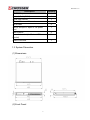
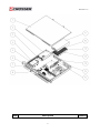
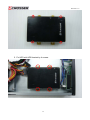
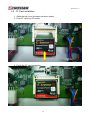
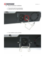
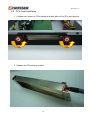
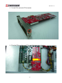
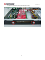
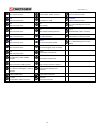
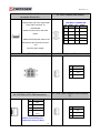
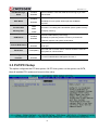
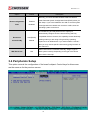
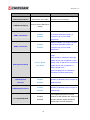
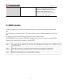
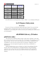
Revision: 1.2 AR-R5800 User Manual 1 Revision: 1.2 Copyright 2011 All Rights Reserved. Manual’s first edition: For the purpose of improving reliability, design and function, the information in this document is subject to change without prior notice and does not represent a commitment on the part of the manufacturer. In no event will the manufacturer be liable for direct, indirect, special, incidental, or consequential damages arising out of the use or inability to use the product or documentation, even if advised of the possibility of such damages. This document contains proprietary information protected by copyright. All rights are reserved. No part of this Manual may be reproduced by any mechanical, electronic, or other means in any form without prior written permission of the manufacturer. Trademarks AR-B5800 is a registered trademarks of Acrosser; IBM PC is a registered trademark of the International Business Machines Corporation; Pentium is a registered trademark of Intel Technologies Inc; Award is a registered trademark of Award Software International Inc; other product names mentioned herein are used for identification purposes only and may be trademarks and/or registered trademarks of their respective companies. Table of Contents 2 Revision: 1.2 System Installation Guide ..................................................5 1 Introduction to AR-R5800 ..............................................................5 1.1 1.2 1.3 Specifications................................................................................... 6 Packing List ..................................................................................... 6 System Dissection ........................................................................... 7 2 Procedures of Assembly/Disassembly ........................................11 2.1 2.2 2.3 2.4 2.5 2.5” HDD Installation.......................................................................11 CF Card Installation ....................................................................... 16 Power Cord Hook Installation ........................................................ 17 PCIe Card Installation .................................................................... 18 Rack Bracket Installation ............................................................... 21 Board Guide ......................................................................22 1 Introduction ..................................................................................23 1.1 1.2 1.3 Specifications................................................................................. 24 Package Contents ......................................................................... 25 Block Diagram ............................................................................... 26 2 H/W Information...........................................................................27 2.1 Locations (Top side).......................................................................... 27 2.2 Connectors and Jumper Setting ....................................................... 29 2.3 Connector and Jumper Setting ......................................................... 31 3 BIos setting ..................................................................................35 3.1 Main Setup........................................................................................ 36 3.2 Advanced Chipset Setup................................................................... 37 3.3 PnP/PCI Setup.................................................................................. 38 3.4 Peripherals Setup ............................................................................. 39 3.5 PC Health Setup ............................................................................... 41 3.6 Boot Setup ........................................................................................ 41 3.7 Exit Setup ......................................................................................... 42 3.8 BIOS Update..................................................................................... 44 4 Software Installation and Programming Guide ............................49 3 Revision: 1.2 4.1 4.2 4.3 Introduction .................................................................................... 49 File Descriptions ............................................................................ 51 API List and Descriptions .............................................................. 54 4 Revision: 1.2 AR-R5800 System System Installation Guide 1 Introduction to AR-R5800 5 Revision: 1.2 AR-R5800 series is a 1U height, rack-mounted platform for networking appliance, e.g. VPN, SSL, UTM or firewall. With Intel advanced Core 2 Quad / Duo / Pentium / Celeron CPU, AR-R5800 is a powerful platform to satisfy different applications. By eight 10/100/1000Mbps LANs, the AR-R5800 is sufficient for the small to middle size business security solution. AR-R5800 series can be equipped with 2 x HDD for RAID 0/1 redundancy. Customers don’t need to worry about data lost due to HDD defected problem. With LCM module, users can easily understand system status. BIOS, GPIO and Jumper can control LAN bypass feature. It provides flexibility to access Internet by user setting. It also has standard PCIe x 8 slot. Customers can purchase suitable add-on card to meet their appliance. Key features: 1. Support Intel Core 2 Quad or Core 2 Duo or Pentium or Celeron CPU 2. Intel G41 + ICH7R Chipset to support RAID 0/1 redundancy 3. DDRIII DIMM x 2, up to 4GB memory 4. Intel 82574L 10/100/1000Mbps x 6 + 82541PI 10/100/1000Mbps x 2 5. Two pairs LAN ports support bypass feature (LAN 1/2 + LAN 3/4) 6. LAN bypass can be controlled by BIOS, GPIO and Jumper 7. CF socket, 2.5” HDD x 2, SATA II interface x 2 8. Console, VGA (pinhead), USB 2.0 x 4 (2 x connectors, 2 x pin head) 9. Support boot from LAN, console redirection 10. Support standard PCIe x 8 slot for feature expansion 11. LCM module to provide user-friendly interface 12. Standard 1U rack mount size 1.1 Specifications Item Description System AR-R5800 CPU Board AR-B5800 System Dimensions 442.4x371.5x44(mm) 1.2 Packing List 6 Revision: 1.2 Description Quantity AR-R5800 system 1 Console Cable(RJ45) 1 Quick user manual 1 CD with Driver and Manual 1 SATA cable 2 USA or Europe or Japan or UK power cord 1 Rack bracket 2 Screw for bracket (for Rack + HDD bracket) 14 Power cord hook 1 1.3 System Dissection (1) Dimensions (2) Front Panel 7 Revision: 1.2 LCM Module Keypad Console Reset LEDs Lan*8 USB*2 (3) Back Panel PCIe x 8 slot (4) System Configuration 8 Power Inlet Revision: 1.2 Item Description 9 Quantity Revision: 1.2 1 TOP COVER 1 2 POWER SUPPLY 1 3 POWER BRACKET 1 4 HDD BRACKET 1 5 BOTTOM BASE 1 6 1U EAR BRACKET 2 7 MEMBRANE 1 8 AR-B5800 1 9 SHEET FLOW 1 10 FAN 2 11 CPU SINK 1 12 CPU SINK BKT 2 13 INTERFACE BKT 1 14 FAN 2 15 RISER CAR & BKT 1 10 Revision: 1.2 2 Procedures of Assembly/Disassembly 2.1 2.5” HDD Installation The following instructions will guide you to install 2.5” HDD step-by-step. 1. Unfasten 2 screws of chassis top cover and take off it. 2. Release HDD bracket by unfastening 4 screws. 11 Revision: 1.2 3. Take out HDD screws from packing bag. 4. Fix HDD with HDD bracket by 4 screws. 12 Revision: 1.2 5. Fix HDD with HDD bracket by 4 screws. 13 Revision: 1.2 6. Plug SATA power cable into motherboard. 7. The SATA power cable MUST go through below M/B power cable, please follow below photo. 14 Revision: 1.2 8. Connect SATA cable and SATA power cable with HDD module. 9. Assemble top cover back by fastening the 2 screws. 15 Revision: 1.2 2.2 CF Card Installation 1. Open the top cover (the same as above steps). 2. Push CF card into CF socket. 3. Finish the CF card installation. 16 Revision: 1.2 2.3 Power Cord Hook Installation 1. Take out the hook from packing bag. 2. Install the hook from right side firstly. 3. Then install the hook by left side. 17 Revision: 1.2 2.4 PCIe Card Installation 1. Unfasten two screws of PCIe bracket and then take out the PCIe card bracket. 2. Release the PCIe dummy bracket. 18 Revision: 1.2 3. Fix the PCIe card with PCIe bracket. 4. Plug the PCIe module into PCIe slot following below direction. 19 Revision: 1.2 5. Fasten the 2 screws in order to firm the PCIe module. 20 Revision: 1.2 2.5 Rack Bracket Installation 1. Take out the screws and Rack bracket from packing bag. 2. Fixed the Rack bracket to Chassis by fastening 6 screws. 21 Revision: 1.2 AR-B5800 Board Intel® Core™2 LGA775 PROCESSOR Networking Board Board Guide Manual Rev.: 1.0 Book Number: AR-B5800-2011.01.10 22 Revision: 1.2 1 Introduction AR-B5800 is designed for rack-mounted platform for networking appliance, e.g. VPN, SSL, UTM or firewall. With Intel advanced Core 2 Quad / Duo / Pentium / Celeron CPU, AR-B5800 is a powerful platform to satisfy different applications. By eight 10/100/1000Mbps LANs, the AR-B5800 is sufficient for the small to middle size business security solution. AR-B5800 can install 2 x HDD for RAID 0/1 redundancy. Customers don’t need to worry about data lost due to HDD defected problem. BIOS, GPIO and Jumper can control LAN bypass feature. It provides flexibility to access Internet by user setting. It also has standard PCIe x 8 slot. Customers can purchase suitable add-on card to meet their appliance. Key features: 1. Support Intel Core 2 Quad or Core 2 Duo or Pentium or Celeron CPU 2. Intel G41 + ICH7R Chipset to support RAID 0/1 redundancy 3. DDRIII DIMM x 2, up to 4GB memory 4. Intel 82574L 10/100/1000Mbps x 6 + 82541PI 10/100/1000Mbps x 2 5. Two pairs LAN ports support bypass feature (LAN 1/2 + LAN 3/4) 6. LAN bypass can be controlled by BIOS, GPIO and Jumper 7. CF socket, 2.5” HDD x 2, SATA II interface x 2 8. Console, VGA (pinhead), USB 2.0 x 4 (2 x connectors, 2 x pin head) 9. Support boot from LAN, console redirection 10. Support standard PCIe x 8 slot for feature expansion 23 Revision: 1.2 1.1 Specifications CPU: a LGA775 socket for Intel Core2 Processors in the 775-Land LGA package. DMA channels: 7. Interrupt levels: 16 (24 APIC interrupts). Chipset: Intel G41 express chipset 82G41 + 82801GR + W83627DHG-P. Memory: provides two 240-pin DIMM sockets to support DDRIII 1066 non-ECC DIMM. The memory capability can up to 2GB. VGA Controller: G41 GMCH integrated. Analog Display Interface: 10-pin box header, and resolution up to 2048x1536@75Hz. Serial ATA Interface: supports Two SATA devices, and data transfer rates up to 300MB/s per device. Compact flash interface: supports TYPE-II compact flash card with UDMA supported. USB2.0 interface: one stacked USB connector and two 10-pin pin header to support Six USB2.0 compatible devices. All resettable fuses protected. Ethernet interface: on-board six PCI express gigabit Ethernet controllers and two PCI gigabit Ethernet controllers to support eight LAN ports. They provide a standard IEEE 802.3 Ethernet interface for 1000BASE-T, 100BASE-TX, and 10BASE-T applications (802.3, 802.3u, and 802.3ab, respectively). BYPASS function: supports by ports LAN1 & LAN2 , LAN3 & LAN4 software programmable. PCIE X8 interface: One PCI Express x8 slot. Serial ports (RS232): One high-speed 16550 compatible UARTs ports with 16-byte send/receive FIFOs. COM1: RJ45 connector. LCM interface: a 7-pin pin header could be used to LCM for chassis’ control panel. General Purpose Input/Output: 8-bit, 3.3V TTL level, bidirectional, and software programmable GPIOs. WATCHDOG: software programmable 1~255 second(s) / minute(s). Power Consumption: +12V [5.3A], +5V [3.5A], +3.3V [1.8A], -12V [0.9A], +5Vsb [0.8A] typically. Test equipments list as below: Main board: AR-B5800. Processor: Intel Pentium Processor E6500 2.93GHz / FSB1066 / 2MB L2 cache / 45nm. 24 Revision: 1.2 Memory: one Kingston KVR1333D3N9/2G. One 3.5” HDD OS: Windows XP SP3. Processor was running at 100% loading. Note: A proper power supply unit choice means that we should consider at least about a.) Protection of overload, short-circuit, and other safeties. b.) Summation of all devices’ power requirements. c.) Thermal de-rating. 1.2 Package Contents Check if the following items are included in the package. In addition to this User's Manual, the AR-B5800 package includes the following items: A quick setup manual. One AR-B5800 networking board. One Software utility CD. One adaptable cable for COM1. One D-SUB-15 adaptable cable for VGA. One SATA cable. One USB adaptable cable. (Optional) (ACROSSER’s P/N.190030779-G) 25 Revision: 1.2 1.3 Block Diagram 26 Revision: 1.2 2 H/W Information This chapter describes the installation of AR-B5800. At first, it shows the Function diagram and the layout of AR-B5800. It then describes the unpacking information which you should read carefully, as well as the jumper/switch settings for the AR-B5800 configuration 2.1 Locations (Top side) 27 Revision: 1.2 RTC1 System RTC battery socket Intel ICH7R PCIEXP1 PCI-Express X8 Slot DIMM1 240-Pin DDR3 Socket LGA775 CPU Socket DIMM2 240-Pin DDR3 Socket Intel GMCH 82G41 28 Revision: 1.2 2.2 Connectors and Jumper Setting 2.2.1 Locations (Top side) 29 Revision: 1.2 LAN1 LAN1 RJ45 Connector FP_USB1 Internal USB2, USB3 connector. SYSFAN2 System FAN Connector. LAN2 LCM1 LAN2 RJ45 Connector Pin Header for LCM SYSFAN1 System FAN Connector. LAN3 GP1 GPIO Header. JP1 For LAN1/LAN2 Bypass Function Select. JP2 GPIO Header Voltage Selection. RTC1 CR2032 Battery Hold Connector. CF1 CF CARD SOCKET. CCMOS1 CMOS Memory Clearing Header LAN6 RJ45 Connector CPLD1 For CPLD Firmware Update JP4 For LAN3/LAN4 Bypass Function Select. LAN7 ATXPWR1 LAN7 RJ45 Connector. ATX Power Supply input connector.. LAN8 SATA2 SATA device connector #2. LAN3 RJ45 Connector LAN4 LAN4 RJ45 Connector. LAN5 LAN5 RJ45 Connector LAN6 LAN8 RJ45 Connector. USB1 Two USB ports (USB0, USB1) connector. SATA1 COM1 VGA1 RS232 Serial Port COM1.(RJ45) VGA connecter (2x5 Pin Header) LED1 4 in 1 LED for LAN Bypass, Power & HDD LED. ATX12V1 ATX12V Power Supply input Connector. RST2 System Reset Switch. SYSFAN3 System FAN Connector. FP_USB2 Internal USB4, USB5 connector. CPUFAN1 SATA device connector #1. CPU FAN Connector. 30 Revision: 1.2 2.3 Connector and Jumper Setting 1. LAN1 ~ LAN8 RJ45 Connector 9. USB1 Connector External USB Connector Connects to USB devices such as scanner, LAN RJ45 Connector digital speakers, monitor Connects to Local Area , mouse, keyboard, hub, digital camera, Network. 10. COM1 ( RJ45 Connector ) joystick etc. 11. LED1 Green1: Power ON LED. Green2: HDD LED COM Port RJ45 Connector Yellow1: LAN3&LAN4 Bypass LED. Yellow2: LAN1&LAN2 Bypass LED. 12. RST2 13,14. FP_USB1 & FP_USB2 Push this button to reset the system. 31 Revision: 1.2 15. LCM1 ( for LCM use ) 16. GP1 ( GPIO Header ) PIN SIGNAL PIN SIGNAL Pull-High to VCC5 1 VCC_GP 2 GND 2 VCC5 3 GP30 4 GP34 3 SOUTB 5 GP31 6 GP35 4 SINB 7 GP32 8 GP36 5 RTSB# 9 GP33 10 GP37 6 CTSB# 7 GND Pin SIGNAL 1 17. JP2 GPIO Header Voltage Selection 18. CF1 ( CF CARD Socket ) Pins 1 and 2 shorted (Default): VCC 5 Pins 2 and 3 shorted: VCC 3 19. CPLD1 ( for CPLD Firmware Update) Pin SIGNAL 1 3VDUAL 2 G_TDO 3 G_TDI 4 NC 5 NC 6 G_TMS 7 GND 8 G_TCK 20. ATXPWR1 ( ATX Power Supply Input ) 32 Revision: 1.2 21,22. SATA2, SATA1 (SATA device connector #2 and #1). 23. VGA1 (2x5pin 2mm Wafer). To connect SATA device: 1.Attach either end of the signal cable VGA Wafer CONNECTOR . to the SATA connector on PIN SIGNAL PIN SIGNAL motherboard. 1 Red 2 GND Attach the other end to the SATA 3 Green 4 GND 5 Blue 6 GND 7 VSYNC 8 DDCCLK 9 HSYNC 10 DDCDATA device. 2. Attach the SATA power cable to the SATA device and connect the other end from the power supply. 24. ATX12V1. (ATX12V Power Input) 25. SYSFAN3 (System FAN connector 3). SIGNAL 1 GND 2 +12V 3 Fan speed data SIGNAL 1 GND 2 +12V 3 Fan speed data 27. SYS_FAN2 (System FAN connector 2). 26. CPUFAN1 (CPU FAN connector). PIN PIN CPU FAN PWM 4 Control ON/OFF controlled by CPU temperature setting of BIOS. 33 PIN SIGNAL 1 GND 2 +12V 3 Fan speed data Revision: 1.2 28. SYS_FAN1 (System FAN connector 1). PIN SIGNAL 1 GND 2 +12V 3 Fan speed data 29. JP1 (For LAN1/LAN2 Bypass Function Select.). Pins 1 and 2 shorted (Default): Forced Normal. Pins 2 and 3 shorted: Controlled By CPLD. Otherwise : Forced Bypass 30. RTC1 31. CCMOS1. CMOS Backup Battery: An onboard battery saves the CMOS memory to keep the BIOS information stays on even after disconnected your system with power source. Nevertheless, this backup battery exhausts after some five years. Once the error message like “CMOS BATTERY HAS FAILED” or “CMOS checksum error” displays on monitor, this backup battery is no longer functional and has to be renewed 32. JP4 (For LAN3/LAN4 Bypass Function Select.). Pins 1 and 2 shorted (Default): Forced Normal. Pins 2 and 3 shorted: Controlled By CPLD. Otherwise : Forced Bypass 34 Revision: 1.2 3 BIOS setting This chapter describes the BIOS menu displays and explains how to perform common tasks needed to get the system up and running. It also gives detailed explanation of the elements found in each of the BIOS menus. The following topics are covered: Main Setup Advanced Chipset Setup Peripherals Setup PnP/PCI Setup PC Health Setup Boot Setup Exit Setup 35 Revision: 1.2 3.1 Main Setup Once you enter the Award BIOS™ CMOS Setup Utility, the Main Menu will appear on the screen. Use the arrow keys to highlight the item and then use the <Pg Up> <Pg Dn> keys to select the desired value in each item. Note: The control keys are listed at the bottom of the menu. If you need any help with the item fields, you can press the <F1> key, and the relevant information will be displayed. Option Choice Description Date Setup N/A Set the system date. Note that the ‘Day’ automatically changes when you set the date. Time Setup N/A Set the system time. N/A The onboard CF connectors provide one channel for connecting one CF CARD Only the BIOS will auto-detect the CF type. IDE Channel 0 Master 36 Revision: 1.2 The onboard SATA connectors provide 1 channel for connecting one SATA hard disks, the BIOS will auto-detect the SATA type. SATA Channel 1/2 N/A Halt On All Errors, No Errors, All but keyboard. Select the situation in which you want the BIOS to stop the POST process and notify you. 3.2 Advanced Chipset Setup This section allows you to configure and improve your system and follows you to set up some system features according to your preference. Option Choice Quick Power On Self Enabled Test Disabled Description This category speeds up Power On Self Test (POST) after you have powered up the computer. If it is set to Enable, BIOS will shorten or skip some check items during POST. 37 Revision: 1.2 Full Screen Logo Enabled Select Enabled to show the OEM full screen logo if you have Show Disabled add-in BIOS. APIC Mode Pre-allocated Memory Size DVMT Mode Console Redirection Enabled Disabled 32Mb 64Mb 128Mb Enabled Disabled Advanced Programmable Interrupt Controller.This item [Enabled] for more system INTerrupts that AR-B5800 required. This Item is for setting the Frame Buffer (Share system memory as display memory). Dynamic Video Memory Technology. [Enabled] for optimizing amount of memory is located for balanced graphics and system performance. Enabled [Enabled] for user who w ant to remote control the system via Disabled serial port. Baud Rate 115200(Max) LAN Bypass Enabled Function Disabled The baud rate of remote control machine should the same as the system for communication. For user Enable/Disable LAN Bypass Function !!. 3.3 PnP/PCI Setup The option configures the PCI bus system. All PCI bus system on the system use INT#, thus all installed PCI cards must be set to this value. 38 Revision: 1.2 Option Choice Description Normally, you leave this field Disabled. Select Enabled to Reset Configuration Enabled Data Disabled reset Extended System Configuration Data (ESCD) when you exit Setup. If you have installed a new add-on and the system reconfiguration has caused such a serious conflict, then the operating system cannot boot. The Award Plug and Play BIOS has the capacity to automatically configure all of the boot and Plug and Play Resources Auto(ESCD) Controlled By Manual compatible devices. However, this capability means absolutely nothing unless you are using a Plug and Play operating system such as Windows 95. If you set this field to “manual,” then you may choose specific resources by going into each of the submenus. When resources are controlled manually, assign a type to IRQ Resources N/A each system interrupt, depending on the type of the device that uses the interrupt 3.4 Peripherals Setup This option controls the configuration of the board’s chipset. Control keys for this screen are the same as for the previous screen. 39 Revision: 1.2 Option Choice Description Onboard Serial Port 1 Serial Port 1: 3F8 / IRQ4 Select an address and the corresponding Onboard Serial Port 2 Serial Port 2: 2F8 / IRQ3 interrupt for each serial port. USB Device Setting Enter to Select USB Device Setting Select Enabled if your system contains USB 1.0 Controller Enabled a Universal Serial Bus (USB) 1.0 Disabled controller and you have USB peripherals Select Enabled if your system contains USB 2.0 Controller Enabled a Universal Serial Bus (USB) 2.0 Disabled controller and you have USB peripherals Auto decide USB device operation mode. [High Speed]: If USB device was high speed device, then it operated on high USB Operation Mode Full/Low Speed High Speed speed mode. If USB device was full/Low speed device, then it operated on full/low speed mode. [Full/Low Speed]: All of USB device operated on full/low speed mode. USB Keyboard Enabled [Enable] or [Disable] Legacy Support of Function Disabled USB Keyboard Enabled [Enable] or [Disable] Legacy Support of Disabled USB Storage USB Storage Function The integrated peripheral controller On chip IDE DEVICE Enabled contains an IDE interface with support for Disabled two IDE channels. Select Enabled to activate each channel separately. 40 Revision: 1.2 3.5 PC Health Setup This section shows the parameters in determining the PC Health Status. These parameters include temperatures, fan speeds, and voltages. 3.6 Boot Setup This section is used to exit the BIOS main menu. After making your changes, you can either save them or exit the BIOS menu and without saving the new values. 41 Revision: 1.2 Option Choice Description Hard Disk First / Second / Third Boot Device/Other Boot Device CDROM USB-FDD USB-CDROM LAN The BIOS attempts to load the operating system from the devices in the sequence selected in these items. Disabled LAN Boot Select Hard Disk Boot Priority Enabled These fields allow the system to search Disabled for an OS from LAN These fields set the Boot Priority for each N/A Hard Disk 3.7 Exit Setup This section is used to configure exit mode. 42 Revision: 1.2 Option Choice Description Press “Y” to store the selections made in Pressing <Enter> on this item for confirmation: the menus in CMOS – a special section of memory that stays on after you turn your system off. The next time you boot your Save & Exit Setup Save to CMOS and EXIT (Y/N)? Y computer, the BIOS configures your system according to the Setup selections stored in CMOS. After saving the values the system is restarted again When you press <Enter> on this item you get a Load Optimized Defaults confirmation dialog box with a Press ‘Y’ to load the default values that are message like this: factory-set for optimal-performance system operations. Load Optimized Defaults (Y/N)? N Exit Without Saving Pressing <Enter> on this item This allows you to exit Setup without storing for confirmation: any changes in CMOS. The previous selections remain in effect. This shall exit Quit without saving (Y/N)? Y the Setup utility and restart your computer. When a password has been enabled, you will be prompted to enter your password every time you try to enter Setup. This prevents unauthorized persons from changing any part of your system configuration. Pressing <Enter> on this item Type the password, up to eight characters for confirmation: in length, and press <Enter>. The password Set Password typed now will clear any previous password ENTER PASSWORD: from the CMOS memory. You will be asked to confirm the password. Type the password again and press <Enter>. You may also press <Esc> to abort the selection and not enter a password. To disable a password, just press <Enter> 43 Revision: 1.2 when you are prompted to enter the password. A message will confirm that the password will be disabled. Once the password is disabled, the system will boot and you can enter Setup freely. 3.8 BIOS Update The BIOS program instructions are contained within computer chips called FLASH ROMs that are located on your system board. The chips can be electronically reprogrammed, allowing you to update your BIOS firmware without removing and installing chips. The AR-B5800 provides the FLASH BIOS update function for you to easily to update BIOS. Please follow these operating steps to update BIOS: 44 Revision: 1.2 APPENDIX A. MEMORY MAP 45 Revision: 1.2 APPEXDIX B. IRQ MAP 46 Revision: 1.2 APPENDIX C. I/O PORT MAP 47 Revision: 1.2 48 Revision: 1.2 Software Installation and 4 Programming Guide 4.1 Introduction LCD Control Module Overview The LCM (short for LCD Control Module) APIs provide interfaces to control the module. By invoking these APIs, programmers can implement the applications which have the functions listed below: 1. 2. 3. 4. 5. 6. Clear LCD screen. Turn on or off the cursor on the screen. Move the cursor on the screen. Turn on or off the text on the screen. Get the identification of the pressed key of the LCM. Show the text on the screen. GPIO and Watchdog Overview AR-B5800 provides both a GPIO interface and a Watchdog timer. Users can use the GPIO and Watchdog APIs to configure and to access the GPIO interface and the Watchdog timer. The GPIO has eight ports. Users can configure each pin as input or output respectively. The Watchdog timer can be set to 1~255 seconds. Setting the timer to zero disables the timer. The remaining seconds of the timer to reboot can be read from the timer. In this GPIO and Watchdog package, we provides: 1. API source code. 2. GPIO and Watchdog test utility and the utility source code. Here is the GPIO Mapping Table: 49 Revision: 1.2 Pin Name on SIO I/O Direction Signal Name in Source Code GP30 Configurable GPIO0 GP31 Configurable GPIO1 GP32 Configurable GPIO2 GP33 Configurable GPIO3 GP34 Configurable GPIO4 GP35 Configurable GPIO5 GP36 Configurable GPIO6 GP37 Configurable GPIO7 In the GPIO APIs, we use the signal names ‘GPIO0’, ‘GPIO1’…etc. to identify the GPIO ports. LAN Bypass Subsystem Overview Two pairs of LAN ports on AR-B5800 implement the bypass function. Users can invoke the LAN Bypass APIs to control the bypass states of the LAN ports and set up the LAN Bypass Watchdog timer ( this watchdog timer is different from the system watchdog timer mentioned in the previous paragraph ). AR-B5800 Library (Window platform only) The released code for Windows platform includes a folder called ‘AR-B5800’. In this folder, there are header files and source codes of all the APIs of LCM module, GPIO, Watchdog, and LAN Bypass functions. The source codes in this folder generate the API library ‘AR-B5800.lib’ and ‘AR-B5800.dll’. Users who want to invoke the APIs can include the ‘AR-B5800.h’ in their application source code and compile their application with the library ‘AR-B5800.lib’ or ‘AR-B5800.dll’. Besides AR-B5800 libraries, there are WinIo32.sys, WinIo32.lib, and WinIo32.dll in this directory. These files are indispensable for LAN Bypass application, GPIO and Watchdog application. Please put these three files with LAN Bypass application, GPIO and Watchdog application in the same folder. The APIs invoke WinIo32.lib, WinIo32.dll, and WinIo32.sys implicitly. 50 Revision: 1.2 4.2 File Descriptions LCD Control Module On Linux platform: 1. lcmdemo.c This file is the source code of the demo program. This program displays the user interface, processes user’s input, and invokes LCM APIs to demonstrates the functions of LCM. 2. lcm.c This file includes the hardware independent implementation of LCM APIs. All the APIs in this file invoke the hardware dependent functions ‘InitSerialPort( )’, ‘WriteSerial( )’, ‘ReadSerial( )’ and ‘CloseSerialPort( )’ for accessing the serial port 3. lcm.h This file includes the declarations and macro definitions needed by lcm.c. 4. serialport.c This file includes the hardware dependent implementation of ‘InitSerialPort( )’, ‘WriteSerial( )’, ‘ReadSerial( )’ and ‘CloseSerialPort( )’ for accessing the serial port. 5. serialport.h This file includes the declarations and macro definitions needed by serialport.c. 6. Makefile This is the instruction script for GNU make system. On Window platform: 1. LCM.cpp The source code of the LCM demo program. 2. AR-B5800.h The header of the APIs. 3. AR-B5800.lib and AR-B5800.dll The API libraries. 51 Revision: 1.2 GPIO and Watchdog On Linux platform: 1. sio_acce.c The source code of the Watchdog and GPIO APIs for accessing the SuperIO. 2. sio_acce.h This file includes the declarations of the APIs and macro definitions. 3. main.c The source code of the utility. 4. Makefile On Windows platform: 1. GPIO_Watchdog.cpp GPIO and Watchdog demo program source code. 2. AR-B5800.h The header file of the APIs. 3. AR-B5800.lib and AR-B5800.dll The API libiaries. LAN Bypass Subsystem On Linux platform: 1. bypass.c The source code of the APIs for setting up the bypass state. 2. bypass.h This file includes the declarations of the APIs and macro definitions. 3. main.c The source code of the utility. 4. Makefile 52 Revision: 1.2 On Windows platform: 1. LAN_Bypass.cpp LAN_Bypass demo program source code. 2. AR-B5800.h The header file of the APIs. 3. AR-B5800.lib and AR-B5800.dll The API libiaries. 53 Revision: 1.2 4.3 API List and Descriptions Type Definitions Typedef Typedef Typedef Typedef Typedef Typedef char unsigned char short unsigned short unsigned long int i8; u8; i16; u16; u32; i32; LCD Control Module 1. i32 clrscrLcm( void ) Description: Clear the screen of the LCM. Return value: 0 after the screen is cleared. 2. i32 cursorLcm( bool mode ) Description: According to the argument ‘mode’, show the cursor on the LCM screen or eliminate the cursor on the LCM screen. The position of the cursor is unchanged. mode = true, show the cursor. mode = false, eliminate the cursor. Return value: 0 after the cursor has been shown or eliminated. 3. i32 cursorActionLcm( i32 type) Description: According to the argument ‘type’, move the cursor to the indicated position. The displayed text is not altered. type = HOME, move the cursor to row 0, column 0. type = MOVERIGHT, move the cursor to the column which is to the right of its original position if the original column < 15. type = MOVELEFT, move the cursor to the column which is to the left of its original position if the original column > 0. type = MOVEBACK, move the cursor to the column which is to the left of its original position and delete the character at the new position if the original column > 0. Return value: 0 after the cursor is moved. 54 Revision: 1.2 4. i32 displayLcm( bool mode ) Description: Show the text on the LCM screen or eliminate the text on the LCM screen. The content of the text is not altered. mode = true, show the text. mode = false, eliminate the text. Return value: 0 after the text has been shown or eliminated. 5. i32 getKeyLcm( void ) Description: Scan the LCM and return the identification of the pressed direction key. Return value: ‘UP’ if the ‘up’ direction key is pressed. ‘RIGHT’ if the ‘right’ direction key is pressed. ‘LEFT’ if the ‘left’ direction key is pressed. ‘DOWN’ if the ‘down’ direction key is pressed. ‘NONE’ if none of the keys is pressed. 6. i32 getPositionLcm( i32 *row, i32 *column ) Description: Get the position of the cursor and write the coordinate to the memory pointed at by arguments ‘row’ and ‘column’. Return value: 0 if the request for the coordinate has been served. 7. i32 setPositionLcm( i32 row, i32 column ) Description: Set the position of the cursor according to the arguments ‘row’ and ‘column’. Return value: 0 after the position has been set. -1 if the argument ‘row’ or ‘column’ meets any of the following conditions: (1) row is not 0. (2) row is not 1. (3) column is less than 0. (4) column is greater than 15. 8. i32 showLcm( i32 length, u8 *info ) Description: Start from the current position of the cursor; print the text pointed at by ‘info’ to the LCM screen. The number of characters to be printed is at most ‘length’. If the remaining columns available for printing the text is less than ‘length’, the number of the characters to be printed is: 16 – ( column number of the current position of the cursor ). Return value: 0 after the text is printed. 55 Revision: 1.2 GPIO and Watchdog GPIO 1. Syntax: i32 setChDir( u8 val ) Description: Set the direction (Input/Output) of GPIO ports according to the parameter ‘val’. Parameters: The parameter ‘val’ is an unsigned character. Each bit of *val corresponds to a GPIO port. Bit 0 corresponds to GPIO0. Bit 1 corresponds to GPIO1. Bit 2 corresponds to GPIO2, and so on. Setting a bit of ‘val’ as 0 configures the corresponding port as Output. Setting a bit of ‘val’ as 1 configures the corresponding port as Input. Return Value: If the function gets the configuration successfully, it returns 0. If any error, it returns –1. 2. Syntax: i32 getChDir( u8 *val ) Description: Get the direction (Input/Output) of GPIO ports and put the configuration at *val. Parameters: The parameter ‘val’ points to an unsigned character. Each bit of *val corresponds to a GPIO port. Bit 0 corresponds to GPIO0. Bit 1 corresponds to GPIO1. Bit 2 corresponds to GPIO2, and so on. A ‘0’ bit at *val indicates the corresponding port is an Output port. A ‘1’ bit at *val indicates the corresponding port is an Input port. Return Value: If the function gets the configuration successfully, it returns 0. If any error, it returns –1. 3. Syntax: i32 getChLevel( u8 *val ) Description: Get the status value of GPIO ports 0~7 and put the value at *val. Parameters: The parameter ‘val’ points to an unsigned character. If a GPIO port is configured as an Output port, the bit at *val which corresponds to this port indicates this port is outputting a ‘1’ or ‘0’. If a GPIO port is configured as an Input port, the corresponding bit at *val is always ‘1’. 56 Revision: 1.2 Return Value: If the function gets the values successfully, it returns 0. If any error, it returns –1. 4. Syntax: i32 setChLevel( u8 val ) Description: Set the status bits of GPIO Output ports according to the variable ‘val’. The status bits at the ports which are configured as input will not be affected. Parameters: The parameter ‘val’ is an unsigned character. If a GPIO port is configured as an Output port, a ‘1’ bit at ‘val’ directs the corresponding port to output a ‘1’. A ‘0’ bit directs this port to output a ‘0’. If a GPIO ports is configured as an Input port, the setting to these input port is ignored. Return Value: If the function sets the values successfully, it returns 0. If any error, it returns –1. Watchdog 1. Syntax: u8 getWtdTimer(void) Description: This function read the value of the watchdog time counter and return it to the caller. Parameters: None. Return Value: This function return the value of the time counter and return it to the caller as an unsigned integer. 2. Syntax: void setWtdTimer( u8 val ) Description: This function sets the watchdog timer register to the value ‘val’ and starts to count down. The value could be 0 ~ 255. The unit is second. Setting the timer register to 0 disables the watchdog function and stops the countdown. 57 Revision: 1.2 Parameters: The parameter ‘val’ is the value to set to watchdog timer register. The range is 0 ~ 255. Return Value: None. LAN Bypass Subsystem 1. void enableWdt(void) Enable Watchdog Timer. (This timer is different from the System Watchdog timer, which is configured by the API described in 6.2). 2. void disableWdt(void) Disable Watchdog Timer. 3. void reloadWdt(void) Reload Watchdog Timer. 4. void forceNormal(void) Force the port to become normal state. 5. void forceBypass(void) Force the port to become bypass state. 6. void setWdt4(void) Set the watchdog timer to 4 seconds. 7. void setWdt8(void) Set the watchdog timer to 8 seconds. 8. void setWdt16(void) Set the watchdog timer to 16 seconds. 9. void setWdt32(void) Set the watchdog timer to 32 seconds. 58