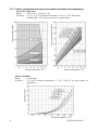
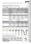
1
Rack mount environment monitor H3531R H4531R H7531R Monitoring of temperature, humidity, barometric pressure and other derived humidity values with Ethernet interface Instruction Manual Table of content 1. GENERAL SAFETY RULES ........................................................................ 4 2. GENERAL DESCRIPTION .......................................................................... 5 3. MONITORING SYSTEM MOUNTING AND CONNECTION ............... 6 4. PREPARATION TO OPERATION ............................................................. 8 4.1. PROCEDURE OF INSTRUMENT CONNECTION .................................................................8 5. DIMENSIONS ................................................................................................. 9 6. INSTALLATION .......................................................................................... 10 6.1. INSTALLATION PROCEDURE .......................................................................................10 7. OPERATION CHECKING ......................................................................... 11 7.1. 7.2. VISUAL CHECK...........................................................................................................11 COMMUNICATION CHECK VIA A LAN........................................................................11 8. DESCRIPTION OF DEVICE FUNCTION AND SETTING ................... 12 8.1. 8.2. 8.3. 8.4. RELAY OUTPUTS ........................................................................................................12 BINARY INPUTS ..........................................................................................................12 ACTUAL MONITORING SYSTEM PRESET – MEASUREMENT PART ................................12 MONITORING SYSTEM SETTING CHANGE – PART OF MEASUREMENT UNIT ................14 8.4.1. 8.4.2. 8.4.3. Setting with PC and TSensor software ................................................................................ 14 Setting with using monitoring system keys .......................................................................... 14 Extended setting mode ......................................................................................................... 14 8.5. 8.6. 8.7. RESTORE TO „FACTORY DEFAULT“ – MEASUREMENT PART ......................................19 MONITORING SYSTEM CONFIGURATION – ETHERNET INTERFACE .............................19 ALARMS – ETHERNET INTERFACE .............................................................................19 8.7.1. 8.7.2. Analogue values ................................................................................................................... 19 Binary values ....................................................................................................................... 20 8.8. FACTORY DEFAULT – ETHERNET INTERFACE ............................................................21 9. COMMUNICATION PROTOCOLS.......................................................... 22 9.1. 9.2. 9.3. 9.4. 9.5. 9.6. 9.7. MODBUS PROTOCOL ..................................................................................................22 SMTP ........................................................................................................................24 SNMPV1....................................................................................................................24 WWW........................................................................................................................25 SNTP .........................................................................................................................25 SYSLOG PROTOCOL ....................................................................................................25 SOAP .........................................................................................................................25 10. WHAT TO DO WHEN…............................................................................. 26 10.1. 10.2. 10.3. 10.4. I FORGOT THE IP ADDRESS OF THE DEVICE ................................................................26 IT IS NOT POSSIBLE TO CONNECT TO THE DEVICE FROM A LAN ................................26 LCD DISPLAY IS OFF .................................................................................................26 ERROR STATES OF THE DEVICE ..................................................................................26 11. READINGS ON LCD DISPLAY................................................................. 28 2 IE-HGS-HX531R-07 12. PREVENTIVE MAINTENANCE ............................................................... 29 13. TECHNICAL SPECIFICATION................................................................ 30 13.1. TECHNICAL PARAMETERS ..........................................................................................30 13.1.1. Common parameters ............................................................................................................ 30 13.1.2. Accuracy, range and resolution of monitoring systems ....................................................... 30 13.1.3. Value computed from measured relative humidity and temperature ................................... 32 13.2. 13.3. 13.4. OPERATING CONDITIONS ...........................................................................................33 END OF OPERATION....................................................................................................33 TECHNICAL SUPPORT AND SERVICE ...........................................................................33 14. APPENDIX A ................................................................................................ 34 15. APPENDIX B................................................................................................. 34 Models marked HxxxxZ are non-standard versions of the devices. Description is not included in this manual. Copyright: COMET System, Ltd. It is prohibited to copy and edit this instruction manual and make any changes at all without explicit agreement of COMET System, Ltd. All rights reserved. COMET System, Ltd makes constant development and improvement of all its products. That is why it reserves the right to make any technical changes on the device/product without previous notice. IE-HGS-HX531R-07 3 1. General safety rules The following summary is designed to prevent injury hazards or device damage. Operate the instrument in accordance with this manual to prevent electric trauma. Service should be performed by a qualified person only. Use a safety ac/dc adapter. Use only an adapter with the power voltage recommended by its manufacturer and which is approved by proper standards. Check that the adapter has undamaged cables and cover. Connect and disconnect correctly. Do not connect and disconnect a LAN cable or lead-in cables if the device is under electric voltage. Do not use the instrument without the cover. Do not use the instrument, if it does not work correctly. If the instrument seems not to work correctly, have it checked by a qualified service person. Do not use the instrument in an explosive environment. Read instruction manual before the first device connection, please. 4 IE-HGS-HX531R-07 2. General description Monitoring systems of Hx531R line are designed for online monitoring of temperature in °C or °F, relative humidity of air without aggressive ingredients, barometric pressure and three binary inputs for detection of binary signals. Measured temperature and relative humidity are recomputed to following humidity expression: dew point temperature, absolute humidity, specific humidity, mixing ratio and specific enthalpy. It is possible to set correction for altitude (pressure offset) and to choose one of the following pressure units: hPa, kPa, mbar, mmHg, inHg, inH2O, PSI, oz/in2. The device is equipped with two relay outputs for alarming or controlling of external devices. It is possible to assign any input value to each relay, to set comparing limit, delay, hysteresis and acoustic alarm or change its status by far control with using of Modbus communication protocol. The device is communicating through Ethernet interface. The device is internally separated into two units. The first unit provides measurement and controlling of output relays – there is possible to change these parameters directly through device’s keys or TSensor software. The second unit provides all Ethernet services, its configuration is possible through Telnet terminal or TSensor software (this setting is impossible to change through device’s keys). Type H3531R H4531R */ H7531R Temperature Humidity Pressure Computed value Binary inputs 3x 3x 3x */ the type H4531R is designed for two wires connection of external Pt1000/3850 ppm temperature sensor. Measured values are available from Ethernet interface or are displayed on LCD display. If there are two values displayed at one LCD line, they are periodically switched between both readings with period of 4 seconds. Display can be switched OFF totally too. The following formats are supported: WWW pages with user-design possibility Modbus protocol SNMPv1 protocol SOAP The instrument may send a warning message to several defined points if the measured value gets out of adjusted limits. There are the following possible ways to deliver the warning report: to send an e-mail to maximum of three e-mail addresses to send a SNMP trap to maximum of three IP addresses to display an alarm state on the device WWW page to send a message to Syslog server Alarm limits may be set via TSensor software, Modbus, Telnet or a SNMPv1 protocol. The alarm state may be read via the device WWW pages, Modbus or the SNMPv1 protocol. The value assign to each relay is possible through TSensor software or through device’s keys. If Power over Ethernet is needed, it is necessary to use some PoE Splitter. Tested is e.g. D-Link DWL-P50. Device itself does NOT support PoE internally! Monitoring system supports Internet protocol version 4 (IPv6 is NOT supported). IE-HGS-HX531R-07 5 3. Monitoring system mounting and connection The devices are designed for mounting into 19-inch rack (mounting screws and female screws included). At back side of the device there are connectors for power source, 24pins CAGE CLAMP connector and RJ-45 Ethernet connector. There is possible to use +12V and +5V power output for powering of external sensors and detectors – see picture below. It is NOT recommended to use the device for long time under condensation conditions. It could be the cause of water steam condensation inside the sensor’s cover into water phase. This liquid phase stays inside sensor’s cover and can’t escape from the cover easily. It can dramatically increase response time to relative humidity change. If water condensation occurs for longer time it can cause sensor damage. Similar effect can occur under water aerosol conditions. External temperature probe connectable to H4531R must be type of “two wires with shielding”. The probe cable length and size of conductor affects measurement accuracy. If connected probe is equipped with metal stem, we recommend using probes with metal stem not connected to cable shielding. Or else it is necessary to arrange metal stem is not connected to any other circuitry. Binary inputs are designed for dry contact or external voltage connection – see picture 6 IE-HGS-HX531R-07 The maximal length of binary inputs and external Pt1000 temperature probe (H4531R only) is 10 m. Connect probe cable shielding to proper terminal and do not connect it to any other circuitry and do not ground it. The cables for binary inputs and external sensor must be placed as far as possible from potential interference sources. It is possible to connect optionally accessory, for more information see www.cometsystem.cz. Method of connection is shown in Appendix B of this document. Electrical system (wiring) may be done only by a worker with required qualification by rules in operation. IE-HGS-HX531R-07 7 4. Preparation to operation To provide all Hx531R monitoring systems functions it is necessary to make its setting through PC to satisfy your requirements. Requested parts necessary for operation: ac/dc adapter 12V RJ-45 LAN connection free IP address in your network temperature probe with a Pt1000 sensor for the H4531R monitor Contact network administrator to get free IP address. Warning! Reliability of warning messages reception (e-mail, trap) depends on current accessibility of required network services. It is recommended to protect device from unauthorized access to device settings and cables connection. 4.1. Procedure of instrument connection The cables and temperature probe for H4531R connect in order as shown in the pictures. After power supply connection, make monitoring system configuration. Connection of H3531R and H7531R Connection of H4531R 8 IE-HGS-HX531R-07 PoE splitter 5. Dimensions IE-HGS-HX531R-07 9 6. Installation It is necessary to assign a new suitable IP address to the device at the first connection to it in order to prevent collisions with already existing network IP addresses, and make the address conform to the local habits. If installing several new devices, connect them to the network one after another! If a suitable IP address is not known, contact your network administrator and ask him for the following: IP address of monitor IP address of gateway Network mask _____._____._____._____ _____._____._____._____ _____._____._____._____ The IP gate address and the network mask need not be specified if the device will be operated only in a local network. If you set the IP address to one which is already used in the network the device will NOT work correctly and collisions in the network will appear. It is possible to set the IP address by DHCP server. Device setting from the manufacturer: IP address: Gateway: Value assigned to relay 1 and relay 2: Password for setting through keys (PASS): Password for setting via TSensor: Value shown at first LCD line: Value shown at second LCD line: Temperature unit: Pressure unit: Correction for altitude: Computed value preset: Relay response for error: Signalization of binary inputs status: Acoustic alarm: 192.168.1.213 not set none 0000 none temperature (temperature/pressure) relative humidity/dew point temperature °C hPa 0 hPa (absolute pressure) dew point temperature stay unchanged at previous condition LED diode lights if input contact is open off 6.1. Installation procedure run TSensor software (default monitoring system IP address is 192.168.1.213) or use command line at PC with command „telnet 192.168.1.213 9999“. Telnet provides to set all Ethernet services. For setting of measurement and controlling of output relays use keys – see chapter 8.4. assign new device IP address make your own device setting by your requirements (alarm settings, used units, email and trap sending ...) save setting 10 IE-HGS-HX531R-07 7. Operation checking 7.1. Visual check When power source is on, there are actually measured values shown on LCD display (if the LCD has not been switched off). When Ethernet cable is connected, there is one light on its connector lighting. 7.2. Communication check via a LAN Open a browser of www pages and enter the devices IP address into appropriate field. Example: http://192.168.1.213 Monitoring system shows its name, serial number, measured values, alarm status and alarm settings or shows message Access denied in case of web pages are disabled or setting through Telnet is in operation. IE-HGS-HX531R-07 11 8. Description of device function and setting Information from device is available directly through LCD or you can read them with one of next communication protocols. For communication through some communication protocol (SNMPv1, Modbus, SOAP) there is necessary to have installed appropriate software supporting appropriate communication protocol on PC. Such software is not included in the delivery! The device is internally separated into two units. The first unit provides measurement and controlling of output relays – these parameters are possible to change directly through device’s keys or TSensor software. The second unit provides all Ethernet services, its configuration is possible through TSensor software or Telnet terminal (this setting is impossible to change through device’s keys). 8.1. Relay outputs Monitoring system is equipped with two relay outputs. It is possible to assign any input or computed value or “far control” to each relay, to set comparing alarm limit, if the relay may close if measured value is higher (Hi) or lower (Lo) than preset limit, delay for while must be preset condition true before relay close its contact and hysteresis for return to open status. For binary inputs: if it is preset to „HI“ then output relay is closed when input contact is opened, if it is preset to „Lo“ then output relay is closed when input contact is closed. Each relay status is indicated with LED diode and shown on LCD with corresponding symbols „ “ or „ “. 8.2. Binary inputs It is possible to read three binary inputs status. It is possible to connect “open contact” or external voltage. Visualization of binary inputs is done by three LED diodes placed on the left side from LCD. Green one represents input Binary 1, yellow input binary 2 and red input binary 3. Configuration of binary inputs is done by DIP switch one to three placed at backside of the device. DIP switch 1 is assigned to binary input 1, DIP2 to BIN2, DIP3 to BIN3. If corresponding DIP switch is ON, then appropriate binary input is configured as “voltage input”. It means that without connection of external voltage there is binary input read as “0”, after external voltage is applied, there is binary input read as “1”. This setting is for suitable for optional accessory “Power detector SP008” for example. If corresponding DIP switch is OFF, then appropriate binary input is configured as “dry contact input”. It means that if the binary input is open/disconnected then binary input status is read as “1”, if the binary input is closed (closed contact) then binary input status is read as “0”. For each binary input there is possible to set indication LED function – if is lighting when binary input is closed or opened. Binary input status can be assigned to any of output relays. It is possible to choice if output relay is closed or opened when binary input is closed/opened. Binary inputs are not galvanic isolated. 8.3. Actual monitoring system preset – measurement part It is NOT possible to make any changes of Ethernet services, for their setting see chapter 8.6 at page 19. If output relay alarm condition configuration is made using Modbus protocol, keyboard is blocked for this time. During this configuration is a word “bloc” shown in the display. 12 IE-HGS-HX531R-07 IE-HGS-HX531R-07 13 It is possible to display actual device preset on its LCD display by pressing of „“ key. LCD shows information about relay 1 and then relay 2 setting step by step. Information about relay 1 are indicated with symbol „ “, for relay 2 with symbol „ “ (at right top corner of LCD). It is possible to edit parameters after pressing „SET“ key and entering of correct password „PASS“ – see chapter 8.4.2 at page 14. Following examples are for relay 1 setting, similarly are displayed values for relay 2. Pressing of „ESC“ key ends this mode and switch to actual value displaying, the same occur if more than 20 s is not pressed any key. 8.4. Monitoring system setting change – part of measurement unit 8.4.1. Setting with PC and TSensor software User’s software TSensor is available free to download at web page www.cometsystem.cz. It provides setting of all device parameters. Run the TSensor program and follow the program instructions. Device includes hardware write protection of internal setting (except of Ethernet setting which is protected by password), new setting is possible to write only while: during write period press „SET“ key – do requested setting in TSensor software, press „SET“ key on device and keep it down, then click on the button „Save Changes“ into TSensor software and after end of write release „SET“ key, or 2. when DIP switch 4 is ON – available at back side of the device, if it is ON then you can see small number 3 at left side of LCD and new setting can be write. Don’t forget to move DIP switch 4 to OFF after setting procedure finish (restore write protection). TSensor software supports to make the adjustment of the device too. This procedure is described at file „Calibration manual.pdf“ which is installed commonly with the software. 1. 8.4.2. Setting with using monitoring system keys If „Actual monitoring system preset” is displayed (see chapter “Actual monitoring system preset – measurement part” at page 12), it is possible to enter into edit mode and edit displayed value by pressing „SET“ key. Then you are asked for valid password (PASS). If password is not valid there is shown for short time message “Err9” on LCD. You can edit selected value if right password is entered. During value editing there is range check executed and edited value is still compared with limits for corresponding value (range). If inserted value is higher or lower then edited number is automatically changed to its maximum / minimum value – for possible range see chapter „Technical parameters“ at page 30. Value can be changed with using „“ and „“ keys. Edited value is switched in “round” -9, -8, -7, …-2, -1, 0, 1, 2, …8, 9. To edit next number digit press „SET“ key, for moving back to previous digit press „ESC“ key. Edited value is stored by next „SET“ key pressing. It is possible to cancel editing by pressing „ESC“ key if necessary. If valid password is once inserted right, then there is possible to edit next items without asking for password insertion again, till “Actual monitoring system preset” is left (till actual measured values are shown). With new entering into edit mode it is necessary to enter Password again. Default password setting is preset from manufacturer to 0000, password change is possible into „Extended setting”. During edit mode device still works and changes are valid immediately after its storing. After storing the Ethernet part is restarted automatically. 8.4.3. Extended setting mode During device operation it is possible to change parameters available through “Actual monitoring system preset” only (see chapter 8.3 at page 12). Rest of device parameters are available 14 IE-HGS-HX531R-07 through “Extended setting mode”. In this mode device does NOT communicate, does NOT do any measurements and does NOT service output relays. To leave this mode press „ESC“ key and move DIP switch 4 to OFF. To enter into Extended setting mode do following steps: 1. disconnect power supply 2. move DIP switch 4 to ON (you should see small number 3 at left side of LCD) 3. press „“ and „“ keys together and keep them down 4. connect power supply to device – you should see message „SEL“ on the top line of LCD and on the bottom line you should see number of Firmware version (e.g. 0404) 5. release „“ and „“ keys – you are into “Extended setting mode” now Use „“ and „“ keys to inspect each items. If you want to change some shown item then press „SET“ key, item starts blink. Now you can edit setting with using „“ and „“ keys. To store preset value press „SET“ key. Press „ESC“ key to leave editing (changing) without save – last stored value is kept. Into this mode you can set following items: Acoustic alarm assign to relay 1 acoustic indication of relay 1 is OFF Acoustic alarm assign to relay 2 acoustic indication of relay 2 is OFF Acoustic alarm deactivation activated acoustic alarm is possible to deactivate by pressing „ESC“ key close of relay 1 indication contact starts acoustic close of relay 2 indication contact starts acoustic acoustic alarm is still activated for all time and it is impossible to deactivate it Relay response for error Monitoring system continuously checks its state during operation. In case error of assigned value measurement is found then output relay: IE-HGS-HX531R-07 15 stays unchanged (in previous status) stays unchanged (in previous status) relay 1 switch OFF relay 1 switch On relay 2 switch OFF relay 2 switch On Change of “Password for setting through keys” (PASS) This item shows actual password setting. It is possible to change it after „SET“ key pressing. It is number from range -19999 to +19999. password setting Visualization of binary inputs Visualization of binary inputs is done by three LED diodes. This option defines at which binary input status should LED diode indication lights – LED diode lights if binary input is OPEN or CLOSED. LED lights if binary input is OPEN LED lights if binary input is CLOSED Temperature unit choice It is possible to measure temperature at °C or °F. There is shown preset unit. It is possible to change it after „SET“ key pressing. preset to °C 16 preset to °F IE-HGS-HX531R-07 Barometric pressure unit choice It is possible to measure barometric pressure at hPa, PSI, inHg, mBar, oz/in2, mmHg, inH2O and kPa. There is shown preset unit. It is possible to change it after „SET“ key pressing. preset to hPa preset to PSI preset to inHg preset to mBar preset to oz/in2 preset to mmHg preset to inH2O preset to kPa Setting of pressure correction for altitude If is there necessary to read value of barometric pressure corrected with respect to altitude, it is possible to set corresponding pressure offset for this altitude. It is possible to change it after “SET” key pressing. Pressure correction value is then automatically added to measured pressure value. See chapter “Error States of the device” at page 26, Error 2. correction for altitude pressure correction value is from -25,0 to 650,0 hPa -0,363 to 9,427 PSI -0,74 to 9,19 inHg -25,0 to 650,0 mBar -5,8 to 150,8 oz/in2 -18,8 to 487,5 mmHg -10,0 to 261,0 inH2O -2,5 to 65 kPa Show temperature at LCD display This item provides to choice if actual measured temperature may be displayed at LCD display or not. It is possible to change it after „SET“ key pressing. show value on LCD don’t show value on LCD Show relative humidity at LCD display This item provides to choice if actual measured relative humidity may be displayed at LCD display or not. It is possible to change it after „SET“ key pressing. show value on LCD don’t show value on LCD IE-HGS-HX531R-07 17 Show computed value at LCD display This item provides to choice if actual computed value may be displayed at LCD display or not. There is shown the name of computed value on the top LCD line – see “Computed value selection“ below. It is possible to change it after „SET“ key pressing. don’t show value on LCD show value on LCD Show barometric pressure at LCD display This item provides to choice if actual barometric pressure may be displayed at LCD display or not. It is possible to change it after „SET“ key pressing. don’t show value on LCD show value on LCD Computed value selection It shows the actually selected computed value name. It is possible to change it after „SET“ key pressing. There is possible choice one of the following computed values: dew point temperature absolute humidity mixing ratio specific humidity specific enthalpy 18 IE-HGS-HX531R-07 8.5. Restore to „Factory default“ – measurement part This item provides device restoring to factory setting. Press „SET“ key, select „YES“ and confirm it by pressing of „SET“ key. It reset regulator parameters to following values: Value assigned to relay 1 and relay 2: Password for setting through keys (PASS): Display: Temperature unit: Pressure unit: Correction for altitude: Computed value preset: Relay response for error: Signalization of binary inputs status: Acoustic alarm: none 0000 on °C hPa 0 hPa (absolute pressure) dew point temperature stay unchanged at previous condition LED diode lights if input contact is open off restore to factory default 8.6. Monitoring system configuration – Ethernet interface The Ethernet configuration is performed by TSensor software1 or Telnet setup. Setting through the Telnet is described in separated document. Access to the Setup can be protected by a password. TSensor program you can find on manufacture web http://www.cometsystem.cz or on the installation CD. This program is free for use and supports firmware update too. The newest firmware is available at web pages too. 8.7. Alarms – Ethernet interface 8.7.1. Analogue values It is possible to set an upper limit, lower limit, hysteresis and time delay to each measured value. Figure shows a temperature curve with some specified upper limit (temp_limit_high) and hysteresis. At point 1 temperature exceeds the limit. From that moment a time delay is counted (time_delay) after which an alarm is set. Because at point 2 the temperature dropped below the limit value (temp_limit_limit) before the time delay expired, alarm was not set. 1 In telnet some settings are not allowed (display settings, computed value selection), see chapter 8.4 IE-HGS-HX531R-07 19 At point 3 the temperature again exceeded the limit, and because it did not drop below the limit value (temp_limit_high) before the time delay ended, the alarm was set at point 4. At this moment the alarm e-mails and traps are sent, if they are enabled, and the alarm flag is set (the flag is set when the alarm is active and reset when inactive). The state of the flag can be found on the WWW pages or via Modbus or the information console. The alarm lasted to point 5, where the temperature dropped below the limit value given by the adjusted hysteresis (temp_limit_high– hysteresis). For other measured values the principle of alarm activity is analogical. An alarm report is always sent right after an alarm appears. The device memorizes sent alarm reports of current alarms while the power is connected. In case of power disconnection or a reset of the device (e.g. by modification of configuration) a new alarm evaluation is performed and new alarm reports are sent again, if any. It is possible to set the alarm parameters via telnet, Modbus protocol or a SNMPv1 protocol, TSensor program. Detailed description of setting via these protocols can be found in chapters informing about particular services. 8.7.2. Binary values The binary values mean status of relay and binary inputs. Device can send warning message (email, SNMP trap or Syslog message) in the course of relay or binary input change state. Every binary value has own time delay (relay – see chapter 8.3, binary inputs – 8.6). Binary inputs can have a name (max. 14 characters). Time delay BIN1 hi Time delay ALARM low Alarm 1 2 3 4 5 time A figure shows a simple example. Binary input 1 is configured to send an e-mail if input change state from high to low (lower edge). At point 1 a binary input was opened. Because at point 2 input was closed before the time delay expired, alarm was not set. At point 3 was input opened again. At point 4 the time delay expires and at this moment e-mail, SNMP traps are sent. The alarm lasted to point 5, where the input was closed. 20 IE-HGS-HX531R-07 8.8. Factory default – Ethernet interface This procedure describe how set Ethernet interface of device to factory defaults (new IP address: 192.168.1.212, mask: 255.255.255.0). 1. 2. 3. 4. 5. power off device close the jumper near the Ethernet connector power on the device wait approximately 15s remove/open the jumper IE-HGS-HX531R-07 21 9. Communication protocols 9.1. Modbus protocol The device contains support for the Modbus TCP protocol to communicate with control systems. The port is set to 502. Port 502 enables full access, i.e. both read and write operations are supported. Access to port can be disabled in the Setup. Maximal number of client transaction is set to 1. Supported Modbus commands: Command Read multiple register(s) Write multiple register(s) Code 0x03 0x10 Description Reads 16 bit register(s) Writes 16 bit register(s) Modbus registers of monitoring system: Variable measured temperature measured relative humidity (RH) computed value (CV) measured barometric pressure 2 device serial number Hi device serial number Lo relay 1 status [0/1] relay 2 status [0/1] binary input 1 status [0/1] binary input 2 status [0/1] binary input 3 status [0/1] far relay 1 control (see below) [0 – relay open, 1 – relay closed] far relay 2 control (see below) [0 – relay open, 1 – relay closed] status of all binary inputs (bit0, 1, 2) status word (described below) firmware version Hi firmware version Lo lower limit for temperature upper limit for temperature lower limit for humidity upper limit for humidity lower limit for computed value upper limit for computed value temperature hysteresis temperature time delay RH hysteresis RH time delay computed value hysteresis computed value time delay temperature alarm status RH alarm status 22 Int*10 Int*10 Int*10 Int*X BCD BCD Int Int Int Int Int Int Address [hex] 0x0031 0x0032 0x0033 0x0034 0x1035 0x1036 0x003B 0x003C 0x003D 0x003E 0x003F 0x0042 Address [dec] 49 50 51 52 4149 5150 59 60 61 62 63 66 - Int 0x0043 67 r/w °C, °F °C, °F % % CV depend CV depend °C, °F s % s CV depend s - Int Int BCD BCD Int*10 Int*10 Int*10 Int*10 Int*10 Int*10 Int*10 uInt Int*10 uInt Int*10 uInt ASCIIa) ASCIIa) 0x0008 0x0007 0x3001 0x3002 0x5001 0x5002 0x5003 0x5004 0x5005 0x5006 0x5007 0x5008 0x5009 0x500A 0x500B 0x500C 0x500D 0x500E 8 7 12289 12290 20481 20482 20483 20484 20485 20486 20487 20488 20489 20490 20491 20492 20493 20494 r r r r r/w r/w r/w r/w r/w r/w r/w r/w r/w r/w r/w r/w r r Unit Format °C, °F % CV depend CV depend - Status r r r r r r r r r r r r/w IE-HGS-HX531R-07 Variable computed value alarm status lower pressure limit upper pressure limit pressure hysteresis pressure limit status pressure time delay relay 1 alarm status relay 2 alarm status binary input 1 alarm status binary input 2 alarm status binary input 3 alarm status binary input 1 time delay binary input 2 time delay binary input 3 time delay Unit Format CV depend CV depend CV depend s s s s ASCIIa) Int*X Int*X Int*X ASCIIa) uInt ASCIIb) ASCIIb) ASCIIc) ASCIIc) ASCIIc) uInt uInt uInt Address [hex] 0x500F 0x5010 0x5011 0x5012 0x5013 0x5014 0x5015 0x5016 0x5017 0x5018 0x5019 0x501A 0x501B 0x501C Address [dec] 20495 20496 20497 20498 20499 20500 20501 20502 20503 20504 20505 20506 20507 20508 Status r r/w r/w r/w r r/w r r r r r r/w r/w r/w Legend: r w Int*10 Int*X BCD uInt ASCII register is designed for read register is designed for write register is in format of integer*10 register is in format of integer*10, int*100, int*1000 depend on type2 register is in format of BCD register is at range of 0-65535 character, where: a) Temperature, RH, computed value, pressure alarm status no no alarm lo value is bigger than specified upper limit hi value is lower than specified lower limit b) Relay alarm status: op no alarm cl relay is closed, alarm is signaled c) Binary inputs alarm status: no no alarm lo alarm on falling edge hi alarm on raising edge Status word: 16b value return, bite description: Bit0 0/1 jumper open/closed Bit3 0/1 relay 1 open/closed Bit4 0/1 relay 2 open/closed Bit5 0/1 internal acoustic alarm status Bit6 0/1 binary input 1 status Bit7 0/1 binary input 1 status Bit8 0/1 binary input 1 status Far relay control: open/close relay through Modbus protocol. Before using remote relay control option is necessary setup FAR0 or FAR1 to the relay. FAR0 remote relay control, after device reboot relay is open FAR1 remote relay control, after device reboot 2 hPa, mBar, mmHg, inH2O, oz/in2 are Int*10, inHg, kPa are Int*100, PSI are Int*1000 IE-HGS-HX531R-07 23 Output relay alarm condition configuration: For more information please download appendix for user guide from www.cometsystem.cz. 9.2. SMTP In case of exceeding adjusted limits of measured values the device can send e-mails to maximum of three addresses. It is necessary to set your SMTP server address (IP address, authentication, etc.) for correct function of e-mail sending. If limits of several measured values are exceeded a special alarm e-mail is sent for each alarm state. Dummy address sensor@[device IP address] is displayed as a sender of the e-mail. It is not possible to reply to this address. In the Subject field of the message the sentence Alarm [Description of the device] is displayed or Test message [Description of the device] in the case of sending a test e-mail. 9.3. SNMPv1 By means of the SNMPv1 protocol it is possible to find currently measured values, read and set parameters concerning alarms. In case of alarm activation, warning message (a trap) can be sent to specified addresses. By means of the SNMPv1 protocol it is also possible to display history of last 100 measured values. For read and write the device communicates via UDP port 161. Traps are sent via port UDP port 162. Sending of traps can be disabled in the Setup. The following traps sent: 0/0 1/0 1/1 1/2 1/3 – 1/5 1/6 – 1/8 1/9 6/3 – 6/55 device restart testing trap SNTP time synchronization error Ethernet firmware was uploaded SOAP communication error e-mail sending error Configuration changed via SNMP or Modbus report on a measured value being outside of the limits or a return of the measured value to the limits For the correct function of the SNMPv1 server it is necessary to store the MIB table Hx5xx.mib and RFC-1213.mib to the MIB client. The path to the device is then: iso.org.dod.internet.private.enterprises.comet.products.hx5xx MIB tables are available at WWW pages http://www.cometsystem.cz or on the installation CD in the MIB directory. Password for a read operation is set by the manufacturer to public, password for write is set to private. These passwords may be changed in the setup. History By means of the SNMPv1 protocol it is possible to display history of the last 100 measured values, stored in adjusted time interval. This interval is set by configuration program. If a value has not been measured yet or an error was detected the value is 9999, or -9999, if pressure is measured. The history is erased after each restart of the device. Restart occurred if device configuration is changed via keyboard or TSensor software. 24 IE-HGS-HX531R-07 9.4. WWW The device supports display of measured values, adjusted limits and alarm states on its WWW pages. The address of the WWW pages is identical with its IP address. It is possible to upload selfmade web pages to device. More info about user-defined web you can find on http://cometsystem.cz section programs. Example: The device has an IP address 192.168.1.204. Enter http://192.168.1.204 to the browser address field and confirm it with the Enter key. WWW pages have adjustable automatic refresh interval. The manufacturer sets it to 60 seconds. The value can be modified in the setup in a range of 10–65535s. If the device has WWW pages display disabled screen with message Access denied. 9.5. SNTP The device allows time synchronization with SNTP server. The time synchronization is set to every 8 hours. If the time synchronization failed in next three hours, SNTP trap, e-mail and Syslog message will be sent. 9.6. Syslog protocol Device allows send messages to selected Syslog server (UDP protocol, port 514). Events are described below. Event device restart test message alarm occurred SNTP connection error write to device via Modbus, SNMP firmware was changed alarm is down SOAP server communication error e-mail sending error Text Device restart Testing message Alarm … NTP connection error Settings changed Firmware uploaded Clearing … SOAP … EMAIL … 9.7. SOAP Device allows sending SOAP messages with measured values to user defined remote web server in preset time intervals 10-65535 s. If the device cannot establish connection with the web server in the whole delay interval, device sends trap 1/3 – 1/5. The file with XML schema is on www.cometsystem.cz/schemas/soapHx5xx.xsd. How to configure sending SOAP messages example: SOAP enable: Target web page: SOAP server IP address: Source port: Destination port: Sending interval: Yes my.hosting.cz/soap/server.php 111.247.121.123 0 (never set to 80, causes it web server collision) 80 (http servers usually listens at this port) 10 IE-HGS-HX531R-07 25 10. What to do when… 10.1. I forgot the IP address of the device Finding the device IP address IP address is set to the value 192.168.1.213 by the manufacturer. If you changed it and forgot the new IP address, run the TSensor program and press the “Find…” button. In a new window all sensors will be show. 10.2. It is not possible to connect to the device from a LAN In the “Find device” window is only IP and MAC address displayed The next information is displayed as N/A. This problem will be occurred, when the device IP is set to another LAN. In TSensor program choose Find device/Change IP address. Follow the program instruction. The sensor IP address in Find device window is not displayed In TSensor program select Find device/Help my device Wasn’t found! Follow the program instruction. Finding the MAC address The MAC address is a unique address of a device which is necessary to be known e.g. in case when there are several devices connected to the network. MAC address is on device label. It is not possible to find meter after manual MAC enter In TSensor program select Find device/Help my device Wasn’t found. In this select Set IP to ARP only. Into device MAC address enter the meters MAC address (e.g. 00-204A-84-F0-80) and press the Set IP button. Open telnet to the IP address you assigned to the device MAC address by running a telnet command telnet [IP_address_assigned_to_MAC_address] 9999 and confirm with the Enter key. Choose 0 - Global Settings, set the meters IP address, clear the gate IP, no. of net mask set to 0. Pres the Enter key, until you are not back into a menu. Press - 9 Save and Exit. The connection will be closed. Now you can connect to meter by the TSensor program. 10.3. LCD display is Off check if power supply is connected properly disconnect and connect the power supply - watch the display at the moment of connecting the power. If all LCD segments light for 1 second and go out again, the display is turned off by the software 10.4. Error States of the device Device continuously checks its state during operation. In case error is found LCD displays corresponding error code: 26 IE-HGS-HX531R-07 Error 0 First line of LCD displays „Err0“. Check sum error of stored setting inside device’s memory. This error appears if incorrect writing procedure to device’s memory occurred or if damage of calibration data appeared. At this state device does not measure and calculate values. It is a serious error, contact distributor of the device to fix. Error 1 Measured or calculated value except in pressure is over upper limit of allowed full scale range. There is a reading „Err1“ on LCD display. Value read from the device is +999.9. This state appears in case of: Measured temperature is higher than approximately 600 °C (i.e. high non-measurable resistance of temperature sensor, probably opened circuit). Relative humidity is higher than 100%, i.e. damaged humidity sensor, or humidity calculation of humidity is not possible (due to error during temperature measurement). Computed value – calculation of the value is not possible (error during measurement of temperature or relative humidity or value is over range). The value of pressure +999.9 hPa is correct value! Error 2 There is a reading „Err2“ on LCD display. Measured or calculated value is below lower limit of allowed full scale range. Value read from the device is -999.9. This state appears in case of: Measured temperature is lower than approximately -210°C (i.e. low resistance of temperature sensor, probably short circuit). Relative humidity is lower than 0%, i.e. damaged sensor for measurement of relative humidity, or calculation of humidity is not possible (due to error during temperature measurement). Measured pressure value with added correction for altitude is outside of range from 300 hPa to 1350 hPa (from 4.351 PSI to 19.580 PSI) or the pressure sensor is damaged. Please check setting of pressure correction for altitude with User’s software. Computed value – calculation of computed value is not possible (error during measurement of temperature or relative humidity). Error 3 There is a reading „Err3“ on LCD display upper line. Error of internal A/D converter appeared (converter does not respond, probably damage of A/D converter). This error does NOT affect pressure measurement. Rest values are NOT measured. It is a serious error, contact distributor of the device. Error 4 There is a reading „Err4“ on LCD display. It is internal device error during pressure sensor initialization. Under this condition device does NOT measure atmospheric pressure. Value read from device is -999.9. Pressure sensor is probably damaged. It is a serious error, contact distributor of the device. Error 5, 6 There is problem with assigned value to output relay, there is some wrong setting (mismatch). This error appears if incorrect writing procedure to device’s memory occurred. Error 9 Inserted password is not valid, there is shown for short time message “Err9” on LCD display. Try to insert password again. If you forgot the password see chapter Change of “Password for setting through keys” (PASS) at page 16. IE-HGS-HX531R-07 27 11. Readings on LCD display °C, °F %RH hPa, PSI, inHg °C / °F DP g/m3 g/kg reading next to this symbol is measured temperature or error state of value reading next to this symbol is measured relative humidity or error state of value reading next to this symbol is measured pressure or error state of value. If selected pressure unit is mBar or oz/in2 or mmHg or inH2O or kPa, there is shown only value (number) without corresponding pressure unit! reading next to this symbol is calculated dew point temperature or error state of value reading next to this symbol is calculated absolute humidity or error state of value reading next to this symbol is calculated specific humidity or mixing ratio (depends on device setting) or error state of value If specific enthalpy is selected, there is shown only value (number) without corresponding unit. 3 28 this symbol is on if jumper is closed IE-HGS-HX531R-07 12. Preventive maintenance Pay heed to recommended calibration interval. Do not subject the device to mechanical stress. Recommended calibration intervals: H4531R H3531R H7531R 1 years 2 year 2 year IE-HGS-HX531R-07 29 13. Technical specification 13.1. Technical parameters 13.1.1. Common parameters Power voltage: 12 V DC Power consumption: approx. 1 W Power connector: coaxial connector, diameter 5,5 x 2,1 mm, (+) internal contact Measuring interval: 1s Display switching interval: 4 s (when more than two values are displayed) Communication with computer: Ethernet connection (RJ-45 connector) Protection: IP30 Relay outputs: Amount: 2 Maximal voltage: 50 V Maximal current: 2A Maximal power: 60 VA Relays contact is not designed for direct control of line voltage! (output relay contact parameters: max 220Vdc, 125Vac, 2A, 60 W, 62.5 VA) Binary inputs: Amount: 3 Signal for binary input: from floating contact or binary voltage Caution! Binary inputs are NOT galvanic isolated! Minimal input pulse duration: 500 ms (detection of shorter pulses is not guaranteed) Current through closed contact: 25 A Open contact voltage: < 3,3 V Maximal input voltage: +30 V Low level input voltage: 0 to +0,5 V Hi level input voltage: +3,0 to +30 V Cable for input signal wiring: shielded, max. 10 m long, cable should not be led in parallel along power cabling. Power output +12 V and +5 V for powering of external sensors and detectors: Total load max. 5 W ( +12 V/ max. 400 mA, +5V / max. 500 mA ) EMC: EN 61326-1, EN 55011, EN55022 13.1.2. Accuracy, range and resolution of monitoring systems Temperature: H3531R ± 0,4 °C (±0,7 °F) -30 to +105 °C (-22 to 221 °F), includes probe cable resolution 0,1 °C (0,2 °F) accuracy range 30 H4531R ± 0,2 °C (±0,4 °F) -200 to +600 °C (-328 °F to 998.6°F) 0,1 °C (0,2 °F) H7531R ± 0,4 °C (±0,7 °F) -30 to +105 °C (-22 to 221 °F), includes probe cable 0,1 °C (0,2 °F) IE-HGS-HX531R-07 Relative humidity: H3531R ± 2,5 %RH from 5 to 95 %RH at 23 °C (73,4 °F) range 0 to 100 %RH resolution 0,1 %RH H4531R accuracy - H7531R ± 2,5 %RH from 5 to 95 %RH at 23 °C (73,4 °F) 0 to 100 %RH 0,1 %RH Barometric pressure H7531R: Unit Range accuracy T=23°C (73,4°F) 0≤T≤40°C ( 32≤T≤104°F ) Else hPa, mBar PSI mmHg 600 8,70 450,0 1100 15,95 825,1 inHg 17,72 32,48 inH2O 240,9 441,6 oz/in2 139,2 255,3 kPa 60,00 110,00 ±1,3 ±0,02 ±1,0 ±0,04 ±0,5 ±0,3 ±0,13 ±1,5 ±0,02 ±1,1 ±0,04 ±0,6 ±0,3 ±0,15 ±2,0 ±0,03 ±1,5 ±0,06 ±0,8 ±0,5 ±0,20 Response time with stainless steel mesh sensor cover (F5200B) and bronze sensor cover (F0000 selectable option), air flow approximately 1 m/s: temperature: t90 < 9 min (temperature step 20 °C (36 °F)) relative humidity: t90 < 30 s (humidity step 65 %RH, constant temperature) pressure: t90 <44s 3 Measuring temperature and humidity range is limited in accordance with the graph below! 3 There is possible to change response time. For more details see file “Description of calibration and adjustment procedure.pdf”, which is installed together with Users software. IE-HGS-HX531R-07 31 13.1.3. Value computed from measured relative humidity and temperature Dew point temperature Range: -60 to +80 °C (-76 to 176 °F) Accuracy: ±1,5°C (±2,7°F) at ambient temperature T<25°C (77°F) and relative humidity RH >30%, for more details see graphs below Absolute humidity Range: 0 to 400 g/m3 Accuracy: ±1,5 g/m3 at ambient temperature T < 25°C (104 °F), for more details see graph below 32 IE-HGS-HX531R-07 Specific humidity4 Accuracy: ±2g/kg at ambient temperature T < 35°C (95 °F) Range: 0 to 550 g/kg Mixing ratio4 Accuracy: ±2g/kg at ambient temperature T < 35°C (95 °F) Range: 0 to 995 g/kg Specific enthalpy4 Accuracy: ± 3kJ/kg at ambient temperature T < 25°C (77 °F) Range: 0 to 995 kJ/kg 5 13.2. Operating conditions Operating temperature and relative humidity: electronics -30 to +80 °C (-22 to 176 °F), 0 to 100 % RH (without condensation) probe: H3531R, H7531R: -30 to +105 °C (-22 to 221 °F) probe cable included, 0 to 100 %RH external probe for H4531R: by probe type (not included) It is recommended to switch off the LCD display at ambient temperatures above 70°C (158 °F) – around electronics. Outer characteristics in accordance with Czech National Standard 33-2000-3: Normal environment with the specifications: AE1, AN1, AR1, BE1 Not allowed manipulations: It is not allowed to operate the device under conditions other than specified in technical parameters. Devices are not designed for locations with chemically aggressive environment. Temperature and humidity sensors must not be exposed to direct contact with water or other liquids. It is not allowed to remove the sensor cover to avoid any mechanical damage of the sensors. Dimensions: see dimensional drawing Weight: approximately: H4531R 1025g H3531R/1m probe, H7531R/1m probe 1090g H3531R/2m probe, H7531R/2m probe 1100g H3531R/4m probe, H7531R/4m probe 1130g 13.3. End of operation Device itself (after its life) is necessary to liquidate ecologically! 13.4. Technical support and service The adjustment procedure is described at file „Calibration manual.pdf“ which is installed commonly with the TSensor software. Technical support and service is provided by distributor. For contact see warranty certificate. You can use discussion forum at web address: http://www.forum.cometsystem.cz/, information how to sign up this forum you find at http://www.cometsystem.cz/english/forum.htm 4 This value depends on the atmospheric pressure. For computing is used constant value stored in device memory. Default value preset by manufacturer is 1013hPa and can be changed by user’s software. 5 This maximum is reached under conditions about 70°C/100%RH or 80°C/70%RH IE-HGS-HX531R-07 33 14. Appendix A Connection of external power relay Coil data chart of external power relay: nominal voltage : max. 50V nominal power: max. 60VA current: max. 2A 15. Appendix B This chapter contains basic information about connection of the detectors (optional accessories) to binary inputs of monitoring system. The detectors install in accordance with the attached instructions for use. SP008 power detector AC voltage presence sensor with optical indicator (green LED). input voltage : 230Vac/50Hz power plug : type C response time : approx. 1 sec LD-12 flood detector This detector is a water flood indicator for cellars, bathrooms, … 34 IE-HGS-HX531R-07 SD-280 optical smoke detector This device is designed to detect the presence of fire inside residential or commercial buildings. Notice: The connecting cables should be located as far as possible from the potential interference sources. The cable shield connect to “Shield” terminal of regulator only. IE-HGS-HX531R-07 35