1
COMET SYSTEM
www.cometsystem.cz
Web Sensor T0510
Web Sensor T4511
Web Sensor T3510
Web Sensor T3511
Web Sensor T3511P
Web Sensor T7510
Web Sensor T7511
Web Sensor T2514
USER GUIDE
IE-SNC-Tx5xx-25
© Copyright: COMET System, s.r.o.
Is prohibited to copy and make any changes in this manual, without explicit agreement of
company COMET System, s.r.o. All rights reserved.
COMET System, s.r.o. makes constant development and improvement of all its products.
Manufacturer reserves the right to make technical changes without previous notice.
Misprints reserved.
Manufacturer is not responsible for damages caused by using the device in conflict with
this manual. To damages caused by using the device in conflict with this manual can not be
provided free repairs during the warranty period.
This user manual describes devices with firmware version 1-5-7-x. For devices with older
firmware versions 1-5-2-x and 1-5-3-x please read manual IE-SNC-Tx5xx-22.
2
IE-SNC-Tx5xx-25
Table of contents
Introduction........................................................................................................................................................ 4
General safety rules ..................................................................................................................................... 4
Device description and important notices ............................................................................................... 5
Getting started.................................................................................................................................................... 7
What is needed for operation .................................................................................................................... 7
Mounting the device.................................................................................................................................... 7
Device settings ............................................................................................................................................. 8
Checking functions ....................................................................................................................................10
Device setup .....................................................................................................................................................11
Setup using web interface .........................................................................................................................11
Setup using TSensor software .................................................................................................................21
Factory defaults ..........................................................................................................................................22
Communication protocols .............................................................................................................................24
Website ........................................................................................................................................................24
SMTP – sending e-mails ...........................................................................................................................24
SNMP ..........................................................................................................................................................25
Modbus TCP ..............................................................................................................................................27
SOAP ...........................................................................................................................................................28
Syslog ...........................................................................................................................................................30
SNTP ...........................................................................................................................................................30
Troubleshooting...............................................................................................................................................31
I forgot the device IP address..................................................................................................................31
I can not connect to the device ...............................................................................................................31
I forgot the password for setup ...............................................................................................................32
Factory defaults ..........................................................................................................................................32
Display is off...............................................................................................................................................32
Device error states .....................................................................................................................................33
Technical specifications ..................................................................................................................................34
Dimensions .................................................................................................................................................34
General parameters....................................................................................................................................36
Measured values .........................................................................................................................................38
Temperature measurement ......................................................................................................................38
Relative humidity measurement ..............................................................................................................38
Atmospheric pressure measurement ......................................................................................................39
Computed quantities .................................................................................................................................39
Operating terms .........................................................................................................................................41
End of operation .......................................................................................................................................42
Technical support and service .................................................................................................................42
Preventive maintenance ............................................................................................................................42
Optional accessories ........................................................................................................................................43
3
IE-SNC-Tx5xx-25
1
Chapter
Introduction
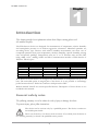
This chapter provides basic information about device. Before starting please read
this manual carefully.
The Web Sensor devices are designed for measurement of temperature, relative humidity
and atmospheric pressure in air without aggressive substances. Measured quantities are
according device type. Devices with relative humidity measurement can show one of
computed quantities: dew point temperature, absolute humidity, specific humidity, mixing
ratio and specific enthalpy. Temperature units are °C or °F. Pressure units are hPa, PSI,
inHg, mBar, oz/in2, mmHg, inH2O and kPa. Communication interface of Web Sensors is
Ethernet. Device types:
Type
T0510
T3510
T7510
T2514
T3511(P)
T4511
T7511
Temperature
Relative humidity
Pressure
Computed quantity
Web Sensor Tx5xxP devices are designed for measurement in compressed air up to 25
bars. The removable probe is integral part of the device. It is not possible to interchange
probe between devices. Probe has connector with protection IP67.
Models marked TxxxxZ are custom-specified devices. Description of these devices is not
included in this manual.
General safety rules
The following summary is used to reduce the risk of injury or damage the device.
To prevent injury, please follow instructions.
The device can be services only by a qualified person. The device contains no
serviceable parts inside.
Don’t use the device, if it doesn’t work correctly. If you think, that the device is
not working correctly, let check it by qualified service person.
4
IE-SNC-Tx5xx-25
It’s forbidden to use the device without the cover. Inside the device can be a dangerous
voltage and may be risk of electric shock.
Use only the appropriate power supply adapter according to manufacturer specifications
and approved according to relevant standards. Make sure, that the adapter does not have
damaged cables or covers.
Connect the device only to network parts approved according to relevant standards.
Connect and disconnect the device properly. Don’t connect or disconnect Ethernet cable
or probes, if the device is powered.
The device may be installed only in prescribed areas. Never expose the device to higher or
lower temperatures than is allowed. The device has not improved resistance to moisture.
Protect it from dripping or splashing water and do not use at areas with condensation.
Devices are not designed for locations with chemically aggressive environment.
Temperature and humidity sensors must not be exposed to direct contact with water or
other liquids. It is not allowed to remove the sensor cover to avoid any mechanical damage
of the sensors.
Before you removing probe of the Web Sensor Tx5xxP, make sure that pressure in a
pressure chamber and ambient pressure are equal.
Don’t use device in explosive environments.
Don’t stress the device mechanically.
Device description and important notices
This chapter contains informations about basic features. Also there are
important notices concerning to functional safety.
Measured values can be displayed on LCD display or can be read using an Ethernet
connection. The following formats are supported:
Web pages with user changeable look and XML files
Modbus TCP protocol
SNMPv1 protocol
SOAP protocol
The device can also be used to check measured values and if the limit is exceeded, device
sends warning messages. Possible ways to sending warning messages:
Sending e-mails up to 3 e-mail addresses
Sending SNMP traps up to 3 configurable IP addresses
Displaying the alarm status on web page
Sending messages to Syslog server
The device setup can be made by the TSensor software or web interface. TSensor software
can be free downloaded from the manufacturer’s website. Also you will find there latest
5
IE-SNC-Tx5xx-25
firmware for your device. Do not upload to your device firmware which is not designed for
it. Unsupported firmware can damage your device.
Device does not support powering over Ethernet cable (PoE). PoE splitter must be used.
Compatible PoE splitter can be purchased as optional accessories. Splitter must have 12V
output with approximately 1W.
Reliability of warning messages delivering (e-mail, trap, syslog), depends on
actual availability of necessary network services. The device should not be used
for critical applications, where malfunction could cause to injury or loss of
human life. For highly reliable systems, redundancy is essential. For more
information please see standard IEC 61508.
Never connect the device directly to the Internet. If it is necessary connect the
device to the Internet, properly configured firewall must be used. Firewall can
be partially replaced by the NAT.
6
IE-SNC-Tx5xx-25
2
Chapter
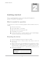
Getting started
Here you can find informations necessary to put newly purchased equipment to
operation. This procedure is only informative.
What is needed for operation
To install the unit you need to the following equipment. Before installation check if it’s
available.
Web Sensor Tx5xx device
power supply adapter 9 - 30V/200mA
RJ45 LAN connection with appropriate cable
free IP address in your network
for Web Sensor T4511 is required temperature probe Pt1000/3850ppm,
connected by shielded cable with maximum length 10m
Mounting the device
check if the equipments from previous chapter are available
install the latest version of TSensor software. This software is used to all
device settings.
TSensor software can be free downloaded from the manufacturer’s website.
Software can be also supplied on CD. Device configuration can be made
using web interface. For web configuration is not TSesnor software necessary.
contact your network administrator to obtain following informations for the
connection to the network:
IP address:
Default gateway:
DNS serer IP:
Subnet mask:
_____._____._____._____
_____._____._____._____
_____._____._____._____
_____._____._____._____
7
IE-SNC-Tx5xx-25
check if there is no IP address conflict when you connect the device into
network for the first time. The device has from factory set the IP address to
192.168.1.213. This address must be changed according to informations from
the previous point. When you installing several new devices, connect them to
the network one after another.
connect probe Pt1000 to Web Sensor T4511
connect the Ethernet connector
connect the power adapter 9 - 30V (e.g. 12V/200mA)
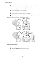
LEDs on LAN connector should blink after connecting the power and LCD
start showing measured values.
Web Sensor T0510, T3510, T7510, T2514, T3511(P), T7511:
Web Sensor T4511:
Device settings
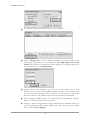
run configuration software TSensor on your PC
switch to an Ethernet communication interface
press button Find device...
8
IE-SNC-Tx5xx-25
the window shows all available devices on your network
click to Change IP to set new address according to network administrator
instructions. If your device is not listed, then click Help! My device wasn’t
found! Then follow the instructions. MAC address is on product label. The
device is factory set to IP 192.168.1.213.
gateway may not be entered if you want to use the device only in local
network. If you set the same IP address which is already used, the device will
not work correctly and there will be collisions on the network. If the device
detects a collision of IP address then reboot is performed automatically.
after changing IP address device is restarted and new IP address is assigned.
Restart of the device takes about 10 seconds.
connect to device using TSensor software and check the measured values. Set
the other parameters (alarm limits, SMTP server, etc.). Settings are saved after
click on button Save changes.
9
IE-SNC-Tx5xx-25
Checking functions
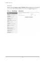
The last step is to check measured values on the device website. In the address bar of the
web browser, enter the device IP address. If the default IP address was not changed, then
insert http://192.168.1.213.
Displayed web page lists actual measured values. If the web pages are disabled, you can see
text Access denied. In the case of measurement error a text Error is shown instead value.
10
IE-SNC-Tx5xx-25
3
Chapter
Device setup
This chapter describes basic device configuration. There is a description of
settings using web interface.
Setup using web interface
Device can be setup using web interface or TSensor software. Web interface can be
managed by the web browser. Main page will be shown when you insert device address
into address bar of your web browser. There you find actual measured values. Page with
history graphs is shown when you click to tile with actual values. Access to device setup is
possible via tile Settings.
11
IE-SNC-Tx5xx-25
General
Device name can be changed using item Device name. Measured values are stored into
memory according History storage interval field. After changing of this interval all
history values will be cleared. Changes must be confirmed by Apply settings button.
12
IE-SNC-Tx5xx-25
Network
Network parameters can be obtain automatically from DHCP server using option Obtain
an IP address automatically. Static IP address is configurable via field IP address. It is
not necessary setup Default gateway while you use device inside one subnet only. DNS
server IP is required to set for proper function of DNS. Option Standard subnet mask
sets network mask automatically according A, B or C network class. Subnet mask field
must be set manually, when network with non standard range is used. Periodic restart
interval enables to restart device after selected time since device start.
13
IE-SNC-Tx5xx-25
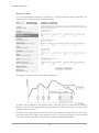
Alarm limits
For each measurement channel is possible to set upper and lower limits, time-delay for
alarm activation and hysteresis for alarm clearing.
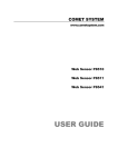
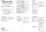
Example of setting the limit to the upper alarm limit:
In Point 1 the temperature exceeded the limit. From this time, the time-delay is counting.
Because at point 2 the temperature dropped below the limit value before the time delay
expired, alarm was not set.
In Point 3 the temperature has risen over limit again. During the time-delay the value does
not drop below the set limit, and therefore was in Point 4 caused alarm. At this moment
were sent e-mails, traps and set alarm flag on website, SNMP and Modbus.
14
IE-SNC-Tx5xx-25
The alarm lasted up to Point 5, when the temperature dropped below the set hysteresis
(temperature limit – hysteresis). At this moment was active alarm cleared and e-mail sent.
When alarm occurs, alarm messages will be sent. In case of power failure or device reset
(e.g. changing the configuration) will new alarm state evaluated and new alarm messages
will be sent.
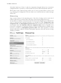
Measuring
Page contains settings of the measuring part of the device. Settings can be saved only if
jumper inside device is closed. Fields in this page are shown according device type.
It is possible set visibility of measured values on device LCD. Display can be switched off.
Units of measured and computed quantities are selectable by fields Temperature unit,
Computed value and Atmospheric pressure unit. Devices without atmospheric pressure
measurement have field Pressure value for computed values. Here is required to set
pressure for calculation of computed quantities. Pressure compensation for altitude above
sea-level is possible via Atmospheric pressure offset. This offset depends on current
altitude. This value is added to measured atmospheric pressure, final value must be in range
300hPa to 1350hPa.
15
IE-SNC-Tx5xx-25
SOAP protocol
SOAP protocol can be enabled by option SOAP protocol enabled. Destination SOAP
server can be set via SOAP server address. For setup of server port can be used option
SOAP server port. Device sends SOAP message according selected Sending interval.
Option Send SOAP message when alarm occurs sends message when an alarm on
channel occurs or alarm is cleared. These SOAP messages are sent asynchronously to
selected interval.
16
IE-SNC-Tx5xx-25
Email
Email sending enabled option allows email features. It is necessary set address of the
SMTP server into SMTP server address field. Domain name for SMTP server can be
used. Default port of the SMTP server can be changed using item SMTP server port.
SMTP authentication can be enabled using SMTP authentication option. When
authentication is enabled Username and Password must be set.
For successfully email sending it is necessary insert Email sender address. This address is
usually same as username of the SMTP authentication. Into fields Recipient 1 to
Recipient 3 it is possible set address of email recipients. Option Short email enable
sending emails in short format. This format is usable when you need to forward emails into
SMS messages.
When option Alarm email repeat sending interval is enabled and there is active alarm on
channel, then emails with actual values are sent repeatedly. Info email sending interval
option enables sending emails at selected time interval. CSV history file can be sent
together with the repeat/info emails. This feature can be enabled by Alarm and Info
emails attachment option.
It is possible to test email function using button Apply and test. This button save a new
settings and send a testing email immediately.
17
IE-SNC-Tx5xx-25
Modbus a Syslog protocols
ModbusTCP and Syslog protocol settings are configurable via menu Protocols. Modbus
server is enabled by default. Deactivation is possible via Modbus server enabled option.
Modbus port can be changed via Modbus port field. Syslog protocol can be enabled using
item Syslog enabled. Syslog messages are sent to IP address of the Syslog server - field
Syslog server IP address.
18
IE-SNC-Tx5xx-25
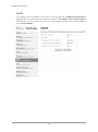
SNMP
For reading values via SNMP it is necessary to know password - SNMP read community.
SNMP Trap can be delivered up to three IP address - IP address of the Trap recipient.
SNMP Traps are sent at alarm or error state on the channel. Trap feature can be enabled by
option Trap enabled.
19
IE-SNC-Tx5xx-25
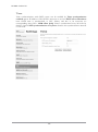
Time
Time synchronization with SNTP server can be enabled by Time synchronization
enabled option. IP address of the SNTP is necessary to set into SNTP server IP address
item. SNTP time is synchronized at UTC format, and due to be necessary set
corresponding time offset - GSM offset [min]. Time is synchronized every 24 hours by
default. Option NTP synchronization every hour decrease this synchronization interval
to one hour.
20
IE-SNC-Tx5xx-25
WWW and security
Security features can be enabled by the Security enabled option. When security is enabled
it is necessary to set administrator password. This password will be required for device
settings. When secured access is required even to actual values reading it is possible to
enable User account only for viewing enabled. Port of the www server can be changed
from the default value 80 using filed WWW port. Web pages with actual values are
refreshed according to Web refresh interval field.
Setup using TSensor software
TSensor software is an alternative to web configuration. Some less important parameters
are configurable only by the TSensor software. TSesnor software allows user adjustment of
measured values.
Parameter MTU size can reduce size of the Ethernet frame. Lowering of this size can
solve some communication problems mainly with Cisco network infrastructure.
21
IE-SNC-Tx5xx-25
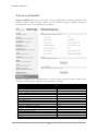
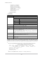
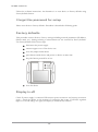
Factory defaults
Factory defaults field set the device into factory configuration. Network parameters (IP
address, Subnet mask, Gateway, DNS) are left without changes. Settings relating to
measurement are not restored by factory defaults.
Network parameters are changed while you close jumper and push button inside device
during connecting power supply. Factory parameters settings:
Parameter
Default value
SMTP server address
SMTP server port
Alarm email repeat sending interval
Info email repeat sending interval
Alarm and Into emails attachment
E-mail recipients addresses
E-mail sender
SMTP authentication
SMTP user/SMTP password
E-mail sending enabled
IP addresses SNMP traps recipients
Password for SNMP reading
Sending SNMP Trap
Website refresh interval [sec]
Website enabled
Website port
Security
example.com
25
off
off
off
cleared
sensor@IP
off
cleared
off
0.0.0.0
public
off
10
yes
80
off
22
IE-SNC-Tx5xx-25
Administrator password
User password
Modbus port
Modbus server enabled
History storage interval [sec]
SOAP server port
SOAP server address
SOAP sending interval [sec]
SOAP message when alarm occurs
SOAP protocol enabled
Syslog server IP address
Syslog protocol enabled
SNTP server IP address
GMT offset [min]
NTP synchronization every hour
SNTP synchronization enabled
MTU
Periodic restart interval
Demo mode
Temperature
High limit
Low limit
Hysteresis
Time delay [sec]
Relative humidity
High limit
Low limit
Hysteresis
Time delay [sec]
Computed quantity
High limit
Low limit
Hysteresis
Time delay [sec]
Atmospheric pressure
High limit
Low limit
Hysteresis
Time delay [sec]
Device name
23
cleared
cleared
502
yes
60
80
cleared
60
yes
off
0.0.0.0
off
217.31.205.226
0
off
off
1400
off
off
50
0
1
30
80
20
1
30
50
0
1
30
1000
700
12
30
Web Sensor
IE-SNC-Tx5xx-25
4
Chapter
Communication protocols
Short introduction to communication protocols of the device. To use some
communication protocols is necessary software, which can use the protocol. This
software is not included. For detailed description of protocols and application
notes please contact your distributor.
Website
The device supports displaying of measured values, history graphs and configuration using
web browser. History graphs are based on HTML5 canvas. Web browser must support this
feature for proper function of graphs. Firefox, Opera, Chrome or Internet Explorer 9 can
be used. If the device has IP address 192.168.1.213 type into your browser
http://192.168.1.213. Using TSensor software or web interface can be set automatic
webpages refresh in interval. The default value is 10sec. Actual measured values can be
obtained using XML file values.xml.
Values from history can be exported in CSV format. History storage interval can be set
using TSensor software or web interface. History is erased after every reboot of the device.
Reboot of the device is performed when the power supply is disconnected and also after
configuration change.
The device allows you to customize the design of web pages. For detailed informations
please contact your distributor.
SMTP – sending e-mails
When measured values are over the set limits, the device allows send e-mail to a maximum
of 3 addresses. E-mail is send when alarm condition on the channel is cleared or a
measuring error occurs. It is possible to set repeat interval for email sending. For correct
sending of e-mails it is necessary to set address of SMTP server. Domain address can be
used as SMTP server address too. For proper function of DNS is required to set DNS
server IP address. SMTP authentication is supported but SSL/STARTTLS not. Standard
SMTP port 25 is used by default. SMTP port can be changed. Contact your network
administrator to obtain configuration parameters of your SMTP server. E-mail sent by the
device can not be answered.
24
IE-SNC-Tx5xx-25
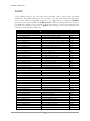
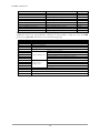
SNMP
Using SNMP protocol you can read actual measured values, alarm status and alarm
parameters. Via SNMP protocol is also possible to get last 1000 measured values from
history table. Writing via SNMP protocol is not supported. It is supported SNMPv1
protocol version only. SNMP used UDP port 161. OID keys description can be found in
the MIB table, which can be obtained from device website or from your distributor. The
password for reading is factory set to public. The changes can be made using TSensor
software or web interface. OID keys:
OID
.1.3.6.1.4.1.22626.1.2.1
.1.3.6.1.4.1.22626.1.2.1.1
.1.3.6.1.4.1.22626.1.2.1.2
.1.3.6.1.4.1.22626.1.2.1.3
.1.3.6.1.4.1.22626.1.2.1.4
.1.3.6.1.4.1.22626.1.2.1.5
.1.3.6.1.4.1.22626.1.2.1.6
.1.3.6.1.4.1.22626.1.2.1.7
.1.3.6.1.4.1.22626.1.2.1.8
.1.3.6.1.4.1.22626.1.2.1.9
.1.3.6.1.4.1.22626.1.2.1.10
.1.3.6.1.4.1.22626.1.2.1.11
.1.3.6.1.4.1.22626.1.2.1.12
.1.3.6.1.4.1.22626.1.2.1.13
.1.3.6.1.4.1.22626.1.2.1.14
.1.3.6.1.4.1.22626.1.2.1.15
.1.3.6.1.4.1.22626.1.2.1.16
.1.3.6.1.4.1.22626.1.2.1.17
.1.3.6.1.4.1.22626.1.2.1.18
.1.3.6.1.4.1.22626.1.2.1.19
.1.3.6.1.4.1.22626.1.2.1.20
.1.3.6.1.4.1.22626.1.2.2
.1.3.6.1.4.1.22626.1.2.2.1
.1.3.6.1.4.1.22626.1.2.2.2
.1.3.6.1.4.1.22626.1.2.2.3
.1.3.6.1.4.1.22626.1.2.3
.1.3.6.1.4.1.22626.1.2.3.1
.1.3.6.1.4.1.22626.1.2.3.2
.1.3.6.1.4.1.22626.1.2.3.3
.1.3.6.1.4.1.22626.1.2.3.4
.1.3.6.1.4.1.22626.1.2.3.5
.1.3.6.1.4.1.22626.1.2.3.6
.1.3.6.1.4.1.22626.1.2.3.7
.1.3.6.1.4.1.22626.1.2.3.8
.1.3.6.1.4.1.22626.1.2.4
.1.3.6.1.4.1.22626.1.2.4.1
.1.3.6.1.4.1.22626.1.2.4.2
.1.3.6.1.4.1.22626.1.2.4.3
.1.3.6.1.4.1.22626.1.2.4.4
.1.3.6.1.4.1.22626.1.2.4.5
.1.3.6.1.4.1.22626.1.2.4.6
.1.3.6.1.4.1.22626.1.2.4.7
.1.3.6.1.4.1.22626.1.2.4.8
.1.3.6.1.4.1.22626.1.2.4.9
.1.3.6.1.4.1.22626.1.2.4.10
Description
Type
Actual measured temperature
Actual measured relative humidity
Actual measured computed quantity
Actual measured atmospheric pressure
Temperature alarm state ("none", "high", "low")
Relative humidity alarm state
Computed quantity alarm state
Atmospheric pressure alarm state
Temperature unit
Relative humidity unit
Computed quantity unit
Atmospheric pressure unit
Min. temperature memory
Min. relative humidity memory
Min. computed value memory
Min. atmospheric pressure memory
Max. temperature memory
Max. relative humidity memory
Max. computed value memory
Max. atmospheric pressure memory
String
String
String
String
String
String
String
String
String
String
String
String
String
String
String
String
String
String
String
String
Device name
Device serial number
Device type
String
String
String
Actual measured temperature
Actual measured relative humidity
Actual measured computed quantity
Actual measured atmospheric pressure
Temperature alarm (0–none, 1–high, 2–low)
Relative humidity alarm state
Computed quantity alarm state
Atmospheric pressure alarm state
Int*10
Int*10
Int*10
Int*X
Integer
Integer
Integer
Integer
Temperature low limit
Temperature high limit
Relative humidity low limit
Relative humidity high limit
Computed quantity low limit
Computed quantity high limit
Temperature time-delay
Relative humidity time-delay
Computed quantity time-delay
Temperature hysteresis
Int*10
Int*10
Int*10
Int*10
Int*10
Int*10
Integer
Integer
Integer
Int*10
25
IE-SNC-Tx5xx-25
.1.3.6.1.4.1.22626.1.2.4.11
.1.3.6.1.4.1.22626.1.2.4.12
.1.3.6.1.4.1.22626.1.2.4.13
.1.3.6.1.4.1.22626.1.2.4.14
.1.3.6.1.4.1.22626.1.2.4.15
.1.3.6.1.4.1.22626.1.2.4.16
.1.3.6.1.4.1.22626.1.5.5.1.0
.1.3.6.1.4.1.22626.1.5.6.1.1.1.nr
.1.3.6.1.4.1.22626.1.5.6.1.1.2.nr
.1.3.6.1.4.1.22626.1.5.6.1.1.3.nr
.1.3.6.1.4.1.22626.1.5.6.1.1.4.nr
Relative humidity hysteresis
Computed quantity hysteresis
Atmospheric pressure low limit
Atmospheric pressure high limit
Atmospheric pressure time-delay
Atmospheric pressure hysteresis
SNMP Trap
Temperature history values
Relative humidity history values
Computed quantity history values
Atmospheric pressure history values
Int*10
Int*10
Int*X
Int*X
Integer
Int*X
String
Int*10
Int*10
Int*10
Int*X
When alarm occurred a warning messages (trap) can be sent to selected IP addresses.
Addresses can be set using TSensor software or web interface. Traps are sent via UDP
protocol on port 162. The device can send following traps:
Trap
Description
0/0
1/0
6/0
6/1
6/2
6/3
6/4
6/5
6/6
6/7
6/8
6/9
6/10
6/11 – 6/14
6/21 – 6/24
6/31 – 6/34
6/41 – 6/44
Reset of the device
Settings was changed
Testing Trap
NTP synchronization error
SMTP server login error
SMTP authentication error
E-mail sending error Some error occurred during SMTP communication
TCP connection to server cannot be opened
DNS error
SOAP file not found inside web memory
DNS error or Host error
SOAP message
sending error
TCP connection to server cannot be opened
Wrong response code from the SOAP server
Upper alarm on channel
Lower alarm on channel
Clearing alarm on channel
Measuring error
26
IE-SNC-Tx5xx-25
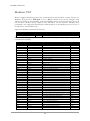
Modbus TCP
Device supports Modbus protocol for communication with SCADA systems. Device use
Modbus TCP protocol. TCP port is set to 502 by default. Port can be changed using
TSensor software or web interface. Only two Modbus clients can be connected to device at
one moment. Modbus device address (Unit Identifier) can be arbitrary. Modbus write
command is not supported. Specification and description of the Modbus protocol is free to
download on: www.modbus.org.
Supported Modbus commands (functions):
Command
Code
Description
Read Holding Register (s)
0x03
Read 16b register(s)
Modbus device registers. Address could be by 1 higher, depending on type used
communication library:
Address [DEC]
Address [HEX]
Value
Type
49
50
51
52
53
54
55
56
57
4149
4150
4151
20481
20482
20483
20484
20485
20486
20487
20488
20489
20490
20491
20492
20493
20494
20495
20496
20497
20498
20499
20500
20501
20502
20503
20504
20505
20506
0x0031
0x0032
0x0033
0x0034
0x0035
0x0036
0x0037
0x0038
0x0039
0x1035
0x1036
0x1007
0x5001
0x5002
0x5003
0x5004
0x5005
0x5006
0x5007
0x5008
0x5009
0x500A
0x500B
0x500C
0x500D
0x500E
0x500F
0x5010
0x5011
0x5012
0x5013
0x5014
0x5015
0x5016
0x5017
0x5018
0x5019
0x501A
Measured temperature
Measured relative humidity
Measured computed quantity
Measured atmospheric pressure
Dew point temperature
Absolute humidity
Specific humidity
Mixing ration
Specific enthalpy
Serial number high
Serial number low
Device type
Temperature low limit
Temperature high limit
Relative humidity low limit
Relative humidity high limit
Computed quantity low limit
Computed quantity high limit
Temperature hysteresis
Temperature time-delay
Relative humidity hysteresis
Relative humidity time-delay
Computed quantity hysteresis
Computed quantity time-delay
Temperature alarm state
Relative humidity alarm state
Computed quantity alarm state
Atmospheric pressure low limit
Atmospheric pressure high limit
Atmospheric pressure hysteresis
Atmospheric pressure alarm state
Atmospheric pressure time-delay
Min. temperature memory
Max. temperature memory
Min. relative humidity memory
Max. relative humidity memory
Min. computed value memory
Max. computed value memory
Int*10
Int*10
Int*10
Int*X
Int*10
Int*10
Int*10
Int*10
Int*10
BCD
BCD
HEX
Int*10
Int*10
Int*10
Int*10
Int*10
Int*10
Int*10
DEC
Int*10
DEC
Int*10
DEC
String
String
String
Int*X
Int*X
Int*X
String
DEC
Int*10
Int*10
Int*10
Int*10
Int*10
Int*10
27
IE-SNC-Tx5xx-25
20507
20508
0x501B
0x501C
Min. atmospheric pressure memory
Max. atmospheric pressure memory
Int*X
Int*X
Type:
DEC
register is in range 0 – 4500 (16bit)
BCD
register is in BCD format (16bit)
HEX
number in HEX format (16bit)
String
two characters in one 16bit register:
Int*10
no
– no alarm
hi
– value is lower than set limit
lo
– value is higher than set limit
register is in format integer*10 – 16 bits:
(125=12.5°C; error = 9999 or -9999)
Int*X
register format depends on value type (error = -9999):
hPa
– integer*10 (9760 = 976.0hPa)
PSI
– integer*1000 (14156 = 14.156PSI)
inHg
– integer*100 (2882 = 28.82inHg)
mBar – integer*10 (9761 = 976.1mBar)
oz/in2 – integer*10 (2265 = 226.5oz/in2)
mmHg – integer*10 (7321 = 732.1mmHg)
inH2O – integer*10 (3919 = 391.9inH2O)
kPa
– integer*100 (9761 = 97.61kPa)
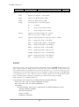
SOAP
The device allows you to send currently measured values via SOAP v1.1 protocol. The
device sends values in XML format to the web server. The advantage of this protocol is
that communication is initialized by the device side. Due to it is not necessary use port
forwarding. If the SOAP message can not be delivered, warning message via SNMP Trap
or Syslog protocol is sent. The file with the XSD schema can be downloaded from:
http://cometsystem.cz/schemas/soapTx5xx_v2.xsd. SOAP message example:
<?xml version="1.0" encoding="utf-8"?>
<soap:Envelope xmlns:soap="http://schemas.xmlsoap.org/soap/envelope/"
xmlns:xsi="http://www.w3.org/2001/XMLSchema-instance"
xmlns:xsd="http://www.w3.org/2001/XMLSchema">
<soap:Body>
<InsertTx5xxSample xmlns="http://cometsystem.cz/schemas/soapTx5xx_v2.xsd">
<passKey>13960932</passKey>
<device>4145</device>
<temp>1.4</temp>
<relHum>91.9</relHum>
28
IE-SNC-Tx5xx-25
<compQuant>0.3</compQuant>
<pressure>-9999</pressure>
<alarms>hi,no,no,no</alarms>
<compType>Dew point</compType>
<tempU>C</tempU>
<pressureU>n/a</pressureU>
<timer>60</timer>
</InsertTx5xxSample>
</soap:Body>
</soap:Envelope>
Element
Description
<passKey>
<device>
Contains the device serial number (an eight digit number).
Device type identification number (code):
Device
Code[DEC]
T3511
4107
T4511
4106
T7511
4129
T2514
4124
T0510
4144
T3510
4145
T7510
4146
Contains the value of temperature (a decimal part of number is separated by a dot).
Error on channel is signaled by 9999 or -9999.
Contains the value of relative humidity. Error value: 9999 or -9999.
Contains the value of computed quantity. Error value: 9999 or -9999.
Contains the value of atmospheric pressure. Error value: -9999.
State of alarm on temperature, relative humidity, computed quantity and pressure
channel. Format: tm,rh,cq,pr where:
tm – temperature alarm, rh – relative humidity alarm, cq – computed quantity
alarm, pr – atmospheric pressure alarm
and alarm values: no – no alarm or value is not supported, hi – high alarm, lo – low
alarm.
Computed quantity type: Absolute humidity, Specific humidity, Mixing
proportion, Specific enthalpy, Dew point or n/a.
Temperature and dew point unit. Values: C – temperature in °C, F – temperature in
°F.
Atmospheric pressure unit. Values: hPa, PSI, inHg, mBar, oz/in^2, mmHg,
inH2O and kPa.
SOAP sending interval [sec].
<temp>
<relHum>
<compQuant>
<pressure>
<alarms>
<compType>
<tempU>
<pressureU>
<timer>
Example of the web service for incoming SOAP messages from Web Sensor Tx5xx.
Example uses Apache (2.2.10) web server and PHP (5.2.6). It is required to install and
enable SOAP extension for PHP. This example store incoming messages to the hard drive:
<?
function InsertTx5xxSample($passKey,$device,$temp,$relHum,$compQuant,$pressure,
$alarms,$compType,$tempU,$pressureU,$timer) {
$data = "Time: ".StrFTime("%y/%m/%d %H:%M:%S", Time()).", Temp: ".$temp.
", RH: ".$relHum.", CQ: ".$compQuant. ", Pressure: ".$pressure."\n";
$file_write = FOpen("soap.log", "a");
FWrite($file_write, $data);
FClose($file_write);
}
$server = new SoapServer(null, array('uri' => "http://test-uri/"));
29
IE-SNC-Tx5xx-25
$server->addFunction('InsertTx5xxSample');
$server->handle();
?>
Syslog
The device allows sending text message to selected Syslog server. Events are send using
UDP protocol on port 514. Syslog protocol implantation is according to RFC5424 and
RFC5426. Events when Syslog messages are send:
Text
Event
Sensor - fw 1-5-5.x
Reset of the device
Settings changed
Settings was changed
NTP synchronization error
NTP synchronization error
Testing message
Test Syslog message
Email login error
E-mail sending error
Email auth error
Email some error
Email socket error
Email dns error
SOAP file not found
SOAP message sending error
SOAP host error
SOAP sock error
SOAP delivery error
SOAP dns error
Text XXXX is set according channel type: Temperature, Relative humidity, Specific humidity, Mixing
proportion, Specific enthalpy, Atmospheric pressure.
High alarm XXXX
Upper alarm on channel
Low alarm XXXX
Lower alarm on channel
Clearing XXXX alarm
Clearing alarm on channel
Error XXXX
Measuring error
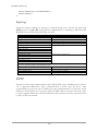
SNTP
The device allows time synchronization with NTP (SNTP) server. SNMP protocol version
3.0 is supported (RFC1305). Time synchronization is made every 24 hours. Time
synchronization every hour can be enabled. For time synchronization it is necessary set IP
address to the SNTP server. It is also possible set GMT offset for correct time zone. Time
is used in graphs and history CSV files. Maximum jitter between two time synchronization
is 90sec at 24 hours interval.
30
IE-SNC-Tx5xx-25
5
Chapter
Troubleshooting
The chapter describes the common problems with devices Web Sensor Tx5xx
and methods how to fix these problems. Please read this chapter before you will
call technical support.
I forgot the device IP address
IP address is factory set to 192.168.1.213. If you had changed it and forgot new IP address,
run the TSensor software and press Find device... In the window are displayed all
available devices.
I can not connect to the device
In search window is only IP and MAC address displayed
Other details are marked N/A. This problem occurs if IP address of the device is set to
another network.
Select the window Find device in TSensor software and press Change IP address.
Follow the software instructions. To assign IP address automatically using DHCP server,
set the device IP address to 0.0.0.0.
Device IP address is not displayed in window Find device
In TSensor software menu press Help! My device was not found! in window Find
device. Follow the software instructions. MAC address of the device can be found on
product label.
The device is not found even after manually setting MAC
address
This problem occurs especially in cases when the IP address of the device belongs to
another network and also Subnet mask or Gateway are incorrect.
In this case is DHCP server in the network necessary. In TSensor software menu press
Help! My device was not found! in window Find device. As new IP address set 0.0.0.0.
31
IE-SNC-Tx5xx-25
Follow the software instructions. An alternative is to reset device to factory defaults using
factory-defaults button.
I forgot the password for setup
Please reset device to factory defaults. Procedure is described at following point.
Factory defaults
This procedure restore device to factory settings including network parameters (IP address,
Subnet mask, etc.). Settings relating to measurement are not restored by factory defaults.
For factory-defaults follow these steps:
disconnect the power supply
unscrew upper cover of the device case
close the jumper inside device
press button inside device and power on device at same time
keep the button pressed for 10 sec
close the device
Display is off
Check if power supply is connected. Disconnect power connector and connect connector
again – watch the display at the moment of connecting the power. If all LCD segments
light for 1 second and go out again, the display is turned off by software.
32
IE-SNC-Tx5xx-25
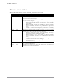
Device error states
Device still make self-tests. If error occurred, LCD shows error codes:
Error
LCD display
Description
Error 0
Err0
Error 1
Err1
Error 2
Err2
Error 3
Err3
Error 4
Err4
Internal memory CRC error. In this state device doesn't work. This is a
critical error, contact the distributor.
Measured or computed quantity is over the upper limit. Error code 9999.
This state appears in case of:
- Measured temperature is higher than approximately +600°C (i.e.
high non-measurable resistance of temperature sensor, probably
open circuit)
- Relative humidity is higher than 100%RH (i.e. damaged humidity
sensor or humidity calculation is not possible due to temperature
error)
- Unable to calculate computed quantity (temperature or humidity
measurement error)
Measured or computed quantity is under lower limit or is error in pressure
measuring. Error code -9999. This state appears in case of:
- Measured temperature is lower than approximately -210°C (i.e.
resistance is too small, probably short circuit)
- Relative humidity is lover than 0%RH (i.e. damaged humidity
sensor or humidity calculation is not possible due to temperature
error)
- Measured atmospheric pressure with offset is over range 300hPa to
1350hPa or the pressure sensor is damaged
- Unable to calculate computed quantity (temperature or humidity
measurement error)
Internal A/D converter error. Error code -9999. In this state device doesn't
work. Contact the distributor.
Internal pressure sensor error. Error code -9999. In this state device not
measure pressure. Contact the distributor.
33
IE-SNC-Tx5xx-25
6
Chapter
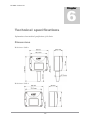
Technical specifications
Informations about technical specifications of the device.
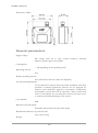
Dimensions
Web Sensor T0510:
Web Sensor T2514:
34
IE-SNC-Tx5xx-25
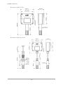
Web Sensor T3510, T7510:
Web Sensor T3511(P), T7511:
35
IE-SNC-Tx5xx-25
Web Sensor T4511:
General parameters
Supply voltage:
DC voltage from 9V to 30V, coaxial connector, 5x2.1mm
diameter, positive pole in the middle
Consumption:
~ 1W depending on the operating mode
Measuring interval:
2sec
Display switching interval:
4sec (when more than two values are displayed)
Not allowed manipulations:
It is not allowed to operate the device under conditions other than
specified in technical parameters. Devices are not designed for
locations with chemically aggressive environment. Temperature
and humidity sensors must not be exposed to direct contact with
water or other liquids. It is not allowed to remove the sensor cover
to avoid any mechanical damage of the sensors.
Case material:
ABS
Material of T3511P probe:
duralumin with the black eloxal surface finish
Mechanical connection of probe T3511P:
G1/2 with O-ring
Weight:
36
IE-SNC-Tx5xx-25
T2514 ~130g
T0510 ~145g
T4511 ~145g
T3510 ~155g
T7510 ~155g
T3511/1m probe ~210g, T3511/2m probe ~250g, T3511/4m
probe ~330g
T3511P/1m probe ~260g, T3511P/2m probe ~300g, T3511P/4m
probe ~380g
T7511/1m probe ~210g, T7511/2m probe ~250g, T7511/4m
probe ~330g
Mounting the device:
With two holes at the bottom of the unit
Communication port:
RJ45 connector, 10Base-T/100Base-TX Ethernet (Auto-Sensing)
Recommended Connector Cable:
for industrial use is recommended Cat5e STP cable, in less
demanding applications can be replaced by Cat5 cable, maximum
cable length 100m
Supported protocols:
TCP/IP, UDP/IP, ARP, ICMP, DHCP, TFTP, DNS
HTTP, SMTP, SNMPv1, ModbusTCP, SNTP, SOAPv1.1, Syslog
Supported SNMP authentication types:
AUTH LOGIN
Supported web browsers:
Internet Explorer 9 and later, Mozilla Firefox 12 and later, Google
Chrome 18 and later, Opera 11 and later
Recommended minimum screen resolution:
1024 x 768
Memory:
1000 values for each channel inside non-backup RAM memory
EMC emission:
EN 55022, Class B
EMC resistance:
EN 61000-4-2, levels 4/8kV, Class A
EN 61000-4-3, intensity of electromagnetic filed 3V/m, Class A
EN 61000-4-4, levels 1/0.5kV, Class A
EN 61000-4-6, intensity of electromagnetic filed 3V/m, Class A
37
IE-SNC-Tx5xx-25
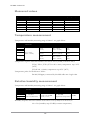
Measured values
Type
T0510
T3510
T7510
T2514
T3511(P)
T4511
T7511
Temperature
Relative humidity
Pressure
Computed quantity
Temperature measurement
Temperature and humidity measuring range is limited - see graph below.
Type
T0510
T3510
T7510
T4511
Operating temperature Accuracy
of electronic
-30 to +80°C
(-22 to +176°F)
T3511(P)
T7511
Range
Resolution
±0.6°C
(±1.1°F)
-30 to +80°C
(-22 to +176°F)
0.1°C
(0.2°F)
±0.2°C
(±0.4°F)
-200 to +600°C
(-225 to +999°F)
0.1°C
(0.2°F)
±0.4°C
(±0.7°F)
-30 to +105°C
(-22 to +221°F)
0.1°C
(0.2°F)
Temperature response time with stainless steel sensor cover (F5200) in air flow 1m/s:
T3510, T3511, T7510, T7511 t90 < 6min, temperature step 20°C
(36°F)
T3511P t90 < 16min, temperature step 20°C (36°F)
Temperature probe for Web Sensor T4511:
Pt1000/3850ppm, connected by shielded cable max. length 10m
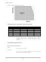
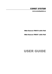
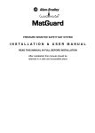
Relative humidity measurement
Temperature and humidity measuring range is limited - see graph below.
Type
T3510
T7510
T3511(P)
T7511
Operating humidity of Accuracy
electronic
0 to 100%RH
without condensation
±2.5%RH
in range 5 to 95%RH
in 23°C (73.4°C)
Range
Resolution
0 to 100%RH
0.1%RH
temperature compensated
Humidity response time with stainless steel sensor cover (F5200) in air flow 1m/s:
t90 < 30s (humidity step 65%RH, constant temperature)
38
IE-SNC-Tx5xx-25
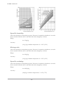
Relative humidity and temperature restrictions:
Atmospheric pressure measurement
Unit
hPa
mBar
PSI
mmHg
inHg
inH2O
±oz/in2
kPa
Range
Accuracy
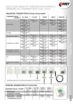
600 to 1100
600 to 1100
8.70 to 15.95
450.0 to 825.1
17.72 to 32.48
240.9 to 441.6
139.2 to 255.3
60.00 to 110.00
T = 23°C
0 ≤ T ≤ 40°C
else
±1.3
±1.3
±0.02
±1.0
±0.04
±0.5
±0.3
±0.13
±1.5
±1.5
±0.02
±1.1
±0.04
±0.6
±0.3
±0.15
±2.0
±2.0
±0.03
±1.5
±0.06
±0.8
±0.5
±0.20
Atmospheric pressure response time:
t90 < 44s (Response time is selectable. More detail you find in
calibration manual, which is included with TSensor software
installation.)
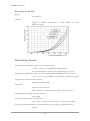
Computed quantities
Dew point temperature
Range:
-60 to +80°C (-20 to 176°F)
Accuracy:
±1.5°C (±2.7°F) at ambient temperature T < 25°C (77°F) and
RH > 30%, for more details see graphs:
39
IE-SNC-Tx5xx-25
Specific humidity
This value depends on atmospheric pressure. Pressure for quantities calculation is stored in
device memory. Default value is 1013hPa and can be changed by software.
Range:
0 to 550g/kg
Accuracy:
±2.1g/kg at ambient temperature T < 35°C (95°F)
Mixing ratio
This value depends on atmospheric pressure. Pressure for quantities calculation is stored in
device memory. Default value is 1013hPa and can be changed by software.
Range:
0 to 995g/kg
Accuracy:
±2.2g/kg at ambient temperature T < 35°C (95°F)
Specific enthalpy
This value depends on atmospheric pressure. Pressure for quantities calculation is stored in
device memory. Default value is 1013hPa and can be changed by software.
Range:
0 to 995kJ/kg
Accuracy:
±4kJ/kg at ambient temperature T < 25°C (77°F)
40
IE-SNC-Tx5xx-25
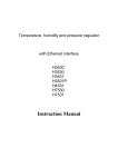
Absolute humidity
Range:
0 to 400g/m3
Accuracy:
±3g/m3 at ambient temperature T < 40°C (104°F), for more
details see graph:
Operating terms
Temperature and humidity range in case with electronic:
-30°C to +80°C, 0 to 100%RH (no condensation)
It is recommended to switch off in temperature over +70°C.
Temperature and humidity range of external probe, cable including (T3511(P), T7511):
-30 to +105°C, 0 to 100%RH (no condensation, limited by graph)
Temperature of Pt1000 probe (T4511):
depends on probe model
Protection:
IP30 case with electronic
IP40 temperature-humidity probe (T3511, T3511P, T7511)
Operating pressure range of probe T3511P:
up to 25bar
Air flow velocity around T3511P probe:
up to 25m/s at pressure of 1bar (1m/s at a pressure of 25bar)
Other environmental conditions (external influences) according to HD 60364-5-51:
normal
41
IE-SNC-Tx5xx-25
Working position T2514, T3511(P), T4511, T7511:
arbitrary
Working position T0510, T3510, T7510:
with sensor cover downwards. When mounting in RACK 19" with
universal holder MP046 (optional accessories) then sensor cover
can be placed horizontally.
End of operation
Disconnect the device and dispose it according to current legislation for
dealing with electronic equipment. Electronic devices must be professionally
destroyed in accordance with EU Directive 2002/96/ES of 27th January 2003.
Technical support and service
Technical support and service is provided by distributor. Contact is included in warranty
certificate.
Preventive maintenance
Make sure the cables are not damaged periodically. We recommend you periodic calibration
for measurement accuracy validation. Recommended calibration interval:
Type
Calibration interval
T0510
T3510
T7510
T2514
T3511(P)
T4511
T7511
2 years
1 year
1 year
1 year
1 year
2 years
1 year
42
IE-SNC-Tx5xx-25
7
Chapter
Optional accessories
This chapter contains list of optional accessories, which can be ordered by extra
cost. Manufacturer recommends using only original accessories.
Temperature probe Pt1000 for Web Sensor T4511
Wide ranges of Pt1000/3850ppm probes are available as optional accessories. Please
contact your local distributor to help you with choice of correct probe according your
application.
Power supply Adapter A1515
Power supply adapter with CEE 7 plug, 100-240V 50-60Hz/12V DC, 0.5A for Web
Sensor devices.
Device case holder for RACK 19" MP046
MP046 is a universal holder for mounting of Web Sensor devices into RACK 19".
Probes holder for RACK 19" MP047
Universal holder for easy mounting probes in RACK 19".
Flow chamber SH-PP for Web Sensor T3511P
Flow chamber for compressed air measurement up to 25 bars. Made from stainless steel
DIN 1.4301, inlet and outlet connection - G1/8, thread for humidity probe connection G1/2.
43
www.cometsystem.cz