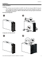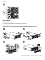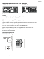
1
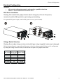
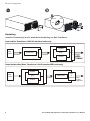
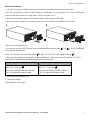
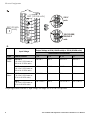
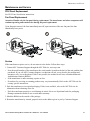
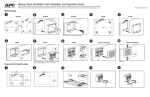
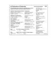
User Manual
English
APC Isolation and Step-Down Transformers
10/20 kVA
990-2807
01//2006
Introduction
Introduction
The APC 10 kVA and 20 kVA isolation transformers are used as filters, isolating the UPS and connected
equipment from any outside utility line fluctuations or interference.
The APC 10 kVA step-down transformers are used to convert a higher output voltage (208-200 V) to a lower
output voltage (120-100 V) which might be more fitting for certain environments or system configurations.
The isolation and step-down transformers can be installed in either tower or rack-mount configurations.
Note: Illustrations in this document may vary from your actual configuration.
Unpacking
Read the Safety Guide before installation.
Inspect the transformer upon receipt. Notify the carrier and dealer if there is damage.
The packaging is recyclable; save it for reuse or dispose of it properly.
Check the package contents:
•
•
•
•
•
Transformer
Four front bezels
Four handles
Rail kit
Literature kit containing:
• Product documentation
•
User Manuals CD
•
Safety information
•
Warranty information
•
Label stickers
•
Rack-mounting brackets
•
Rail-aligning brackets
•
Top cover
•
Mounting stabilizers
•
Hardware
•
Communication cable
Environmental Specifications
This unit is designed for indoor use only. Do not operate the unit where there is excessive dust.
Temperature
32° to 104° F (0° to 40° C)
Humidity
0 to 95% relative humidity, non-condensing
The unit is heavy. Select a location sturdy enough to handle the weight.
220/260 lb
(113/118 kg)
APC Isolation and Step-Down Transformers 10/20 kVA User Manual
3
Introduction
Electrical Specifications
Attention: Adhere to all local and national electrical codes.
Model
Nominal Input
Voltage- Single Phase
Nominal Input
Voltage- Two Phase
APTF10KW01
APTF10KT01
APTF10KJ01
APTF20KW01
200-240, 208,
240 Vac
208, 240 Vac
200 Vac
200-240, 208,
240 Vac
380-415, 480 Vac
480 Vac
400 Vac
380-415, 480 Vac
Input Voltage Range
170-480 Vac
Input Current RatingSingle Phase
48 A
80 A
Input Current RatingTwo Phase
24 A
40 A
Hardwire (6 AWG)
Hardwire (3 AWG)
Input Connection
Line Frequency
Efficiency
45-65 Hz
94%
94%
92 %
96%
Nominal Output
Voltage
220-240, 240, 200,
208, 120, 100 Vac
240, 208, 120 Vac
200, 100 Vac
220-240, 240, 200, 208,
120, 100 Vac
Output Receptacles*
Hardwire (6 AWG)
Hardwire (6 AWG),
PDU: (2) L14-30,
(2) L5-20
Hardwire (6 AWG),
PDU: (2) L14-30,
(2) L5-20
Hardwire (3 AWG)
10 kVA
10 kW
10 kVA
10 kW
10 kVA
10 kW
20 kVA
20 kW
Maximum Output
Power**
* Optional PDU panels are available for 10 kVA units. See www.apc.com for further information.
** Low voltages will decrease the maximum output power and VA.
Handle Installation
Install the four handles, lift the transformer off of the pallet, and move to the mounting location. Note: If rackmounting, install the handles after the rack-mounting and rail-aligning brackets (see Rack Installation).
4
APC Isolation and Step-Down Transformers 10/20 kVA User Manual
Electrical Configuration
Electrical Configuration
Attention:
•
•
All electrical configurations must be performed by a qualified electrician.
Adhere to all local and national electrical codes.
PDU Panel Installation
Warning: The terminal block jumper location must be changed (see Wire the Transformer).
Attention: Install the PDU panel before performing any hardwiring.
For optional PDU panel output, install a PDU panel accessory (not included).
Voltage Switch Selection
Warning: Do not adjust voltage selection switch while input voltage is applied. Load(s) may be damaged.
Before the transformer is connected to utility power, select the voltage required for the specific configuration
by setting the voltage selection switch, located on the rear panel. See graphics that follow.
2
Input Voltage
Utility Voltage Selector Switch Output Voltage
Position
220-240
200-240
220-240
208
208
240/208/120
240
200-240
240/208/120
200
200-240
200/100
380-415
400
220-240
400 (Japan)
480
200/100
480
480
240/208/120
APC Isolation and Step-Down Transformers 10/20 kVA User Manual
5
Electrical Configuration
200-240
480
208
400
Hardwiring
Attention: If mounting in a rack, mount before hardwiring (see Rack Installation).
Input Isolation Transformer (10/20 kVA hardwired units only):
Bypass
Utility
Power
Transformer
Hardwire
Hardwire
UPS
P
D
U
Inverter
Output Isolation/Step-Down Transformer (10 kVA hardwired/PDU units only):
Bypass
Utility
Power
Hardwire
Inverter
6
Transformer
UPS
PDU
or
Hardwire Power
to Load
Equipment
APC Isolation and Step-Down Transformers 10/20 kVA User Manual
Electrical Configuration
Wire the Transformer
1. For input wiring only, install a utility circuit breaker in accordance with local electrical codes.
Note: The circuit breaker values for 10 kVA units are: single phase- 60 A, two phase- 30 A. The circuit breaker
values for the 20 kVA units are: single phase- 100 A, two phase- 50 A.
2. Switch the transformer input circuit breaker, and the utility circuit breaker OFF.
3. Remove the access panel, by removing screws. (See A for 10 kVA unit and B for 20 kVA unit.)
A.
B.
4. Remove circular knockouts.
5. If installing an optional PDU panel, move the terminal block jumper from
block jumper identification
Note: 100/120/200 V units should be wired
-7 to
-8. See C for terminal
-8; and, 220/230/240 V units should be wired
-7.
6. Run wires through the knockout holes to the terminal blocks. Wire to the ground block first. (See C for
terminal block identification and D for terminal block connections.)
Input Connections
Wire to L1, L2/N, and
Output Connections (optional)
.
Wire to the grounding electrode conductor
(GEC) for optional secondary ground.
Wire to 7, 8, 9, 10, and
.
Wire to the grounding electrode conductor
(GEC) for optional secondary ground.
7. Switch the circuit breakers ON.
8. Check line voltages.
9. Reinstall the access panel.
APC Isolation and Step-Down Transformers 10/20 kVA User Manual
7
Electrical Configuration
GEC (10 kVA units)
7
7
8
8
GEC (20 kVA
units)
230 V
units
9
10
7
L1
8
100/120/200/
208/240 V
units
D.
Input Voltage
Output Voltage at 60 A (10 kVA units) or 100 A (20 kVA units)
Terminal Block Connections
Type
Switch Position
7, 10
7, 9
8, 10
8, 7
Single
Phase
200-240 V
(60 A for 10 kVA units or
100 A for 20 kVA units)
200/240 V
208 V
100/120 V
100/120 V
208 V
(60 A for 10 kVA units or
100 A for 20 kVA units)
240 V
208 V
120 V
120 V
400 V
(30 A for 10 kVA units or
50 A for 20 kVA units)
220/240 V
N/A
N/A
N/A
480 V
(30 A for 10 kVA units or
50 A for 20 kVA units)
240 V/200 V*
208 V
120 V/100 V*
120 V/100 V*
Two
Phase
* Japan applications with 400 V input voltage will output 200 V or 100 V as specified.
8
APC Isolation and Step-Down Transformers 10/20 kVA User Manual
Installation
Installation
Tower Installation
Attention:
• The transformer must be installed to the LEFT of the UPS when facing the FRONT of the units.
• If your configuration includes the optional bypass panel, ensure this is installed to the LEFT of
the transformer when facing the FRONT of the units. Refer to the bypass panel documentation
for installation instructions.
Stand-Alone Configuration
Configuration with Smart-UPS RT
APC Isolation and Step-Down Transformers 10/20 kVA User Manual
9
Installation
Rack Installation
Install the Rails in the Rack
For details on rail installation refer to the instructions in the rail kit.
Tower to Rack Conversion
Attention: Due to its weight, the transformer should be installed at the bottom of the rack.
XFMR
10
APC Isolation and Step-Down Transformers 10/20 kVA User Manual
Installation
Connecting Equipment and Power to the Transformer
10 kVA Rear Panel:
20 kVA Rear Panel:
Start-Up
Attention:
•
•
Wiring must be performed by a qualified electrician.
Adhere to all local and national electrical codes.
1. Check that all power is turned OFF.
2. If necessary, replace the PDU panel (see PDU Panel Installation).
3. Select the output voltage by setting the voltage selection switch (see Voltage Switch Selection).
4. Hardwire the transformer (see Hardwiring).
5. For PDU panel configurations only, connect loads to the transformer.
6. Install optional communication cable (see following Optional Communication Cable).
7. Check that the input circuit breaker is turned ON.
8. Turn on all connected equipment.
Optional Communication Cable
8 Pin RJ45, Fault/Warning
1
Identifying Resistor
3.65 K
2
3
4
5
common
Contact 1
6
7
8
APC Isolation and Step-Down Transformers 10/20 kVA User Manual
11
Installation
Communication Cable Signals
Wire Color
Name
Signal
Function
-
For connection
to AP9619
For connection to
AP9340 or AP9350
Polarity
Zone 1 NC* or
Zone 2 NC*
User 1 Negative (-) or
User 2 Negative (-)
-
Green
Common
White with
brown
Contact 1
Fan fail and
thermal
warning
Zone 1 COM**
User 1 Positive (+)
Opens when
event occurs
Brown
Contact 2
Thermal
shutdown
Zone 2 COM**
User 2 Positive (+)
Opens when
event occurs
* Normally closed
** Common
Troubleshooting
PROBLEM AND/OR POSSIBLE CAUSE
SOLUTION
Contact 1 (Fan Fault/Thermal Warning)
A fan may be blocked or running slowly.
• Make sure that the fans are not blocked.
• Reduce the load if possible.
• Contact a service representative immediately.
Note: The contact set is designed to open as a
warning before the unit enters thermal shutdown.
The system may shutdown within one hour if
appropriate action is not taken.
The internal temperature of the unit is above the
normal range.
Contact 2 (Input Circuit Breaker Postion)
The input current rating has been exceeded.
The internal temperature is above the safe operating
range.
12
• Reduce the load and close the breaker.
• If the breaker will not stay closed, contact a service
representative.
Note: If the breaker is open this contact set will be
open.
APC Isolation and Step-Down Transformers 10/20 kVA User Manual
Maintenance and Service
Maintenance and Service
PDU Panel Replacement
See PDU Panel Installation instructions.
Fan Panel Replacement
Attention: Handle only the fan panel during replacement. The transformer and other components will
continue operating and remain active during fan panel replacement.
Upon fan panel removal, the fans immediately turn off; upon insertion of the new fan panel, the fans
immediately have power.
Service
If the transformer requires service, do not return it to the dealer. Follow these steps:
1. Contact APC Customer Support through the APC Web site, www.apc.com.
•
Note the model number of the transformer, the serial number located on the back of the unit, and the date
purchased. If you call APC Customer Support, a technician will ask you to describe the problem and
attempt to solve it over the phone. If this is not possible, the technician will issue a Returned Material
Authorization Number (RMA#).
•
•
If the transformer is under warranty, repairs are free.
Procedures for servicing or returning products may vary internationally. Refer to the APC Web site for
country specific instructions.
2. Pack the transformer in its original packaging. If this is not available, refer to the APC Web site for
information about obtaining a new set.
•
Pack the transformer properly to avoid damage in transit. Never use Styrofoam beads for packaging.
Damage sustained in transit is not covered under warranty.
3. Mark the RMA# on the outside of the package.
4. Return the transformer by insured, prepaid carrier to the address given to you by Customer Support.
APC Isolation and Step-Down Transformers 10/20 kVA User Manual
13
Regulatory, Warranty, and Contact Information
Regulatory, Warranty, and Contact Information
FCC Compliance Notice
This equipment has been tested and found to comply with the limits for a Class A digital device, pursuant to
part 15 of the FCC Rules. These limits are designed to provide reasonable protection against harmful
interference when the equipment is operated in a commercial environment. This equipment generates, uses, and
can radiate radio frequency energy. If it is not installed and used in accordance with the instruction manual, it
may cause harmful interference to radio communications. Operation of this equipment in a residential area is
likely to cause harmful interference in which case users will be required to take whatever measures may be
necessary to correct the interference at their own expense.
Regulatory Approvals
LR63938
N394
geprüfte
Sicherheit
ME 61
Date of Product Declaration
American Power Conversion
Ballybritt Business Park
Gallway, Ireland
73/23/EEC; 89/336EEC; 93/68/EEC
Uninterruptible Power Supply
American Power Conversion
132 Fairgrounds Rd.
West Kingston, RI 02892 USA
APTF10KW01, APTF20KW01
American Power Conversion
1600 Division Rd.
West Warwick, RI 02893 USA
American Power Conversion
Ballybritt Business Park
Galway, Ireland
Galway, Ireland
14
American Power Conversion
Breaffy Rd.
Castelbar
Co Mayo, Ireland
American Power Conversion
40 Catamore Blvd.
East Providence, RI 02914 USA
APC India Pvt, Ltd.
187/3, 188/3, Jigani Industrial Area
Bangaldore, 562106
Kanataka
India
American Power Conversion
Lot 3, Block 14, Phase 3
PEZA, Rosario, Cavite
Philippines
American Power Conversion
2nd Street
PEZA, Cavite Economic Zone
Rosario, Cavite
Philippines
American Power Conversion
Lot 10, Block 16, Phase 4
PEZA, Rosario, Cavite
Philippines
APC Brazil LTDA.
AI.Xingu, 850
Barueri
Alphaville/Sao Paulo
06455-030
Brazil
APC (Suzhou) UPS Co.,Ltd
339 Suhong Zhong Lu
Suzhou Industrial Park
Suzhou Jiangau 2215021
P. R. China
APC Isolation and Step-Down Transformers 10/20 kVA User Manual
Regulatory, Warranty, and Contact Information
Limited Warranty
American Power Conversion (APC) warrants its products to be free from defects in materials and workmanship
for a period of two years from the date of purchase. Its obligation under this warranty is limited to repairing or
replacing, at its own sole option, any such defective products. To obtain service under warranty you must obtain
a Returned Material Authorization (RMA) number from customer support. Products must be returned with
transportation charges prepaid and must be accompanied by a brief description of the problem encountered and
proof of date and place of purchase. This warranty does not apply to equipment that has been damaged by
accident, negligence, or misapplication or has been altered or modified in any way. This warranty applies only
to the original purchaser who must have properly registered the product within 10 days of purchase.
EXCEPT AS PROVIDED HEREIN, AMERICAN POWER CONVERSION MAKES NO WARRANTIES,
EXPRESSED OR IMPLIED, INCLUDING WARRANTIES OF MERCHANTABILITY AND FITNESS FOR
A PARTICULAR PURPOSE. Some states do not permit limitation or exclusion of implied warranties;
therefore, the aforesaid limitation(s) or exclusion(s) may not apply to the purchaser.
EXCEPT AS PROVIDED ABOVE, IN NO EVENT WILL APC BE LIABLE FOR DIRECT, INDIRECT,
SPECIAL, INCIDENTAL, OR CONSEQUENTIAL DAMAGES ARISING OUT OF THE USE OF THIS
PRODUCT, EVEN IF ADVISED OF THE POSSIBILITY OF SUCH DAMAGE. Specifically, APC is not
liable for any costs, such as lost profits or revenue, loss of equipment, loss of use of equipment, loss of
software, loss of data, costs of substitutes, claims by third parties, or otherwise.
Customer Support
In the USA: Refer to the APC Web site, www.apc.com/support.
Worldwide: Refer to the APC Web site, www.apc.com. Select the appropriate country from the country
selection field. Select the Support tab at the top of this web page.
After selecting a country, see www.apc.com/support/contact for e-mail and phone numbers available.
Entire contents copyright 2006 American Power Conversion Corporation. All rights reserved. Reproduction in
whole or in part without permission is prohibited.
APC, the APC logo, Smart-UPS, Symmetra, and PowerChute are registered trademarks of American Power
Conversion Corporation. All other trademarks are the property of their respective owners.
APC Isolation and Step-Down Transformers 10/20 kVA User Manual
15