1
MICROELECTROMECHANICAL SYSTEMS (MEMS)
MEMS
Microelectromechanical Systems, or MEMS, is a technology that uses miniaturised mechanical and electromechanical elements that are
made using the techniques of microfabrication. The physical dimensions of MEMS devices can vary from well below one micron all the
way to several millimetres.
Our MEMS microsensor is a small discrete device that converts a measured mechanical signal, gravity (g) into a voltage signal.
Operation
Applications
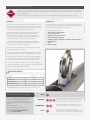
The inclinometer probe is inserted into the inclinometer casing
and lowered to depth, ensuring the probe wheels are correctly
aligned and slotted within the keyways of the casing. The probe
is connected by a graduated cable to the cable reel.
Inclinometer systems are used to measure lateral displacement in
the ground or structure. They are useful for determining the depth,
direction, magnitude and rate of movement.
Displacement readings are taken at regular intervals of 0.5m
within the casing (the gauge length between the probe
wheels). This is measured and controlled by metal markers
crimped around the cable that pass through a notch in the
cable gate, giving an exact position for each reading.
A key fob activates the saving of readings from the MEMS
sensors, which are transmitted to the Field PC from the cable
reel via Bluetooth transmission and saved.
Typical applications include:
• Slope failures and landslides
• Shear and slip zones
• Diaphragm or sheet pile walls
• Monitoring bending in piles
• Verifying design assumptions and finite element analysis
• Embankments
• Dams
• Retaining walls
An initial or ‘base’ set of inclinometer readings are obtained at
each increment within the casing.
The summation of each incremental reading provides a profile
of horizontal displacement of the casing as a function of depth.
When you take all subsequent readings at identical depths the
comparison of successive casing profiles indicates the depth,
direction, magnitude and the rate of change of movement.
You can see the clearest indication of movement by plotting the
change in displacement of the casing against depth using ‘In-Site’
Inclinometer Data Management Package.
Associated products
For details on:
Catalogue code:
EC Casing
C9
Standard Casing
C18
‘In-Site’ Software
C13
Inclinometer Test Probe
C10
View our full product range on www.soilinstruments.com
THE TECHNICAL RATING FOR THIS PRODUCT:
As the correct installation of any monitoring sensor
or system is vital to maximise performance and
accuracy, Soil Instruments makes the following
recommendations, for the skill level of the installation
contractor.
ADDITIONAL SUPPORT
We offer installation and monitoring services
to support this system. For more information
please email : [email protected]
or call : +44 (0) 1825 765044
BASIC
ADVANCED
INTERMEDIATE
BASIC
The installer is trained and experienced in the installation
of this type of instrument or systems, and is ideally a
specialist Instrumentation and Monitoring contractor.
The installer already has previous experience and/or
training in the installation of this instrument or system.
As a minimum the installer has read and fully
comprehends the manual, and if possible has observed
these instruments or systems being installed by others.