1
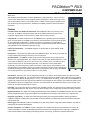
PACMotion™ RX3i
IC695PMM335-AD
GFK-2449E
March 2010
Multi-axis Motion Controller
The PACMotion Multi-axis Motion Controller (PMM335) is a high performance, easy-to-use servo
motion control module that is closely integrated with the PACSystems™ RX3i CPU’s logic solving
and communications functions. This versatile motion controller combines highly integrated motion
and machine logic with the performance, flexibility and scalability required for advanced machine
automation.
Features
Four Servo Axes Plus Additional Virtual Axis - Each PMM335 module can control up to four
servo axes. An additional virtual (time-based) axis and an additional external encoder can be
configured. Eight modules can be included in a single rack for a total of 40 axes.
Faceplate I/O - The built-in faceplate I/O on the PMM335 has four general-purpose 24 volt digital
inputs, two high-speed 24 volt digital inputs with open wire fault detection, and two general-purpose
24 volt configurable inputs/outputs. In addition to simple I/O, Faceplate I/O is configurable for
motion-specific functionality such as Touch Probe inputs, Overtravel Limit switches, Home switches,
and A Quad B Encoder and Marker inputs (Axis 5 only).
Fiber I/O Terminal Block – The PMM335 supports an optional Fiber I/O Terminal Block (FTB),
IC695FTB001.
Performance - The position loop update rate of the PMM335 is 500μs. The velocity loop update rate
is 125μs. Motion path planning is done every 1ms for all five axes.
Synchronization - The PMM335 provides synchronized or delayed start of up to eight axes. For
electronic cam or gear applications, any number of real (motor) or virtual (time-based) axes in a rack
can be used as masters for one or more slave axes on any module in a rack. For electronic cams,
master and slave axes can be rescaled dynamically. A cam slave axis can be phase shifted
dynamically. Two electronic gearing modes are provided, a simple velocity synchronization, and a
velocity/position synchronization. Velocity-synchronized gear slaves can have moves superimposed
dynamically allowing jerk-limited position adjustments. For both gearing and camming, the PMM335
uses a ramping function to synchronize a slave to a moving master.
Cam Profiles - Electronic cams can be created using the built-in cam editor in the Proficy® software or imported via CSV
(comma separated variable) file. The cam editor allows master/slave points to be added in either a table or through graphical
manipulation. Point data can be fitted using 1st, 2nd, 3rd, or 5th degree spline curve fitting. A cam profile can be subdivided into
segments (3 points minimum per segment) with a different curve fit degree for each segment. Up to 2048 cam profiles can be
downloaded and stored on the RX3i CPU at one time. Up to 256 profiles can be selected and stored on each module. Cam
profiles can be replaced dynamically as required.
Interrupts - Up to three interrupts are provided for each PACMotion module. One interrupt can be configured as time based
with configurable update time down to 2ms. Any of the three interrupts can be configured as I/O input event driven interrupts.
Digital Cam Switch - The digital cam switch (programmable limit switch) capability of the PMM335 provides up to four outputs
(tracks) using either regular or high-speed outputs on the faceplate or the FTB. Each track can have up to eight switches.
Diagnostic Logic Block - To assist with commissioning and debug, the Proficy Machine Edition software provides the
capability to program one diagnostic logic block that can be downloaded to the RX3i CPU and executed without altering the
main program logic.
Data Logging -The PMM335 provides the capability to log data during runtime. Using Proficy Machine Edition, this data can
subsequently be uploaded and displayed.
PLCopen Compliance -The PMM335 module is designed to be compliant with the PLCopen specification for motion. All
motion functionality is controlled by specialized functions and function blocks integrated into the CPU logic. Capabilities of
motion function blocks include blending and buffering of blocks, and velocity, acceleration and jerk limited motion.
2
PACMotion RX3i Multi-Axis Motion Controller
GFK-2449E
Specifications
For RX3i environmental specifications, refer to the PACSystems Rx3i System Manual, GFK-2314.
Specification Details
Comments
Motion Path Planning
1ms
Consistent update regardless of the number of axes in the
system
Position Loop Update Rate
500μs
All axes in the RX3i rack are updated simultaneously
Velocity Loop Update Rate
125μs
All axes in the RX3i rack are updated simultaneously
Torque Loop Update Rate
62.5μs
All axes in the RX3i rack are updated simultaneously
Controlled Axes/Module
4
βi, βHVi or αHVi series servos are supported via a fiber optic
interface
Master Axes/Module
1
Can be a virtual time-based or incremental encoder master
Servo Command Interface
Fiber Optic
50Mb/s FANUC Serial Servo Bus (FSSB)
FSSB Cable Length
Max. 100 meters
between nodes
400 meters maximum for a 4 axis system
DC Power Supplies
40 + 10 master axes
Requires 16 slot backplane, CPU and 2 DC power supplies
AC Power Supplies
40 + 10 master axes
Requires 16 slot backplane, CPU and 2 AC power supplies
Maximum Axes per RX3i:
Position Resolution:
αHVi Series
1,048,576 counts/rev
βi and βHVi Series
65,536 or 131,072
counts/rev
β2i and larger motors support the higher resolution
Incremental/Absolute
Serial Encoder
Battery backup required for absolute feedback mode
Feedback Type
—
Faceplate I/O:
24V General Purpose
Inputs
4 optically isolated;
source/sink
—
24V High-Speed Inputs
2 optically isolated;
source/sink
Open circuit detection; can be used to connect a quadrature
master encoder (500 kHz max)
24V General Purpose
Inputs/Outputs
2 optically isolated;
source/sink
125mA maximum output current each
Connector
Plug-on Screw
Terminal
—
Floating Point Support
Yes
Double precision IEEE 754
Cam Profiles per Module
256 at one time
Up to 2048 profiles can be stored in the RX3i file system for use
by any module
Synch/Delayed Start
Up to 8 axes
Axes can be on any module and are synchronized over the
backplane
High Speed Position Capture
2 Inputs per axis
PACMotion RX3i Multi-Axis Motion Controller
3
GFK-2449E
Important Product Information for this Release
Firmware release 1.11 corrects the issues listed in “Problems Resolved by this Revision” on page 3.
Release History
Catalog Number
Firmware Version
Date
IC695PMM335-AD
1.11
March 2010
IC695PMM335-AC
1.10
May 2009
IC695PMM335-AB
1.01
Dec. 2008
IC695PMM335-AA
1.00 (initial release)
Nov. 2008
Upgrades
Previous versions of the PMM335 can be field upgraded to an IC695PMM335-AD using firmware upgrade kit
41G1444-MS10-000-A3 and the firmware upgrade utility.
Firmware upgrade kits can be downloaded at no cost from http://www.ge-ip.com/support or purchased.
Functional Compatibility
Subject
Description
CPU Version
PACSystems Rx3i firmware release 5.60 or higher is required to use the PMM335.
Programmer Version
Proficy® Machine Edition Logic Developer – PLC Version 5.90 Service Pack 1 SIM3
or higher is required to use the PMM335.
Summary
GE Intelligent Platforms has discovered that when you pass any PACMotion
function block instance into a parameterized block or UDFB, the BOOL elements of
the PACMotion function block are not generated correctly in the binary code for
PACSystems. The Rx3i CPU will treat a BOOL element as if it is always off even if it
is on. This could result in incorrect execution of logic.
Action Required
The issue has been resolved in Proficy Machine Edition 5.90 Service Pack 1 SIM 2
and newer versions. You must install the updated version, open your PACMotion
projects, clean all build folders and validate/download your project to the PLC.
The PMM335 is not compatible with LM90, Control, VersaPro or the DOS-based
Motion Programmer (IC641SWP065).
Problems Resolved by Revision 1.11
Subject
MC_Touchprobe may return an
incorrect position.
Description
In earlier releases, at speeds above 830 RPM MC_Touchprobe may return a
RecordedPosition that is incorrect by up to 1/8 of a motor encoder revolution. The
likelihood of this error occurring increases as speed increases.
The RecordedPosition is now within expected tolerance as described in Appendix A
of the User's Manual.
4
PACMotion RX3i Multi-Axis Motion Controller
GFK-2449E
Restrictions and Open Issues for this Release
Restriction/Problem
Description
Hot Swap Only in Stop Mode
Hot Swap of the PMM335 module is only supported when the PLC is in stop mode.
Disconnected Motor Encoder Cable
After the motor encoder feedback cable to the servo has been unplugged, it must be
plugged back in before MC_ModuleReset is called to clear the error. If it is still
unplugged, the MC_ModuleReset function block will return a 0x0CC2 (Attempt to
reset the SCB failed) error. If this occurs, plug the cable back in and then call
MC_ModuleReset again.
Store of Hardware Configuration
During Drive Disable Delay Causes
Loss of Module
If a hardware configuration store is initiated during the drive disable delay period,
the PMM does not process the new hardware configuration until the drive disable
timeout expires. If the response from the PMM335 to the CPU takes longer than 20
seconds, as can happen with long drive disable timeouts, this delay in response by
the PMM335 will cause the CPU to reset the PMM. Loss and addition of module
faults will be generated. No further action by the user is required.
T2 Execution Time Over Warning
Limit Fault
Certain error conditions and heavily loaded systems may see occasional 0x0E00
faults generated (T2 Execution Time Over Warning Limit Fault). T2 is the motion
path planning loop.
Digital Cam Switch Switch Point
Missed During First Sample
A digital cam switch requires one sample of axis movement to determine direction
and position. If the first switch point is passed during that first sample, it will not be
recognized by the digital cam switch. Users should ensure that at least one ms of
axis movement occurs before the first switch point is reached.
MC_CamIn Error Reported
Incorrectly in Fault Table
When the MC_CamIn function block returns a 0x581E error "Cam profile slave start
and end positions are not equal", the error is incorrectly reported in the fault table as
0x081E.
MC_Home While Jogging Error Not
Normal Stop
Attempting the execute an MC_Home function block while jogging will generate a
x0033 (MC_Home while jogging) error on the MC_Home function block. This error
should be a normal stop error. Currently, the user is allowed to continue jogging. If
desired, the user can implement logic to stop the axis based on the error output of
the MC_Home function block.
Incorrect Error Returned by
MC_CamFileRead
In a heavily loaded system, executing an MC_CamFileRead function block while
another MC_CamFileRead is in progress will usually correctly produce a 0x0F83
error. However, occasionally it may erroneously return 0x000E or 0x7F08 error
codes.
MC_CamTableSelect Incorrect
Error Code
Executing an MC_CamTableSelect function block specifying a Cam Profile that
currently is not present on the PLC will cause a 0x0FA2 error (Uninitialized Axis,
Module, or Cam Table variable) to be generated instead of the correct error 0x0F9D
(MC_CamTableSelect - Cam file not found). The user should store the required cam
profile to the PLC to avoid this problem.
Digital Cam Switch Precompensation on Rotary Axis Not
Supported
Currently, configuring pre-compensation on a digital cam switch switch point on a
rotary axis will cause a 0x287 error.
Fiber I/O Terminal Block I/O
Parameters Invalid if FtbOk is Not
Set
All data read from Fiber I/O Terminal Block I/O parameters is not valid if FtbOk is
not set. This includes parameters 3032-3059, 3160-3171, 3256-3257, 3288-3289,
2108, 2110, 2112 and 2113.
The Alpha 2/6000 HVis motor
velocity step test over current alarm
We recommend the following actions to avoid nuisance over current trips when
tuning an Alpha 2/6000 HVis motor.
1. The Force Servo Velocity parameter should not change the velocity in increments
greater than 1000 RPM.
2. Programmed acceleration should not be greater than 500 RPM / ms. That value
is more than 2x the unloaded acceleration capability of the motor at 100% torque
Non-zero Actual Current (PN 1305)
reported with MC_Power not
enabled
Under certain conditions where the servo is disabled the Parameters that report
Commanded Torque and Actual Current are not always reset to zero when the
servo is disabled.
PACMotion RX3i Multi-Axis Motion Controller
5
GFK-2449E
Restriction/Problem
Description
CamIn Input configuration can
cause cancellations resulting in
failure to synchronize
When a relative-master CamIn is buffered behind another relative-master with no
RampDistance, the slave can fail to synchronize with the master and return a
0x5329 error code( master position + ramp distance not on profile). Adding a small
ramp distance addresses the issue.
Buffered Cam Slave Velocity
Limitation
A buffered MC_CamIn is guaranteed to connect to a previous MC_CamIn when the
required slave velocity at the transition is less-than one-half of the slave axis's max
application velocity limit and the ramp distance is zero. If the transition fails, a
0x5329 ErrorId will be generated.
Incorrect event queue entry
reporting backup required
A jog past the minimum jog distance generates a warning in the event queue that
incorrectly says a backup is required. The text for this message is incorrect no
backup is required for this movement and no backup is performed.
Using MC_DigitalCamSwitch while
changing Low Position Limit and
Position Range on Axis 5.
If a MC_DigitalCamSwitch is active on Axis 5 and has Position Source = Actual
Position. When Parameter numbers 1006 or 1007 (External Encoder Low Position
Limit and Range) are changed with a MC_WriteParameter the
MC_DigitalCamSwitch will error with ErrorID = 0x520f, rather than the expected
ErrorID = 0x0286. When Parameter numbers 1022 or 1023 (Commanded Low
Position Limit and Range) are changed with a MC_WriteParameter the
MC_DigitalCamSwitch will error with ErrorID = 0x520f, when the
MC_DigitalCamSwitch should continue to operate normally.
Internal Error 0x005f is reported by
MC_WriteParameter when
changing axis scaling
If an external encoder is used as the Position Feedback Source, writes to
parameters 1000 and 1001 may result in an incorrect error 0x005F (internal
software error). The correct error is 0x044C, which indicates that the high-limit is
now greater than the maximum allowed. See GFK-2488, Chap. 4, Axis
Configuration Data, Computing Data Limits in User Units for more about scaling
User Units and Counts parameters and the maximum values.
Move that violates MC_Power
Direction Constraint Requires two
MC_Resets to Clear ErrorIDs
When a buffered MFB is unable to execute due to a direction constraint on
MC_Power and consequently sends the axis to Error Stop State, executing
MC_Reset causes a 0x6308 Invalid Direction error and the axis remains in Error
Stop State. Executing MC_Reset a second time will clear this error.
Axis 5 Feedback Moving Deadband
Validated Incorrectly
On Axis 5 allowable maximum Feedback Moving Deadband may be limited to a
value less than expected. The maximum value is calculated as 200000 * Command
Position Resolution. The correct calculation should be 200000 * External Device
User Units / External Device Counts.
JOG now shows error 6311 when
hitting HWOT instead of 60a0 or
60a1
JOG function block error ID shows error 6311 when a HWOT is triggered instead of
60a0 or 60a1. The correct error (60a0 or 60a1) is shown in ReadAxisError and in
the Fault Table.
Move Performs a BackUp when No
Backup is Required
In rare cases, Moves with very high Jerk/Accel/Decel perform a backup move to the
commanded move position when it was not required.
If an External Encoder is the
Position Feedback Source, writes
to parameters 1000 and 1001 can
result in incorrect error 0x005F
If an external encoder is used as the Position Feedback Source, writes to
parameters 1000 and 1001 may result in an incorrect error 0x005F (internal
software error). The correct error is 0x044C, which indicates that the high-limit is
now greater than the maximum allowed. See GFK-2488, Chap. 4, Axis
Configuration Data, Computing Data Limits in User Units for more about scaling
User Units and Counts parameters and the maximum values.
Clearing Errors resulting from a
Buffered move unable to execute
due to direction constraint causes
axis to generate a fast stop error
and remain in Error Stop State
When a buffered MFB is unable to execute due to a direction constraint on
MC_Power and consequently sends the axis to Error Stop State, executing
MC_Reset causes a 0x6308 Invalid Direction error and the axis remains in Error
Stop State. Executing MC_Reset a second time will clear this error.
Triggering MC_Power OFF when
JOGGING off of HWOT does not
stop active jogging command
When an axis exceeds the Overtravel Limit and enters the ErrorStop state,
MC_JogAxis can be used to move the axis back inside the Overtravel Limits. In this
error condition while the axis is Jogging power can not be turned off using
MC_Power. To stop the axis and turn off power disable the MC_JogAxis.
6
PACMotion RX3i Multi-Axis Motion Controller
GFK-2449E
Restriction/Problem
Description
Execution of MC_CamOut on an
active MC_CamIn causes the cycle
count output to be cleared
When an MC_CamOut is executed to disengage an MC_CAM_ID, the CycleCount
output of the MC_CamIn that is Busy/Active using that MC_CAM_ID will be cleared.
If it is desired to maintain the CycleCount value, logic can be created to latch the
value when the MC_CamOut is executed.
Incorrect documentation of
Parameter Number 1225 (Axis
Positioning Mode).
On page 6-137 of the PACMotion User’s Manual GFK-2448A parameter number
1225 is incorrectly listed as Reserved. Parameter 1225 is the Axis Positioning
Mode, 0 = Linear and 1 = Rotary.
Operational Notes
Subject
Motion function block instance
data is stored in RX3i CPU
retentive memory
Description
The PACMotion Motion Function Block instance data (internal inputs and outputs) is
stored in CPU retentive memory. CPUs with battery-backed memory will retain this
data across a power cycle event. The retentive functionality means at power up the
function block outputs will reflect the state of the block prior to the power cycle
event.
If you do not want these blocks to retain the prior state, the application logic must be
modified. One method to achieve this result is to re-initialize the instance variables
prior to usage in the application logic. A knowledge base article (KB13289 available
at http://www.ge-ip.com/support) describes how the user can perform the
re-initialization.
Axis parameters should be
changed only in disabled state
Some axis parameters have been specified as writable only if the axis is in the
Disabled states. Changing these parameters in the Standstill or ErrorStop states
may result in axis warnings or events that are difficult to diagnose. Therefore it is
strongly recommended that these parameters only be changed in the
Disabled state.
Busy and Active outputs not
reset after battery-backed power
cycle
Instance data for motion function blocks is retentive. Consequently, when the RX3i
experiences a power cycle and then transitions to Run mode, the Busy or Active
outputs for these function blocks may be ON, even though the function blocks are
not being executed.
If you do not want these outputs to retain the prior state, the application logic must
be modified. One method to achieve this result is to re-initialize the instance
variables prior to usage in the application logic. A knowledge base article (KB13289
available at http://www.ge-ip.com/support) describes how the user can perform the
re-initialization.
PACMotion RX3i Multi-Axis Motion Controller
7
GFK-2449E
Related Information
PACSystems CPU Reference Manual, GFK-2222
TCP/IP Ethernet Communications for PACSystems, GFK-2224
Station Manager for PACSystems, GFK-2225
PACMotion Multi-Axis Motion Controller User’s Manual, GFK-2448
Proficy Machine Edition Logic Developer-PLC Getting Started, GFK-1918
PACSystems RX3i Hardware and Installation Manual, GFK-2314
Servo Products Specifications Guide, GFH-001
AC Servo Motor βis Series - Descriptions Manual, B-65302EN
PLCopen, www.plcopen.org
In addition to these manuals, product update documents describe individual product revisions. The most recent PACSystems
documentation is available on the Support website: http://www.ge-ip.com/support.
Ordering Information
Motion Controller
IC695PMM335
PACMotion Motion Controller for RX3i
Motion I/O Expansion
(optional)
IC695FTB001
Fiber I/O Terminal Block
Communication Cable
IC693CBL316
Serial Cable for Programming - 3m (1 per system)
Fiber Optic Cables
ZA66L-6001-0023#L150R0
FSSB and FTB I/O Cable 0.15 Meter
ZA66L-6001-0023#L300R0
FSSB and FTB I/O Cable 0.3 Meter
ZA66L-6001-0023#L1R003
FSSB and FTB I/O Cable 1 Meter
ZA66L-6001-0023#L3R003
FSSB and FTB I/O Cable 3 Meter
ZA66L-6001-0026#L1R003
FSSB and FTB I/O Cable Sheathed, 1 Meter
ZA66L-6001-0026#L3R003
FSSB and FTB I/O Cable Sheathed, 3 Meter
ZA66L-6001-0026#L5R003
FSSB and FTB I/O Cable Sheathed, 5 Meter
ZA66L-6001-0026#L10R03
FSSB and FTB I/O Cable Sheathed, 10 Meter
ZA66L-6001-0026#L20R03
FSSB and FTB I/O Cable Sheathed, 20 Meter
ZA66L-6001-0026#L30R03
FSSB and FTB I/O Cable Sheathed, 30 Meter
ZA66L-6001-0026#L50R03
FSSB and FTB I/O Cable Sheathed, 50 Meter
ZA66L-6001-0026#L100R3
FSSB and FTB I/O Cable Sheathed, 100 Meter
Installation in Hazardous Locations
The following information is for products bearing the UL marking for Hazardous Locations:
WARNING - EXPLOSION HAZARD - SUBSTITUTION OF COMPONENTS MAY IMPAIR SUITABILITY FOR CLASS I,
DIVISION 2;
WARNING - EXPLOSION HAZARD - WHEN IN HAZARDOUS LOCATIONS, TURN OFF POWER BEFORE
REPLACING OR WIRING MODULES; AND
WARNING - EXPLOSION HAZARD - DO NOT CONNECT OR DISCONNECT EQUIPMENT UNLESS POWER HAS
BEEN SWITCHED OFF OR THE AREA IS KNOWN TO BE NONHAZARDOUS.
EQUIPMENT LABELED WITH REFERENCE TO CLASS I, GROUPS A, B, C & D, DIV. 2 HAZARDOUS LOCATIONS
IS SUITABLE FOR USE IN CLASS I, DIVISION 2, GROUPS A, B, C, D OR NON-HAZARDOUS LOCATIONS ONLY.