1
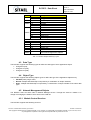
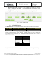
Doc.: CAS-RCCIPC-DTS-0001
RCCIPC - Data Sheet
Issue: 6
Date: 08/05/2014
Page: 1 of 53
RCCIPC - Data Sheet
Date:
Prepared by:
P. Tosi
Verified by:
W. Errico
08/05/2014
Approved by:
F. Bigongiari (Project Manager)
08/05/2014
File name: CAS-RCCIPC-DTS-0001_Issue6.docx
08/05/2014
RCCIPC - Data Sheet
The copyright of this document is vested in SITAEL S.p.A.. However, no responsibility is assumed by SITAEL S.p.A. for its use, nor for
any infringements of patents or other rights of third parties that may result from its use.
Doc.: CAS-RCCIPC-DTS-0001
RCCIPC - Data Sheet
Issue: 6
Date: 08/05/2014
Page: 2 of 53
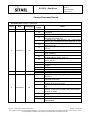
Change Document Record
Document title: RCCIPC - Data Sheet
Issue
Date
Total pages
1
10/06/2011
36
Modified
pages
All
All
10
14
14
16
18
2
21/09/2011
44
20
24
26
30
31
32
3
20/07/2012
41
34
34
38
39
All
9
13
14
4
31/10/2012
53
15
16
16
21
File name: CAS-RCCIPC-DTS-0001_Issue6.docx
Notes
First issue of the document
Replaced all CCIPC references with RCCIPC in all
paragraphs.
Modified Tab. 4-2: FPGA family files.
In “TPDO AO” table in §5.1.2 replaced RPDO_AO
description with TPDO_AO.
In “RCCIPC_AO” and “RCCIPC_AO – Total Bytes”
tables in §5.1.2 modified Sub-Index upper limit to 254.
In “Block Size” table in §5.2.3 modified Sub-Index
upper limit to 254.
In §6 modified periphery signal names in Fig. 6-1and
Tab. 6-1.
Added §6.1.3 Node-ID Acquisition and Modification
In Tab. 7-1 modified BLKIDL , BLKDL, BlkIUL and
BlkUL definitions.
Modified ID field in Tab. 7-2.
Modified Address value in Tab. 7-3
Modified Default values of Sub-Index 0 and 1 of Index
2003 in Tab. 9-1.
Modified Default values in Tab. 9-3
In Tab. 9-5 - IRQ status register, added SDO Dw and
Ul flags
Modified TRX IRQ pseudo code box.
Removed reference to SYNCH_IRQ management.
Updated §11 - RCCIPC Resource Occupation
Updated §12 - RCCIPC Timing Characteristics
In all document replaced Actel reference with
Microsemi.
In §4 explained in more details the CANopen features
supported by RCCIPC.
In §5.1 highlighted that SW requirement refers to the
minimum that has been tested
In §5.2 added Fig. 5-2 adding more details of SRC
files.
Added §5.2.1 with a detailed description of Libraries
directory. A description of RAM model characteristics
has been included.
Incorporate previous TESTBENCH directory section in
§5.2.1.
Renamed §5.2.2. Added also HurriCANe file list.
In §6.2 added basic information on FSM
implementation.
RCCIPC - Data Sheet
The copyright of this document is vested in SITAEL S.p.A.. However, no responsibility is assumed by SITAEL S.p.A. for its use, nor for
any infringements of patents or other rights of third parties that may result from its use.
Doc.: CAS-RCCIPC-DTS-0001
RCCIPC - Data Sheet
Issue: 6
Date: 08/05/2014
Page: 3 of 53
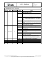
Document title: RCCIPC - Data Sheet
Issue
Date
Total pages
Modified
pages
26
28
33
32
34
38
50
51
9
11
12
21
24
32
5
04/12/2012
52
36
38
50
6
08/05/2014
53
File name: CAS-RCCIPC-DTS-0001_Issue6.docx
42
44
Notes
Added §7.1.4 with a simple description of Reset
distribution inside RCCIPC
In §8 modified instructions for CCIPC simulations and
test execution.
Added §8.3 describing simulation Log file.
In Tab. 8-1 modified BlkDL parameter and rst_comm
function.
Split §8.4 in two paragraphs:
8.4.1 - RCCIPC default tests and 8.4.2 - User defined
tests.
§10 has been completely reviewed
In §13 replace Segment with Block in Parameter filed
of “SDO Download Block” and “SDO Upload Block”
tables.
In §14.3 inserted additional information on EDAC
feature implemented in RCCIPC
In §4.1 added that RCCIPC is a SYNC consumer
In §4.5.3 substituted Ctoggle with Ntoggle.
In §4.7.2 added that SDO has to address subindex 1
to correctly start.
In §6.2 removed warning on FSM implementation.
In §7 added information on RCCIPC endianness.
In Tab. 8-1 added explanation of cflag parameter of
BlkDL function.
In §9.1.1 removed warning on FSM implementation.
In §10.1 changed host access type of :
- IRQ Mask-clear register;
In §13 modified:
- Note about Heartbeat consumer counter reset;
- parameters name of SDO Download and Upload
Block to match the standard CANopen nomenclature;
In §10.1 added information on IRQ masking
In §10.1 added Tab. 10-2.
RCCIPC - Data Sheet
The copyright of this document is vested in SITAEL S.p.A.. However, no responsibility is assumed by SITAEL S.p.A. for its use, nor for
any infringements of patents or other rights of third parties that may result from its use.
Doc.: CAS-RCCIPC-DTS-0001
RCCIPC - Data Sheet
Issue: 6
Date: 08/05/2014
Page: 4 of 53
Table of Contents
1
INTRODUCTION....................................................................................................................................... 6
2
DOCUMENTS ........................................................................................................................................... 7
2.1
Reference Documents ..................................................................................................... 7
3
LIST OF ACRONYMS AND ABBREVIATIONS ....................................................................................... 8
4
CANOPEN OVERVIEW ............................................................................................................................ 9
4.1
Communication Model ..................................................................................................... 9
4.2
Object Dictionary ............................................................................................................. 9
4.3
Data Type ...................................................................................................................... 10
4.4
Object Type ................................................................................................................... 10
4.5
Network Management Objects....................................................................................... 10
4.5.1
4.5.2
4.5.3
Module Control Services ............................................................................................................ 10
Bootup Service ........................................................................................................................... 11
Error Control Service and Bus Redundancy .............................................................................. 11
4.6
Communication Objects................................................................................................. 11
4.7
Process Data Object (PDO) ........................................................................................... 11
4.7.1.1
TPDO ................................................................................................................................ 11
4.7.1.1.1 Asynchronous ............................................................................................................... 11
4.7.1.2
RPDO ................................................................................................................................ 12
4.7.1.2.1 Asynchronous ............................................................................................................... 12
4.7.2 Service Data Object (SDO) ........................................................................................................ 12
5
IP CORE DATABASE ............................................................................................................................. 13
5.1
Software Requirement ................................................................................................... 13
5.2
SRC Directory ............................................................................................................... 14
5.2.1
5.2.1
5.2.2
6
LIBRARIES Directory ................................................................................................................. 15
TESTBENCH Directory .............................................................................................................. 16
CAN Bus Controller .................................................................................................................... 16
5.3
SIM Script Directory....................................................................................................... 16
5.4
SYN Script Directory...................................................................................................... 17
5.5
FIT Script Directory........................................................................................................ 18
5.6
CONFIG File Directory................................................................................................... 18
5.7
CONFIG Tool Directory ................................................................................................. 18
RCCIPC CONFIGURATION ................................................................................................................... 19
6.1
6.1.1
6.1.2
6.2
6.2.1
RCCIPC Object Dictionary............................................................................................. 19
Configurable Parameters ........................................................................................................... 19
Application Objects .................................................................................................................... 20
RCCIPC CANOpen Services ......................................................................................... 21
Receive PDO Service ................................................................................................................ 21
File name: CAS-RCCIPC-DTS-0001_Issue6.docx
RCCIPC - Data Sheet
The copyright of this document is vested in SITAEL S.p.A.. However, no responsibility is assumed by SITAEL S.p.A. for its use, nor for
any infringements of patents or other rights of third parties that may result from its use.
Doc.: CAS-RCCIPC-DTS-0001
RCCIPC - Data Sheet
Issue: 6
Date: 08/05/2014
Page: 5 of 53
6.2.2
6.2.3
Transmit PDO Service ............................................................................................................... 22
SDO Service .............................................................................................................................. 22
7
INTERFACE ............................................................................................................................................ 24
7.1.1 IRQ & External Trigger ............................................................................................................... 25
7.1.2 CAN Bus Selection .................................................................................................................... 26
7.1.3 Node-ID Acquisition and Modification ........................................................................................ 26
7.1.4 Reset Distribution ....................................................................................................................... 26
8
SIMULATION ENVIRONMENT .............................................................................................................. 28
8.1
RCCIPC Core Test-Bench ............................................................................................. 30
8.2
Input Stimuli Format ...................................................................................................... 31
8.3
Output Test Log File ...................................................................................................... 33
8.4
Test Procedures Simulation ........................................................................................... 34
8.4.1
8.4.2
9
RCCIPC default tests ................................................................................................................. 34
User defined tests ...................................................................................................................... 35
SYNTHESIS AND FITTING SCRIPTS ................................................................................................... 36
9.1
Microsemi (RT)AX FPGA............................................................................................... 36
9.1.1
9.1.2
10
Synthesis.................................................................................................................................... 36
Fitting ......................................................................................................................................... 37
RCCIPC MEMORY MAPPING ............................................................................................................... 38
10.1
Configuration & Status Area .......................................................................................... 38
10.1.1
10.2
11
IRQ handling .......................................................................................................................... 44
AOs Addressing............................................................................................................. 46
CONFIGURATION TOOL ....................................................................................................................... 47
11.1
VHDL Configuration File ................................................................................................ 47
11.2
RCCIPC Configuration Tool ........................................................................................... 48
12
RCCIPC Resource Occupation ............................................................................................................ 49
13
RCCIPC Timing Characteristics .......................................................................................................... 50
14
RCCIPC Portability ................................................................................................................................ 51
14.1
CAN Bus Controller ....................................................................................................... 51
14.2
FPGA Technology ......................................................................................................... 51
14.3
Rad-Hard Technique ..................................................................................................... 51
File name: CAS-RCCIPC-DTS-0001_Issue6.docx
RCCIPC - Data Sheet
The copyright of this document is vested in SITAEL S.p.A.. However, no responsibility is assumed by SITAEL S.p.A. for its use, nor for
any infringements of patents or other rights of third parties that may result from its use.
Doc.: CAS-RCCIPC-DTS-0001
RCCIPC - Data Sheet
Issue: 6
Date: 08/05/2014
Page: 6 of 53
1
INTRODUCTION
This document acts as Reduced Can Controller IP Core data sheet and toolset user manual. The Core
features and its development environment are here described.
A quick start approach to RCCIPC should pass through the following steps:
1) Set-up the RCCIPC database inserting HurriCANe core (see §5.2.2). The IP Core Database is
presented in §4 with a detailed description its directories structure and main files
2) Run standard configuration tests. The simulation environment set-up is presented in §8.4, with
explicit information about the files involved in the simulation process.
3) Simulate application specific core instance the explanation how to customise the simulation
environment and the compiler tool are provided in §8.
4) Synthetize and Fit application specific configuration. Section §9 provide users with basic
instructions for synthetizing and fitting of the RCCIPC core instance in the Microsemi RTAX250
technology.
RCCIPC area occupation and operating frequency for different FPGA technologies are reported in §12.
In §13 an estimation of elaboration time of the main CANOpen features is reported.
A brief description of RCCIPC portability is illustrated §14.
File name: CAS-RCCIPC-DTS-0001_Issue6.docx
RCCIPC - Data Sheet
The copyright of this document is vested in SITAEL S.p.A.. However, no responsibility is assumed by SITAEL S.p.A. for its use, nor for
any infringements of patents or other rights of third parties that may result from its use.
Doc.: CAS-RCCIPC-DTS-0001
RCCIPC - Data Sheet
Issue: 6
Date: 08/05/2014
Page: 7 of 53
2
DOCUMENTS
2.1 Reference Documents
[RD 1] CiA Draft Standard 301 Version 4.02
[RD 2] CiA Draft Standard 306 Version 1.3
File name: CAS-RCCIPC-DTS-0001_Issue6.docx
RCCIPC - Data Sheet
The copyright of this document is vested in SITAEL S.p.A.. However, no responsibility is assumed by SITAEL S.p.A. for its use, nor for
any infringements of patents or other rights of third parties that may result from its use.
Doc.: CAS-RCCIPC-DTS-0001
RCCIPC - Data Sheet
Issue: 6
Date: 08/05/2014
Page: 8 of 53
3
LIST OF ACRONYMS AND ABBREVIATIONS
Abbreviation
AHB
AMBA
AO
CAN
CAN MST
CCIPC
CiA
COB-ID
DCF
EDAC
EDS
FPGA
Meaning
Advanced High-performance Bus
Advanced Microcontroller Bus Architecture
Application Object
Controller Area Network
CAN Master
CANOPEN Controller IP core
CAN In Automation
Communication Object Identifier
Device Configuration File
Error Detection And Correction
Electronic Data Sheet
Field Programmable Gate Array
FSM
Finite State Machine
GUI
Graphical User Interface
HB
Heartbeat
HW
Hardware
IRQ
Interrupt Request
NMT
Network Management
OD
Object Dictionary
PDO
Process Data Object
RAM
Random Access Memory
RCCIPC
ROM
RPDO
SDO
SW
Reduced CANOPEN Controller IP core
Read Only Memory
Receive PDO
Service Data Object
Software
SYNC
Synchronization Object
TPDO
Transmit PDO
U8
Unsigned 8
U16
Unsigned 16
U32
Unsigned 32
UUT
VHDL
Unit Under Test
VHSIC (Very High Speed Integrated Circuit) HW Description Language
File name: CAS-RCCIPC-DTS-0001_Issue6.docx
RCCIPC - Data Sheet
The copyright of this document is vested in SITAEL S.p.A.. However, no responsibility is assumed by SITAEL S.p.A. for its use, nor for
any infringements of patents or other rights of third parties that may result from its use.
Doc.: CAS-RCCIPC-DTS-0001
RCCIPC - Data Sheet
Issue: 6
Date: 08/05/2014
Page: 9 of 53
4
CANOPEN OVERVIEW
In this paragraph, an overview of CANOpen services supported by the Reduced CANOpen Controller IP
Core (RCCIPC) core is provided.
The CAN in Automation (CiA) Standard “CANopen Application Layer and Communication Profile” ([RD 1])
is used as reference document for the CANopen standard.
4.1 Communication Model
The RCCIPC is designed to act as:
• SLAVE node in a CANopen network, responding to a master request;
• SERVER node for SDO Download and Upload services;
• PRODUCER and CONSUMER node for PDO and Heartbeat services;
• CONSUMER of SYNC message;
4.2 Object Dictionary
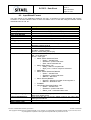
The RCCIPC supports the Object Dictionary implementation. A limited set of Object Dictionary entries are
supported as shown in next table.
The RCCIPC Object Dictionary foresees a dedicated area (entries starting from index 2000h) that defines
RCCIPC specific parameters and two macro areas (Read-Write and Read-Only) that allows user to define
its specific Application Objects.
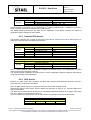
Index
1016h
Sub-Index
Entry Name
0h
Consumer Heartbeat timer
1h
Master & Consumer Heartbeat time
1017h 0h
Producer Heartbeat time
SDO Server Parameter
0h
Server SDO Parameter
1200h 1h
COB-ID client-server
2h
COB-ID server-client
RPDO Parameter
0h
RPDO Communication
1400h 1h
COB-ID
2h
Transmission Type
0h
RPDO Mapping
1600h
1h – 8h
Mapping Parameter
TPDO Parameter
0h
RPDO Communication
1h
COB-ID
2h
Transmission Type
1800h
3h
Inhibit Time
4h
Reserved
5h
Inhibit Time
0h
TPDO Mapping
1A00h
1h – 8h
Mapping Parameter
RCCIPC Parameter
0h
2000h 1h
Bdefault
2h
Ttoggle
File name: CAS-RCCIPC-DTS-0001_Issue6.docx
RCCIPC - Data Sheet
The copyright of this document is vested in SITAEL S.p.A.. However, no responsibility is assumed by SITAEL S.p.A. for its use, nor for
any infringements of patents or other rights of third parties that may result from its use.
Doc.: CAS-RCCIPC-DTS-0001
RCCIPC - Data Sheet
Issue: 6
Date: 08/05/2014
Page: 10 of 53
Index
Sub-Index
3h
4h
2001 0h
0h
2002h 1h
2h
0h
1h
2h
2003h 3h
4h
5h
6h
Read-Write Area
6000h 0h
1h
2h
6001h 0h
1h
2h
0h – 254h
6002h
Entry Name
Ntoggle
Ctoggle
Filler entry
ID base
ID mask
HurriCANe configuration
HurriCANe & CCIPC status
IRQ status
IRQ mask-clear
EDAC error
TPDO Trig
RPDO AO1
RPDO AO2
TPDO AO1
TPDO AO2
SDO –
User Defined Application Objects
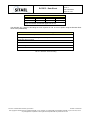
Tab. 4-1: RCCIPC Object Dictionary Layout.
4.3 Data Type
The RCCIPC supports the following types to define the data type of each Application Object:
• Unsigned 8 (U8);
• Unsigned 16 (U16);
• Unsigned 32 (U32).
4.4 Object Type
The RCCIPC supports the following Object types to define the type of the Application Objects entry
• Variable (VAR): single value;
• Record: multiple data field object composed by a combination of simple variables;
• Array: multiple data field object composed by a combination of simple variable of the same data
type.
4.5 Network Management Objects
The RCCIPC works as slave node in Network Manager service. Through this service a master is in
charge of managing the status of each slave in the CAN net.
4.5.1 Module Control Services
The RCCIPC supports the following services:
File name: CAS-RCCIPC-DTS-0001_Issue6.docx
RCCIPC - Data Sheet
The copyright of this document is vested in SITAEL S.p.A.. However, no responsibility is assumed by SITAEL S.p.A. for its use, nor for
any infringements of patents or other rights of third parties that may result from its use.
Doc.: CAS-RCCIPC-DTS-0001
RCCIPC - Data Sheet
Issue: 6
Date: 08/05/2014
Page: 11 of 53
•
•
•
•
•
Start Remote Node: RCCIPC enters in OPERATIONAL state;
Stop Remote node: RCCIPC enters in STOP state;
Enter Pre-Operational: RCCIPC enters in PRE-OPERATIONAL state;
Reset Node: RCCIPC enters RESET APPLICATION state;
Reset Communication: RCCIPC enters RESET COMMUNICATION state.
RCCIPC supports a special feature that allows RCCIPC to enter directly in OPERATIONAL state at the
end of initialization phase when a dedicated flag is active.
4.5.2 Bootup Service
RCCIPC supports the Boot-up service signaling to the Master that the initialization phase ended.
4.5.3 Error Control Service and Bus Redundancy
The RCCIPC supports the Heartbeat protocol to detect failures in a CAN network. RCCIPC is in charge of
receiving and transmitting Heartbeat messages.
When RCCIPC does not receive the Heartbeat message from the Master node it generates an “Heartbeat
event”.
This event is used by RCCIPC to implement the “Bus Redundancy Management” protocol. Through this
protocol RCCIPC is able to control two CAN buses (nominal and redundant). RCCIPC periphery is
furnished with a bus selection flag that, in a multiplexing way, allows defining which is the currently CAN
active bus.
Two parameters are available to control the redundancy protocol:
• Ttoggle counter;
• Ntoggle counter.
The Ttoggle counter defines the maximum number of Heartbeat events causing a bus switch.
The Ntoggle counter defines the maximum number of bus toggling before RCCIPC stops the redundancy
process.
4.6 Communication Objects
4.7 Process Data Object (PDO)
The real time data transfer is performed by the “PDO” service. Two kinds of PDO are supported:
• Transmit PDO (TPDO) – RCCIPC transmits data;
• Receive PDO (RPDO) – RCCIPC receives data.
4.7.1.1 TPDO
The RCCIPC supports only the Asynchronous transmission modes for TPDO service associated to a
static Application Objects of 8 bytes (6001h).
4.7.1.1.1
Asynchronous
The transmission of this type of TPDO is associated to the following trigger:
• Event trigger : external host device issues a TPDO transmission request;
The two timer parameters (Event Time and Inhibit Time) are not supported.
File name: CAS-RCCIPC-DTS-0001_Issue6.docx
RCCIPC - Data Sheet
The copyright of this document is vested in SITAEL S.p.A.. However, no responsibility is assumed by SITAEL S.p.A. for its use, nor for
any infringements of patents or other rights of third parties that may result from its use.
Doc.: CAS-RCCIPC-DTS-0001
RCCIPC - Data Sheet
Issue: 6
Date: 08/05/2014
Page: 12 of 53
4.7.1.2 RPDO
The RCCIPC supports only the Asynchronous elaboration modes for RPDO service associated to a
static Application Objects of 8 bytes (6000h).
4.7.1.2.1
Asynchronous
The CCIPC starts the elaboration of this type of RPDO immediately after its reception.
4.7.2 Service Data Object (SDO)
The SDO service allows a client to access the Object Dictionary of a server node to read (SDO Upload)
or write (SDO Download) specific Object Dictionary entries.
The RCCIPC supports only SDO Block service, without CRC feature, associated to a static Application
Objects (6002h) that user can configure. The SDO transfer has to address the subindex 1 of entry 6002h
to start correctly.
RCCIPC supports the SDO Abort service. It is in charge signalling errors if a SDO protocol error is
detected and stopping SDO transfer when an SDO abort is received.
File name: CAS-RCCIPC-DTS-0001_Issue6.docx
RCCIPC - Data Sheet
The copyright of this document is vested in SITAEL S.p.A.. However, no responsibility is assumed by SITAEL S.p.A. for its use, nor for
any infringements of patents or other rights of third parties that may result from its use.
Doc.: CAS-RCCIPC-DTS-0001
RCCIPC - Data Sheet
Issue: 6
Date: 08/05/2014
Page: 13 of 53
5
IP CORE DATABASE
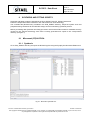
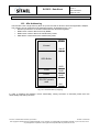
The RCCIPC database tree is described. Fig. 5-1
RCCIPC DB
SRC
CAN_CORE
LIBRARIES
TESTBENCH
SIM_SCRIPT
SYN_SCRIPT
FIT_SCRIPT
CONFIG_FILE
CONFIG_TOOL
Fig. 5-1: RCCIPC database tree.
It is composed of the following directories:
•
•
•
•
•
•
SRC – It includes all the VHDL files that constitutes the RCCIPC architecture
SIM SCRIPT – It includes the scripts and file used to compile the RCCIPC core
SYN SCRIPT – It includes files needed to perform the RCCIPC synthesis process
FIT SCRIPT – It includes files needed to perform the RCCIPC fitting process
CONFIG FILE – it includes the configuration files needed by the RCCIPC configuration tool
CONFIG TOOL – it includes the executable RCCIPC configuration tool
5.1 Software Requirement
The minimum software requirement for Linux kernel and GNU tools versions that has been tested is the
following:
File name: CAS-RCCIPC-DTS-0001_Issue6.docx
RCCIPC - Data Sheet
The copyright of this document is vested in SITAEL S.p.A.. However, no responsibility is assumed by SITAEL S.p.A. for its use, nor for
any infringements of patents or other rights of third parties that may result from its use.
Doc.: CAS-RCCIPC-DTS-0001
RCCIPC - Data Sheet
Issue: 6
Date: 08/05/2014
Page: 14 of 53
Linux Kernel 2.6.27-11-generic
GNU make 3.81
gcc version 4.3.2
Perl V5.10.0
perl-Tk V804.028
All the RCCIPC SW features has been tested using Ubuntu 8.10 (Linux Kernel 2.6.27-11-generic) and
Ubuntu 9.10 (Linux Kernel 2.6.31-22-generic).
5.2 SRC Directory
The SRC directory contains the source files that fully describe the RCCIPC core in behavioural
synthesizable VHDL format, and (into separated subdirectories) the additional files needed to map
RCCIPC in specific technologies, to compose its simulation environment, and to house the low level CAN
controller core.
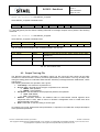
The RCCIPC proper VHDL source files are listed in Tab. 5-1:
Name
RCCIPCconf.vhd
CANopen_pkg.vhd
mem_tech.vhd
EDAC_pack.vhd
Description
RCCIPC configuration file
CANopen constant parameters
Definition of memory blocks using specific technology
Definition of EDAC package
RCCIPC.vhd
arbiter.vhd
RCCIPC_interface.vhd
ccipc_can.vhd
NetworkManager.vhd
event_handler.vhd
OD_handler.vhd
RCCIPC_FSM.vhd
edac_calc.vhd
adder.vhd
reset_sync.vhd
MemRF.vhd
RCCIPC top level
Memory arbiter
RCCIPC CAN interface controller
RCCIPC can module. It embodies both RCCIPC_interface and CAN
controller entities.
Network Manager
Event handler
CANopen communication protocol handler
FSM implementation of the CANopen protocol services
EDAC module
Adder module
Reset synchroniser module
Register handler module
Makefile
Makefile.mem
VHDL compilation file
Technology Makefile
Tab. 5-1: RCCIPC SRC files.
The RCCIPC architecture composed of:
• CAN interface: composed by the CAN controller (can_core) and its interface manager
(RCCIPC_interface);
• Messages queues: they store message received (MsgIn Controller) and message to be
transmitted(MsgOut Controller). The queues are implemented using memory devices (MsgIn
Queue,MsgOut Queue);
• Network Manager: it is the manager of the Network Management Services, controlling the NMT
state and performing the Bus Redundancy management (Network Manager);
File name: CAS-RCCIPC-DTS-0001_Issue6.docx
RCCIPC - Data Sheet
The copyright of this document is vested in SITAEL S.p.A.. However, no responsibility is assumed by SITAEL S.p.A. for its use, nor for
any infringements of patents or other rights of third parties that may result from its use.
Doc.: CAS-RCCIPC-DTS-0001
RCCIPC - Data Sheet
Issue: 6
Date: 08/05/2014
Page: 15 of 53
•
Object Dictionary Handler: composed by an event scheduler (event_handler) that controls the
engine of the RCCIPC (OD handler) in order to elaborates the Communication services
(RPDO,TPDO,SDO)
• Memory controller: it is the module that allows accessing the whole Object Dictionary.
The following figure illustrates the dependencies between the modules constituting the RCCIPC.
Fig. 5-2: RCCIPC SRC directory tree.
5.2.1 LIBRARIES Directory
The LIBRARIES subdirectory contains the files used to adapt the RCCIPC to different FPGA families.
Directory
ACTEL_AX
TECH_GEN
File Name
ax_ram512x8.vhd (not furnished)
tech_generic.vhd
Description
RAM 512x8 bit RAM model
RAM 512x8 bit Generic RAM model
Tab. 5-2: RCCIPC FPGA technology files.
Currently the RCCIPC supports only the Microsemi Axcelerator family. Users have to generate the
correspondent technology memory file. The following characteristics have to be used to generate a
supported memory device:
Name
Type
Write Width
Read Width
Write Depth
Enable Pin
Write Enable
Read Enable
Pipeline
Reset
Clock
Axcelerator
ax_ram512x8
Single Port RAM
8
8
512
Not available
High
High
No
No
Single
Tab. 5-3: RCCIPC RAM Model characteristics.
The generated file has to be included in the appropriate directory according to the target FPGA family.
File name: CAS-RCCIPC-DTS-0001_Issue6.docx
RCCIPC - Data Sheet
The copyright of this document is vested in SITAEL S.p.A.. However, no responsibility is assumed by SITAEL S.p.A. for its use, nor for
any infringements of patents or other rights of third parties that may result from its use.
Doc.: CAS-RCCIPC-DTS-0001
RCCIPC - Data Sheet
Issue: 6
Date: 08/05/2014
Page: 16 of 53
5.2.1 TESTBENCH Directory
The TESTBENCH subdirectory contains the files needed to set up the RCCIPC core simulation
environment.
The files needed for simulation are reported in the following table:
Name
RCCIPC_tb.vhd
Description
RCCIPC testbench
parser.vhd
Emulator of CAN master and HOST interface
CAN3MB:
Can.vhd
Interface.vhd
singleshot_true.vhd
singleshot_false.vhd
AUCAN3_8051 is an hdl model of CAN Controller interface for 8bit
microcontroller and it’s used to emulate a CAN master node.
Tab. 5-4: Test bench source files.
5.2.2 CAN Bus Controller
The RCCIPC core has been designed to embody the HurriCANe Core in its version 5.2.4. The source
files are not directly included in the RCCIPC database because subjected to different patent restrictions.
ESA distributes the HurriCANe_5.2.4 core under its specific license.
To insert the HurriCANe controller in the RCCIPC database, the HurriCANe_5.2.4 source files have to be
simply copied in the CAN_CORE directory.
The list of HurriCANe files is reported below:
• CANCore.vhd;
• CANCoreConfiguration.vhd;
• CANMessageStates.vhd;
• CANRx.vhd;
• CANTx.vhd
• CRCCalc.vhd;
• ErrFrameGen.vhd;
• ErrorCounters.vhd;
• StuffHandler.vhd;
• Synchro.
5.3 SIM Script Directory
The SIM_SCRIPT directory contains all the files that compose the IP core test procedures and the scripts
needed to build new input stimuli for RCCIPC simulation.
Name
RCCIPCTestWriter.pl
RCCIPC_test.sh
Description
Perl script to generate stimuli file for the parser module
Shell script to perform automatically predefined RCCIPC test procedures
Tab. 5-5: Simulation scripts.
For each test procedure, these files are included:
File name: CAS-RCCIPC-DTS-0001_Issue6.docx
RCCIPC - Data Sheet
The copyright of this document is vested in SITAEL S.p.A.. However, no responsibility is assumed by SITAEL S.p.A. for its use, nor for
any infringements of patents or other rights of third parties that may result from its use.
Doc.: CAS-RCCIPC-DTS-0001
RCCIPC - Data Sheet
Issue: 6
Date: 08/05/2014
Page: 17 of 53
•
•
•
VHDL constants configuration file (see §11.1 for file content)
Input stimuli in .in format (see §8.2 for file format)
Expected results file.
The VRP_TB sub-directory includes all the test procedures files. and the full list of the RCCIPC test
procedure is contained in Tab. 5-6.
Test Name
TP5113_boot
TP5123_nmt_s1
TP5123_nmt_s2
TP5123_nmt_s3
TP5123_nmt_s4
TP5133_NMT_filtering
TP5143_hbt
TP5213_asyncRPDO
TP5223_syncrx
TP5323_asynchTPDO
TP5443_DW_block.
TP5453_UL_block.
TP5462_AbortRx
TP5462_ccs
TP5462_IndexError
TP5462_SizeError
TP5462_blksize_err
TP5462_seq_err
TP5513_hbc_tce
TP5523_Ctoggle
TP5613_parallel#1
TP5623_parallel#2
Description
RCCIPC boot-up message test
RCCIPC NMT state transition test
RCCIPC NMT state transition vs Communication Objects filtering
Heartbeat transmission test
Asynchronous RPDO test
Reception of synch message
Asynchronous RPDO test
SDO Upload segmented test
SDO Upload segmented test
Reception of SDO abort test
SDO Error Decoding and Transmission of Abort message test
Heartbeat reception and Ttoggle expiration test
Ctoggle expiration and Bus switch test
RCCIPC handling of different task simultaneously test
Tab. 5-6: RCCIPC test list.
The ADDON_TB sub-directory includes a set of additional tests that are performed to cover more
CANopen protocol aspects.
The instructions to run all test procedures are provided in §8.4.
5.4 SYN Script Directory
The SYN_SCRIPT houses the files needed to synthetize the RCCIPC for RTAX technology.
Two types of script files are included:
•
•
The project (.prj) files holds the reference to all the VHDL source files and includes the
technology specific settings.
The constraint (.sdc) files keeps the system clock and peripheral timing constraints for the
RCCIPC design.
The section §9 provides the user with a basic procedure for the core synthesis with Synplify Synthesizer
Tool.
File name: CAS-RCCIPC-DTS-0001_Issue6.docx
RCCIPC - Data Sheet
The copyright of this document is vested in SITAEL S.p.A.. However, no responsibility is assumed by SITAEL S.p.A. for its use, nor for
any infringements of patents or other rights of third parties that may result from its use.
Doc.: CAS-RCCIPC-DTS-0001
RCCIPC - Data Sheet
Issue: 6
Date: 08/05/2014
Page: 18 of 53
5.5 FIT Script Directory
FIT SCRIPT directory includes the project targeted to RTAX-250 FPGA target device.
The basic instructions to build a fitting project are included in §9.
5.6 CONFIG File Directory
The directory contains the VHDL configuration file produced by the Configuration tool.
All the VHDL files needed to perform the test listed in Tab. 5-6 are available in VRP_CF sub-directory.
5.7 CONFIG Tool Directory
The directory contains the executable file of the RCCIPC Configuration tool (a Perl-Tk script) whose
description is reported in §11.
File name: CAS-RCCIPC-DTS-0001_Issue6.docx
RCCIPC - Data Sheet
The copyright of this document is vested in SITAEL S.p.A.. However, no responsibility is assumed by SITAEL S.p.A. for its use, nor for
any infringements of patents or other rights of third parties that may result from its use.
Doc.: CAS-RCCIPC-DTS-0001
RCCIPC - Data Sheet
Issue: 6
Date: 08/05/2014
Page: 19 of 53
6
RCCIPC CONFIGURATION
The RCCIPC is a reduced version of the CCIPC core designed to furnish a limited set of CANopen
services using a pre-defined Object-Dictionary configuration.
6.1 RCCIPC Object Dictionary
The OD configuration is reported in Tab. 6-1. In the last column is reported the Hardware implementation
of each entry:
• Not available means that no HW logic is used to allow user to read or write the value because it
has a pre-defined value
• Available means that HW logic is used to allow user to read or write the value
Index
Entry Name
Hardware implementation
1000h
Device Type
Not available
1001h
Error register
Not available
1005h
COB-ID synch
Not available
1007h
Synchronous Window length
Not available
1016h
Heartbeat consumer time
Not available
1017h
Producer Heartbeat time
Not available
1018h
Identity object
Not available
1200h
Server SDO
Not available (*)
1400h
RPDO Communication Parameter
Not available (*)
1600h
RPDO Mapping Parameter
Not available
1800h
TPDO Communication Parameter
Not available (*)
1A00h
TPDO Mapping Parameter
Not available
2000h
Redundancy Management
Available in Read-only mode
2002h
Node parameters
Available in Read-only mode
2003h
RCCIPC status & configuration
Available
6000h
RPDO Application Objects
Available
6001h
TPDO Application Objects
Available
6002h
SDO Application Objects
Available
(*) The value of the parameters of these entries depends on NodeID assigned to RCCIPC.
The NodeID is sampled after Reset phase using a dedicated interface pins.
Tab. 6-1: RCCIPC OD structure.
6.1.1 Configurable Parameters
A VHDL file (RCCIPCconf.vhd) is used to define the RCCIPC configuration, through a set of VHDL
constant. The relationship between OD entry and configurable mapping parameter is reported in Tab. 6-2.
Index
1016h
1017h
2002h
Entry Name
Heartbeat consumer time
Producer Heartbeat time
Node parameters
Redundancy Management
2000h
File name: CAS-RCCIPC-DTS-0001_Issue6.docx
Configurable Constant
CONS_HB
PROD_HB
NODEID (used during simulation phase)
T_TOGGLE
N_TOGGLE
B_DEF
RCCIPC - Data Sheet
The copyright of this document is vested in SITAEL S.p.A.. However, no responsibility is assumed by SITAEL S.p.A. for its use, nor for
any infringements of patents or other rights of third parties that may result from its use.
Doc.: CAS-RCCIPC-DTS-0001
RCCIPC - Data Sheet
Issue: 6
Date: 08/05/2014
Page: 20 of 53
Index
Entry Name
RCCIPC status & configuration
2003h
Configurable Constant
RSJ_VAL
PS1_VAL
PS2_VAL
BPR_VAL
AUTO_OPER
EDAC_REG_VAL
Tab. 6-2: Configurable parameters vs OD entry.
The explanation on its parameter is here reported:
• NODEID - This field allows defining the RCCIPC Node ID. This value is used only for
simulation scope. During normal operation, the NodeID is defined using dedicated input port pins;
• RSJ_VAL, PS1_VAL, PS2_VAL and BPR_VAL - These constants have to be set to obtain
the desired Bit-Rate according to system frequency value. RCCIPC supports a working frequency
in the range from 10MHz to 16 MHz. The supported Bit-Rate are
1 Mbps
500 Kbps
250 Kbps
125 Kbps
• CONS_HB - It allows specifying the expected Heartbeat cycle time, expressed with
millisecond granularity and the COB-ID of Master node.
• PROD_HB – It allows specifying the cycle time of the heartbeat object, expressed with
millisecond granularity.
• T_TOGGLE – It defines the number of Heartbeat event that can occur before Bus switching;
• N_TOGGLE – It defines the maximum number of bus switching.
• B_DEF – It defines the Default Bus
• AUTO_OPER – It defines if RCCIPC enters automatically (‘1’) or not(‘0’) in Operational State
after initialization phase;
• EDAC_REG_VAL – It defines the value of the EDAC error register.
6.1.2 Application Objects
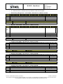
RCCIPC OD layout foresees only 3 Application Objects which have the following structure:
RPDO AO
Index
Sub-Index
0
1
2
Description
sub-index supported
RPDO_AO1
RPDO_AO2
Value
2
U32
U32
Sub-Index
0
1
2
Description
sub-index supported
TPDO_AO1
TPDO_AO2
Value
2
U32
U32
RCCIPC_AO
Index
Sub-Index
0
0x6002
1-254
Description
sub-index supported
AO_n
Value
255
U8-U16-U32
0x6000
TPDO AO
Index
0x6001
File name: CAS-RCCIPC-DTS-0001_Issue6.docx
RCCIPC - Data Sheet
The copyright of this document is vested in SITAEL S.p.A.. However, no responsibility is assumed by SITAEL S.p.A. for its use, nor for
any infringements of patents or other rights of third parties that may result from its use.
Doc.: CAS-RCCIPC-DTS-0001
Issue: 6
RCCIPC - Data Sheet
Date: 08/05/2014
Page: 21 of 53
The RPDO_AO and TPDO_AO entries are composed of 2 sub-indexes of U32 and are used to store the
data values elaborated during RPDO and TPDO transfers respectively.
The RCCIP_AO entry represents a single buffer used during SDO transfers. It supports only 32, 64, 128
and 254 sub-indexes, defined as U8,U16 or U32.
RCCIPC_AO - Total Bytes
Sub-Index len
U8
32
32
64
64
128
128
254
254
U16
64
128
256
508
U32
128
256
512
1016
6.2 RCCIPC CANOpen Services
The RCCIPC is in charge of supporting the following CANOpen services:
• NMT state transitions;
• Synch consumer;
• Heartbeat receiver and producer;
• SDO block;
• Asynchronous RPDO and TPDO ;
• Redundancy manager
The implementation of the RPDO, TPDO and SDO services is performed by the specific Finite State
Machine module (RCCIPC_FSM.vhd) available in the SRC directory.
The FSM executes the following “macro” operations:
• Object Dictionary Initialisation;
• RPDO elaboration;
• TPDO elaboration;
• SDO elaboration.
The FSM is implemented exploiting only combinational logic and it works as “big multiplexers” returning
the execution code according to the input address. Each “macro” operation is implemented as a
sequence of Logic, Arithmetic and Memory operations for:
• Registers loading with constants
• Operands moving among different registers
• Arithmetic operations
• Logic compare and bit check
• Read/write memory operations
In the next paragraphs, how RCCIPC manages the RPDO, TPDO and SDO services is explained.
6.2.1 Receive PDO Service
The RCCIPC supports only a single asynchronous RPDO service with a static structure to define the
Communication and Mapping parameters.
RPDO Communication parameters
Index
Sub-Index
Description
0
sub-index supported
0x1400
1
COB-ID
2
Transmission type
File name: CAS-RCCIPC-DTS-0001_Issue6.docx
Value
2
200h + NODEID
255h
RCCIPC - Data Sheet
The copyright of this document is vested in SITAEL S.p.A.. However, no responsibility is assumed by SITAEL S.p.A. for its use, nor for
any infringements of patents or other rights of third parties that may result from its use.
Doc.: CAS-RCCIPC-DTS-0001
Issue: 6
RCCIPC - Data Sheet
Date: 08/05/2014
Page: 22 of 53
RPDO Mapping parameters
Index
Sub-Index
0
0x1600
1
2
Description
sub-index supported
st
1 Mapping parameter
nd
2 Mapping parameter
Value (index – sub-index - type
2
6000h - 01h – 20h
6000h - 02h – 20h
st
Incoming RPDO is accepted only if it addresses to 1 RPDO (COB-ID=200h + NODEID) and it has a
length of 8 byte, otherwise it is filtered out by CAN interface.
The RPDO mapping parameters are static and the elaboration of the RPDO changes the content of
Application Objects mapped at Index 6000h.
6.2.2 Transmit PDO Service
The RCCIPC supports only a single asynchronous event driven TPDO service with a static structure to
define the Communication and Mapping parameters.
TPDO Communication Parameters
Index
Sub-Index
Description
0
sub-index supported
0x1600
1
COB-ID
2
Transmission type
3
Inhibit Time
4
Reserved
5
Event timer
Value
2
180h + NODEID
255h
0h (not supported)
0h
0h (not supported)
TPDO Mapping Parameters
Index
Sub-Index
0
0x1800
1
2
Value (index – sub-index - type
2
6001h - 01h – 20h
6001h - 02h – 20h
Description
sub-index supported
st
1 Mapping parameter
nd
2 Mapping parameter
st
Only 1 TPDO (COB-ID=180h + NODEID) is defined for RCCIPC device. The transmission of TPDO
starts using the external trigger interface.
The TPDO mapping parameters are static and the content of Application Objects mapped at Index 6001h
is transferred during TPDO elaboration.
6.2.3 SDO Service
RCCIPC is a SDO server and it supports only Block SDO transfer (Download and Upload) to access a
single OD entry, mapped at Index 6002h.
When an SDO Initiate request is received, the RCCIPC checks the multiplexor field.
SDO transfer starts if Index field is equal to 6002h and sub-index is equal to 1h , otherwise SDO abort
reply is transmitted.
The SDO service continues until entire entry is completely transferred. RCCIPC is in charge of decoding
size error, sequence error and block size error.
In the next table the expected block size for each Buffer configuration is reported in table below:
Block Size
Sub-Index len
32
64
File name: CAS-RCCIPC-DTS-0001_Issue6.docx
U8
5
10
U16
10
19
U32
19
37
RCCIPC - Data Sheet
The copyright of this document is vested in SITAEL S.p.A.. However, no responsibility is assumed by SITAEL S.p.A. for its use, nor for
any infringements of patents or other rights of third parties that may result from its use.
Doc.: CAS-RCCIPC-DTS-0001
RCCIPC - Data Sheet
Issue: 6
Date: 08/05/2014
Page: 23 of 53
Block Size
Sub-Index len
U8
U16
U32
128
19
37
74
254
37
73
146 (127,19)*
* The Buffer has to be transferred in two steps because the
segment number exceed the upper limit of 127
The RCCIPC is in charge of decoding the error reported in Tab. 6-3 but it replies using the General Error
Abort code (08000000h)
RCCIPC Error Decoding
Client Server command specifier not valid or unknown
Data type does not match, length of service parameter does not match
Subindex does not exist
Invalid Block size
Invalid Sequence number
General Error
Tab. 6-3: RCCIPC- Error Decoding.
File name: CAS-RCCIPC-DTS-0001_Issue6.docx
RCCIPC - Data Sheet
The copyright of this document is vested in SITAEL S.p.A.. However, no responsibility is assumed by SITAEL S.p.A. for its use, nor for
any infringements of patents or other rights of third parties that may result from its use.
Doc.: CAS-RCCIPC-DTS-0001
RCCIPC - Data Sheet
Issue: 6
Date: 08/05/2014
Page: 24 of 53
7
INTERFACE
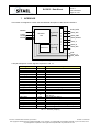
This section is assigned to contain the final detailed description of the RCCIPC interface.
RCCIPC
HOSI_REQ
NodeID
Cfg_area itf
CanTx
CanRx
Bussel
RCCIPC
core
AOs_area itf
A
r
b
i
t
e
r
HOSI_WR
HOSI_GNT
HOSI_READY
HOSI_A
HOSI_Q
HOSI_OEn
AOs Area
IRQ
Synch_rx
Bus_switch
Fig. 7-1: CANOpen slave node.
A simple description of each signal is reported in Tab. 7-1.
Clk
Rst_n
Signals
Dir
In
In
System clock
System reset
NodeId[6:0]
In
RCCIPC Node ID
Out
Out
In
Can Bus selection
Can tx line
Can rx line
BusSel
CanTx
CanRx
Description
HOSI_A[12:0]
HOSI_WR
HOSI_REQ
HOSI_Q[31:0]
HOSI_OEn
In
In
In
In-Out
HOSI_GNT
HOSI_READY
Out
Out
Address Bus
Data write or read(neg) command
Bus ownership request
Data Read Bus
Output Enable. Q contains data read when
OEn is low.
Bus ownership grant
Operation done flag
IRQ[1:0]
Synch_rx
Bus_switch
Out
Out
Out
Interrupt lines. It includes IRQ error lines
Strobe to signal synch message reception
Strobe to signal CAN bus switch condition
In
Tab. 7-1: RCCIPC periphery.
File name: CAS-RCCIPC-DTS-0001_Issue6.docx
RCCIPC - Data Sheet
The copyright of this document is vested in SITAEL S.p.A.. However, no responsibility is assumed by SITAEL S.p.A. for its use, nor for
any infringements of patents or other rights of third parties that may result from its use.
Doc.: CAS-RCCIPC-DTS-0001
Issue: 6
RCCIPC - Data Sheet
Date: 08/05/2014
Page: 25 of 53
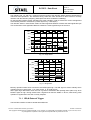
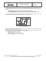
The following Fig. 7-2 and Fig. 7-3 figures show the timing of the RCCIPC arbiter interface signals during
read and write operations. The interface timing charts are here described to allow users to correctly
interface with the RCCIPC periphery (HOSI prefix has been omitted for readability).
On the RCCIPC interface all the operations are word oriented in order to assure the correct management
of the EDAC protection mechanism (1 EDAC byte every 4 data bytes).
The RCCIPC works in Little Endian mode: the least significant address contains the least significant byte
of a word and the most significant address contains the most significant byte of the word.
CLK
REQ
WR
GNT
A[n]
A
OEn
Q[n]
Q
READY
Fig. 7-2: Single Read.
CLK
REQ
WR_RDn
GNT
A[n]
A
OEn
D[n]
Q
READY
Fig. 7-3: Single write.
Memory operation starts when Host device set REQ signal high. The WR signal is used to identify which
operation has to be performed: ‘1’ for write access, ‘0’ for read access.
GNT signal high determines when the bus is granted. Afterwards data passing takes place only when
READY signal is high. During read access it signals that data are stable on Q bus, while during write
operation it signals that D bus has correctly sampled.
7.1.1 IRQ & External Trigger
The RCCIPC interface is able to handle three IRQ lines:
File name: CAS-RCCIPC-DTS-0001_Issue6.docx
RCCIPC - Data Sheet
The copyright of this document is vested in SITAEL S.p.A.. However, no responsibility is assumed by SITAEL S.p.A. for its use, nor for
any infringements of patents or other rights of third parties that may result from its use.
Doc.: CAS-RCCIPC-DTS-0001
RCCIPC - Data Sheet
Issue: 6
Date: 08/05/2014
Page: 26 of 53
•
•
IRQ[0]: Transfer IRQ (TRX_IRQ)
IRQ[1]: Error IRQ (ERR_IRQ)
The TRX_IRQ is used to signal the following conditions:
• reception of Initiate SDO transfer;
• successful elaboration of an SDO transfer;
• successful elaboration of asynchronous T/R PDO;
• NMT state transition
The ERR_IRQ line is used to inform the Host that an error has been detected.
These signals have to be cleared by user through dedicated registers described in §10.1.
Two additional lines have been used to inform the Host on reception of the Synch message and when a
bus switch event occurs. These bits are active for a single clock cycle.
7.1.2 CAN Bus Selection
The RCCIPC manages the redundancy algorithm and bus multiplexing, that is RCCIPC implements a
single CAN controller capable to handle two physical busses.
The BusSel output signal select which of the two CAN busses is logically connected to the core
according to the Redundancy algorithm.
Since the BusSel output signal is stable to ‘0’ or to ‘1’ according to the active bus selected by the
redundancy manager, it can be used as control signal for the multiplexer which “selects” the active CAN
transceiver.
7.1.3 Node-ID Acquisition and Modification
The RCCIPC acquires information on base Node-ID using a dedicated external signals (NodeID in Tab.
7-1) in the first eight clock cycles after the reset phase.
In Fig. 7-4 the behaviour of this interface is explained.
CLK
Rst_n
Node-ID
Base Node ID
Fig. 7-4: Acquisition of Node-ID information.
th
th
FPGA samples Node-ID between the 7 and 9 clock cycle after reset. Then user can re-assign
corresponding pins to different custom functions without affecting the RCCIPC functionalities.
RCCIPC utilizes this information to perform filtering function of the incoming CANopen messages and to
correctly set the COB-ID of message to be sent. In this way, the Node-ID can be modified without
requiring a new FPGA programming, but only a reset procedure in order to allow RCCIPC to re-sample
the new Node information.
7.1.4 Reset Distribution
The RCCIPC is provided of an active-low asynchronous Power-On Reset (rst_n). This reset allows
initialize all the sequential logic available in the RCCIPC in an asynchronous way.
File name: CAS-RCCIPC-DTS-0001_Issue6.docx
RCCIPC - Data Sheet
The copyright of this document is vested in SITAEL S.p.A.. However, no responsibility is assumed by SITAEL S.p.A. for its use, nor for
any infringements of patents or other rights of third parties that may result from its use.
Doc.: CAS-RCCIPC-DTS-0001
RCCIPC - Data Sheet
Issue: 6
Date: 08/05/2014
Page: 27 of 53
Together with this global reset, the RCCIPC has three additional signals that act as asynchronous reset
to re-establish the default values of RCCIPC internal registers. These signals are associated to following
conditions:
• Bus switch: the whole RCCIPC core is reset, including the CAN core;
• Reset Application: the registers defined in the Application Objects area are reset;
• Reset Communication: the registers defined in the Communication Objects area are reset.
To act as asynchronous resets these three signals are combined with the power-on reset and
synchronized using a dedicated circuit whose structure is reported in Fig. 7-5
orst_n
clk
irst_n
Fig. 7-5: Reset synchronizer.
Due to their critical functions, the user has to verify that no timing violations on these reset signals has
been arisen after the Place and Route process.
A static timing analysis has to be performed on the output signals of the second Flip-Flip of the
synchronizer circuit. Here below the paths that has to be verified:
• Bus Switch : /SW_RST/rst_n/Q[0];
• Reset Application : /AO_RST/rst_n/Q[0];
• Reset Communication: /COM_RST/rst_n/Q[0]
File name: CAS-RCCIPC-DTS-0001_Issue6.docx
RCCIPC - Data Sheet
The copyright of this document is vested in SITAEL S.p.A.. However, no responsibility is assumed by SITAEL S.p.A. for its use, nor for
any infringements of patents or other rights of third parties that may result from its use.
Doc.: CAS-RCCIPC-DTS-0001
RCCIPC - Data Sheet
Issue: 6
Date: 08/05/2014
Page: 28 of 53
8
SIMULATION ENVIRONMENT
This section gives the instructions to set-up and run simulation of the RCCIPC core. The simulation setup procedure is based on the “make” tool and all the tools specific commands are included in the
“Makefile” script.
Compilation/analysis and elaboration command for the VHDL files are defined as the VHDL_Com/Elab
Variables:
•
$(VHDL_Com) – VHDL compilation command
•
$(VHDL_Elab) – Elaboration command
W = worklib
#
- VHDL compilation command
VHDL_Comp = ncvhdl -V93 -WORK
#
- elaboration command
VHDL_Elab = ncelab
-ACCESS +rw
The $(W) variable indicates the output directory for compiled files and tags.
The “setup” command section is assigned to build the tool specific Set-up environment. The following box
shows the example of the Cadence NCsim simulator, which requires the cds.lib, hdl.var to link “worklib””
and “standard” libraries.
setup:
mkdir ./worklib
mkdir ./axcelerator
echo ‘DEFINE worklib ./worklib’
> cds.lib
echo ‘DEFINE ieee $(CDS_ROOT)/tools/inca/files/IEEE’ >> cds.lib
echo ‘DEFINE std $(CDS_ROOT)/tools/inca/files/STD’
>> cds.lib
echo ‘DEFINE synopsys $(CDS_ROOT)/tools/inca/files/SYNOPSYS’ >> cds.lib
echo ‘DEFINE LIB_MAP (.=> worklib, + => worklib )’
> hdl.var
echo ‘DEFINE WORK worklib’
>> hdl.var
echo ‘`timescale 1ns/10ps’
> time.v
Relationships between the design sub-module is explicitly indicated in the dependency section of the
Makefile. For example the notation of the following Box indicates that test-bench VHDL entity
RCCIPC_tb (Top of simulation hierarchy) depends on the RCCIPC.vhdl and parser.vhd. Module that have
to be analysed before it.
$(W)/RCCIPC_tb.vhmdl : \
$(W)/RCCIPC.vhmdl \
$(W)/parser.vhmdl
When a new design is developed on the RCCIPC core these Makefile lines have to be edited to insert the
new custom hierarchy.
A specific file (Makefile.mem) is included in the Makefile and called during the compilation process
defining which technology model has to be applied for RCCIPC simulation.
File name: CAS-RCCIPC-DTS-0001_Issue6.docx
RCCIPC - Data Sheet
The copyright of this document is vested in SITAEL S.p.A.. However, no responsibility is assumed by SITAEL S.p.A. for its use, nor for
any infringements of patents or other rights of third parties that may result from its use.
Doc.: CAS-RCCIPC-DTS-0001
RCCIPC - Data Sheet
Issue: 6
Date: 08/05/2014
Page: 29 of 53
M0
M1
M2
= RCCIPC_DB/SRC
= $(M0)/LIBRARIES
= $(M1)/TECH_GEN
MPATH = .:$(M0):$(M1):$(M2)
$(W)/mem_tech.vhmdl : \
$(W)/CCIPCconf.vhmdl \
$(W)/tech_generic.vhmdl
This Makefile includes only the instruction to compile the Generic technology model. User has to add all
the files and their dependencies needed to compile and simulate with the specific technology.
NCSIM tool example
The simple steps to set-up a new simulation directory and start simulating RCCIPC with the Cadence
Ncsim tool are explained in this example.
Start creating the new (YourSIM) simulation directory:
>mkdir YourSIM
>cd YourSIM
Create a symbolic link to the main directory of CCIPC DataBase directory with CCIPC_DB name:
ln –s /YourPath/RCCIPC_DB RCCIPC_DB
Create a symbolic link to the to the Makefile included in the SRC directory:
>ln -s RCCIPC_DB/SRC/Makefile .
>ln -s RCCIPC_DB/SRC/Makefile.mem
.
Set-up the simulator path in the $CDS_ROOT environment variable
>setenv CDS_ROOT YOUR_SIMULATOR_PATH
Launch the set-up command
> make setup
Create the following simulation auxiliary file:
> touch stimuli.txt
Now, launch the make command to generate simulation file:
> make
After process elaboration, to simulate the system launch the following command:
> ncsim RCCIPC_tb:A –gui &
File name: CAS-RCCIPC-DTS-0001_Issue6.docx
RCCIPC - Data Sheet
The copyright of this document is vested in SITAEL S.p.A.. However, no responsibility is assumed by SITAEL S.p.A. for its use, nor for
any infringements of patents or other rights of third parties that may result from its use.
Doc.: CAS-RCCIPC-DTS-0001
RCCIPC - Data Sheet
Issue: 6
Date: 08/05/2014
Page: 30 of 53
Other tools
If another tool is utilised, the $(VHDL_Comp), and $(CHDL_Elab) variables and the tool Set-up section
have to be modified inserting the specific tool commands before proceeding with the compilation process.
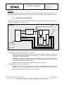
8.1 RCCIPC Core Test-Bench
The RCCIPC core test-bench that has been used to test the CANopen functionalities supported by the
RCCIPC slave node is presented in Fig. 8-1.
RCCIPC_tb
Dump
CAN bus
CAN MST
CAN irq
UUT
CAN
itf
Parser
Memory bus
RCCIPC
Core
&
AOs
Arbiter
Memory req/gnt
Stimuli
Fig. 8-1: RCCIPC test-bench.
The test-bench module (called RCCIPC_tb) consists of:
Parser module: it traduces input stream from Stimuli file in specific requests on CAN MST or
UUT Memory interface emulating the external device. It controls CAN MST and emulates
host device in the simulation test
CAN MST: it implements a CAN controller module based on micro-controller interface that
allows exchanging CAN data frame with the UUT. This module works with an input frequency
of 16MHz and with 1Mbps of CAN bit rate
UUT: it is the Unit under test and it implements the RCCIPC slave node.
The files used during the test procedure are:
Stimuli: it contains the test instruction used to drive the CAN-MST interface and also to
perform access on AOs module emulating the behaviour of a generic external device interface
Test Log: this task logs any transition on UUT interface.
File name: CAS-RCCIPC-DTS-0001_Issue6.docx
RCCIPC - Data Sheet
The copyright of this document is vested in SITAEL S.p.A.. However, no responsibility is assumed by SITAEL S.p.A. for its use, nor for
any infringements of patents or other rights of third parties that may result from its use.
Doc.: CAS-RCCIPC-DTS-0001
RCCIPC - Data Sheet
Issue: 6
Date: 08/05/2014
Page: 31 of 53
8.2 Input Stimuli Format
The input stimuli for the CANOpen testbench are built as sequence of CAN messages and memory
accesses on its host interface. Both of them are written in the .in test files using the intuitive format
described below in Tab. 8-1.
Function
can read_msg
can clear_irq
can set_irq
start_node $NodeID
stop_node $NodeID
rst_comm $NodeID
rst_node $NodeID
enter_preop $NodeID
Description
CAN master read message received (*)
CAN master clear message received IRQ (**)
CAN master enable message received IRQ (***)
CAN Master send a “Enter Operational state” request to $NodeID
CAN Master send a “Stop Node” request to $NodeID
CAN Master send a “Reset Communication” request to $NodeID
CAN Master send a “Reset Application” request to $NodeID
CAN Master send a “Enter Pre-Operational state” request to $NodeID
Heartbeat $NodeID
CAN master send an Heartbeat message.
$NodeID = Master Node ID
CAN Master send synch object
CAN Master send RPDO message
$COB-ID – RPDO COB-ID
$DATA – RPDO data [max 8 byte]
CAN Master sends SDO request:
$ID – ID of SDO client
$TYPE – SDO type:
• BlkIDL $Index $subIndex $size
o $Index – Pointed index
o $subIndex – pointed sub-index
o $size –Block download size
• BlkDL $cflag $byte_num
o $cflag – status of completed bit
o $byte_num – number of bytes to download
• BlkEndDW
• BlkIUL $Index $subIndex $Blksize
o $Index – Pointed index
o $subIndex – pointed sub-index
o $Blksize – Block size
• BlkUL $ackseq $Blksize
o $ackseq – Sequence number of last segment rx
o $Blksize – Next Block size
• EndBlkUL
• Abort $Index $subIndex $abort_code
o $Index – Pointed index
o $subIndex – pointed sub-index
o $abort_code – transmitted abort code
synch
rpdo $COBID $DATA
sdo $ID $TYPE $OPT
Waitsegm $num_seg
Fillbuf $ADDRESS $len
Trig $TPDO_NUM
Waitirq $IRQ_TYPE
CAN master wait for $num_seq RCCIPC SDO messages during the
SDO block upload service
Host device fills $len consecutive SRAM locations with static data
starting from $Address
Host Device requests the transmission of the $TPDO_NUM TPDO.
Wait for a specific IRQ.
File name: CAS-RCCIPC-DTS-0001_Issue6.docx
RCCIPC - Data Sheet
The copyright of this document is vested in SITAEL S.p.A.. However, no responsibility is assumed by SITAEL S.p.A. for its use, nor for
any infringements of patents or other rights of third parties that may result from its use.
Doc.: CAS-RCCIPC-DTS-0001
RCCIPC - Data Sheet
Issue: 6
Date: 08/05/2014
Page: 32 of 53
Function
Description
$IRQ_TYPE:
• Canmsg – CAN master waits rx message IRQ
• Error – Host device waits RCCIPC error IRQ
• Pdo – Host device waits the end of PDO processing
• Sdo – Host device waits the end of SDO processing
• Synch_rx – Host device waits synch object reception flag
• Bus_switch – Host device waits bus switch flag
Host device reads $len word starting from $Address
Host device write data word at specific $Address
Parser module waits for $time us before reading next instruction
Dev read $Address $len
Dev write $Address $data
Waitus $time
Tab. 8-1: Stimuli instruction definition.
(*) The read_msg function returns ID, Data and length of CAN message received. and it is composed of
the following command:
READ
READ
READ
READ
READ
READ
READ
READ
READ
READ
READ
READ
READ
CAN
CAN
CAN
CAN
CAN
CAN
CAN
CAN
CAN
CAN
CAN
CAN
CAN
00000020: read RX_ARB_0 register
00000021: read RX_ARB_1 register
00000022: read RX_ARB_2 register
00000023: read RX_ARB_3 register
00000024: read RX_MSG_0 register
00000025: read RX_MSG_1 register
00000026: read RX_MSG_2 register
00000027: read RX_MSG_3 register
00000028: read RX_MSG_4 register
00000029: read RX_MSG_5 register
0000002A: read RX_MSG_6 register
0000002B: read RX_MSG_7 register
0000002C: read RX_STATUS register
The table below explains functions of the CAN MST receiver interface registers:
Name
RX_ARB_0
RX_ARB_1
RX_ARB_2
RX_ARB_3
RX_MSG_0
RX_MSG_1
RX_MSG_2
RX_MSG_3
RX_MSG_4
RX_MSG_5
RX_MSG_6
RX_MSG_7
RX_STATUS
Address(Hex)
00000020
00000021
00000022
00000023
00000024
00000025
00000026
00000027
00000028
00000029
0000002A
0000002B
0000002C
ID[10]
ID[2]
ID[9]
ID[1]
ID[8]
ID[0]
not used
Function[7:0]
ID[7]
ID[6]
ID[5]
ID[4]
not used=”00000”
not used
not used
st
1 Byte received
nd
2 Byte received
rd
3 Byte received
th
4 Byte received
th
5 Byte received
th
6 Byte received
th
7 Byte received
th
8 Byte received
RX_len
ID[3]
Tab. 8-2: CAN MST registers of Receiver interface.
(**) The clear_irq function allows clearing CAN message IRQ and it performs the following command:
File name: CAS-RCCIPC-DTS-0001_Issue6.docx
RCCIPC - Data Sheet
The copyright of this document is vested in SITAEL S.p.A.. However, no responsibility is assumed by SITAEL S.p.A. for its use, nor for
any infringements of patents or other rights of third parties that may result from its use.
Doc.: CAS-RCCIPC-DTS-0001
RCCIPC - Data Sheet
Issue: 6
Date: 08/05/2014
Page: 33 of 53
WRITE CAN 00000003 A0: write SETUP_3 register
where SETUP_3 register is defined below:
Name
SETUP_3
Address(Hex)
00000003
RxClear
Rst
IRQclear
Function[7:0]
-TxReq
RSJ
(***) The can_set irq function allows enabling CAN IRQ on message reception and it performs the following
command:
WRITE CAN 00000000 42: write SETUP_0 register
where SETUP_0 register is defined below:
Name
SETUP_0
Address(Hex)
00000000
BPR
--
Function[7:0]
---
--
RX-irq
--
Tab. 8-3 reports the meanings of the constants utilized in the test files:
Name
R_ST_ADDR
Value
10A4h
R_IRQ_ST_ADDR
1128h
Description
Pointer to HurriCANe & RCCIPC status register (Index 2000 –
SubIndex 2)
Pointer to IRQ status register (Index 2000 – SubIndex 4)
R_IRQ_MK_CL_ADDR
112Ch
Pointer to IRQ mask-clear register (Index 2000 – SubIndex 5)
Tab. 8-3: Test Constant value.
8.3 Output Test Log File
The RCCIPC test-bench furnishes a simulation output Log file (report.txt) that reports all the traffic
recorded on CAN bus and the memory accesses performed by Host interface. The Log file helps user
during the debug phase to understand what data are effectively exchanged between CAN Master, HOST
and RCCIPC.
The following information are reported in the Log File:
1. Time stamp : time reference expressed in ns;
2. Access Type : this field reports the type of operation to be executed:
a. READ : read operation;
b. WRITE : write operation.
3. Peripheral : this field defines which peripheral performs the operation:
a. CAN : CAN Master;
b. EXT : Host interface;
4. Address : Operation Address. The address refers to CAN Master internal registers when
Peripheral field is CAN, while it refers to RCCIPC Configuration Area or RAM area when
Peripheral field is set to EXT;
5. Data : Data read or write according to Access type.
An example of Log File, without time stamp information, is reported in next table with a simple description
of the operations performed:
File name: CAS-RCCIPC-DTS-0001_Issue6.docx
RCCIPC - Data Sheet
The copyright of this document is vested in SITAEL S.p.A.. However, no responsibility is assumed by SITAEL S.p.A. for its use, nor for
any infringements of patents or other rights of third parties that may result from its use.
Doc.: CAS-RCCIPC-DTS-0001
Issue: 6
RCCIPC - Data Sheet
Date: 08/05/2014
Page: 34 of 53
Access
Type
WRITE
WRITE
READ
READ
READ
READ
READ
READ
READ
READ
READ
READ
READ
READ
READ
READ
READ
WRITE
READ
READ
READ
Per.
Address
Data
Description
CAN
CAN
CAN
CAN
CAN
CAN
CAN
CAN
CAN
CAN
CAN
CAN
CAN
CAN
CAN
EXT
EXT
EXT
EXT
EXT
EXT
00000000
00000003
00000020
00000021
00000022
00000023
00000024
00000025
00000026
00000027
00000028
00000029
0000002A
0000002B
0000002C
000010A4
00001128
0000112C
00001128
00000040
00000044
00000042
000000A0
000000E0
00000041
00000000
00000030
00000000
00000030
0000008D
00000078
00000000
00000000
00000000
00000000
00000001
00000810
00001000
10000000
00000000
00000802
60000120
Write CAN Master SETUP_0 register.
Write CAN Master SETUP_3 register.
Read CAN Master Arbitration registers.
(RX_ARB_0 – RX_ARB_3)
Read CAN Master Message registers.
(RX_MSG_0 – RX_MSG_7).
Read CAN Master RX_STATUS register.
HOST reads RCCIPC “HurriCANe & RCCIPC Status” register
HOST reads RCCIPC “IRQ status” register
HOST writes RCCIPC “IRQ mask-clear” register
HOST reads RCCIPC “IRQ status” register
HOST reads RCCIPC AO memory
Tab. 8-4: Log File example and explanation.
Because the time stamp value could vary depending on simulator used, could be useful having a Log file
without time stamp information. The following command creates a Log file (report_val.txt) without time
information:
> cat report.txt
report_val.txt
|
awk
'{printf
"%-5s
%s
%s
%s
\n",$3,$4,$5,$6}'
>
8.4 Test Procedures Simulation
In this paragraph, the instructions to perform the tests included in the DataBase and to define new test
procedures are described.
8.4.1 RCCIPC default tests
All the tests corresponding to the RCCIPC test procedure can be easily executed exploiting the
RCCIPC_test.sh shell-script.
The RCCIPC_test script executes the following steps:
• Generates specific test configuration file
• Compiles the new VHDL testbench
• Launches the simulation scripts
At the end of simulation, it automatically checks if the test is correctly passed comparing the produced
output file with the correspondent reference output file
To perform the tests reported in Tab. 5-6, enter in your simulation directory
File name: CAS-RCCIPC-DTS-0001_Issue6.docx
RCCIPC - Data Sheet
The copyright of this document is vested in SITAEL S.p.A.. However, no responsibility is assumed by SITAEL S.p.A. for its use, nor for
any infringements of patents or other rights of third parties that may result from its use.
Doc.: CAS-RCCIPC-DTS-0001
RCCIPC - Data Sheet
Issue: 6
Date: 08/05/2014
Page: 35 of 53
> cd YourSIM
Create a symbolic link to the RCCIPC_test shell script:
> ln -s RCCIPC_DB/SIM_SCRIPT/RCCIPC_test.sh
> ln -s RCCIPC_DB/SIM_SCRIPT/RCCIPCTestWriter.pl
To run tests included in VRP_TB directory and reported in Tab. 5-6 launch the RCCIPC_test.sh
command specifying the test name.
> ./RCCIPC_test.sh –name TP5113_boot
To run tests included in ADDON_TB directory launch the RCCIPC_test.sh command specifying the path
pointing the test.
>./RCCIPC_test.sh –dir RCCIPC_DB/SIM_SCRIPT/ADDON_TB/TP5123/AutoOperational/S1
The whole list of ADDON_TB tests is reported in the README.txt file available in the main RCCIPC
DataBase directory.
At the end of simulation, if the test is passed the following messages appears:
> Simulation success: files match
Otherwise, the test returns:
> Simulation failure: files differ
8.4.2 User defined tests
To create a new test procedure, generate the specific test file (MYFILE.in) using the instructions defined
in Tab. 8-1.
Using the RCCIPCTestWriter.pl script, compile the MYFILE.in test and redirect the output to the stimuli.txt
file contained in the MYSIM directory.
> ./RCCIPCTestWriter.pl MYFILE.in > YourSIM/stimuli.txt
Now launch the simulation.
> ncsim RCCIPC_tb:A –gui
File name: CAS-RCCIPC-DTS-0001_Issue6.docx
RCCIPC - Data Sheet
The copyright of this document is vested in SITAEL S.p.A.. However, no responsibility is assumed by SITAEL S.p.A. for its use, nor for
any infringements of patents or other rights of third parties that may result from its use.
Doc.: CAS-RCCIPC-DTS-0001
RCCIPC - Data Sheet
Issue: 6
Date: 08/05/2014
Page: 36 of 53
9
SYNTHESIS AND FITTING SCRIPTS
Synthesis and fitting scripts are included in the SYN_SCRIPT and FIT_SCRIPT directories.
Follow the simple instructions included in next sub-sections for each technology.
The constraint file (RCCIPC.sdc), included in the SYN_SCRIPT directory, keeps the system clock and
peripheral timing constraints for the RCCIPC design and it is used during synthesis process.
Before proceeding with Synthesis and Fitting processes assure that all files needed to instantiate memory
module for the selected technology have been correctly generated and copied in the correspondent
directory (see §5.2.1).
9.1 Microsemi (RT)AX FPGA
9.1.1 Synthesis
Go to SYN_SCRIPT directory and open the RCCIPC.prj file using the Synplify Pro Microsemi Edition tool.
Fig. 9-1: Microsemi synthesis tool.
File name: CAS-RCCIPC-DTS-0001_Issue6.docx
RCCIPC - Data Sheet
The copyright of this document is vested in SITAEL S.p.A.. However, no responsibility is assumed by SITAEL S.p.A. for its use, nor for
any infringements of patents or other rights of third parties that may result from its use.
Doc.: CAS-RCCIPC-DTS-0001
RCCIPC - Data Sheet
Issue: 6
Date: 08/05/2014
Page: 37 of 53
If necessary, use the Implementation Option menu (on the left edge) to synthesis option:
• Device selection: choose target FPGA
• Options: change synthesis option
• Constraint: add constraint files
• Implementation results: change synthesis output file destination
• VHDL: set VHDL options
After configuration phase, start the synthesis process clicking on Run button in the left-top side of the
window.
The Synthesis process generates, in the specified output directory, the RCCIPC.edn file.
9.1.2 Fitting
When the synthesis process is completed, in the FIT_SCRIPT directory, open the RCCIPC.adb file using
the Microsemi Designer tool.
Fig. 9-2: Microsemi fitting tool.
Utilize the Options->Device Selection menu (on the left edge) to change the Device, speed grade,
package etc. selections if needed.
Click on the “Programming File” button to start the fitting process.
The fitting process completes with generation of the RCCIPC.pdb FPGA programming file.
File name: CAS-RCCIPC-DTS-0001_Issue6.docx
RCCIPC - Data Sheet
The copyright of this document is vested in SITAEL S.p.A.. However, no responsibility is assumed by SITAEL S.p.A. for its use, nor for
any infringements of patents or other rights of third parties that may result from its use.
Doc.: CAS-RCCIPC-DTS-0001
Issue: 6
RCCIPC - Data Sheet
Date: 08/05/2014
Page: 38 of 53
10 RCCIPC MEMORY MAPPING
The RCCIPC utilizes two different memory areas:
•
•
Configuration & Status area: this is implemented in sparse registers assigned to control the
main parameters inside the Core.
Application Objects area: this area includes the application objects shared between the
RCCIPC and host device
10.1 Configuration & Status Area
The RCCIPC Configuration & Status area is composed of the following OD entries.
Index
2000h
SubIndex
Register Name
0h
Redundancy
Management
Bdefault
Ttoggle
Ntoggle
Ctoggle
Node
parameters
ID base
RCCIPC status
& configuration
HurriCANe
configuration
HurriCANe
&
RCCIPC status
IRQ status
IRQ mask-clear
EDAC error
TPDO Trig
1h
2h
3h
4h
0h
2002h
1h
0h
1h
2003h
2h
3h
4h
5h
6h
Cfg
Address
0x1040
U8
0x1044
0x1048
0x104C
0x1050
0x1094
U8
U8
U8
U8
U8
0x1098
0x109C
U8
U8
0x10A0
U32
0x10A4
U32
0x1128
0x112C
0x1130
0x1134
U32
U32
U32
U32
Obj Type
Tab. 10-1: Configuration Register mapping.
Each register is defined in next tables. Each table is composed of the following fields:
• field: it associates a mnemonic name to register field;
• sdo: it indicates the access type supported via SDO;
• host: it indicated how Host can access to the register;
• rst: it indicates the reset value of the field. The following notation is used:
o Binary: single(‘) or double(“) quotes indicate binary values;
o Hexadecimal: 0xnn notation indicates an Hexadecimal number;
o RST_VAL: the reset value is indicated in the correspondent parameter available in the
CCIPC configuration file (CCIPCconf.vhd).
Three different access types are defined:
• ro – Read Only;
• rw – Read Write;
File name: CAS-RCCIPC-DTS-0001_Issue6.docx
RCCIPC - Data Sheet
The copyright of this document is vested in SITAEL S.p.A.. However, no responsibility is assumed by SITAEL S.p.A. for its use, nor for
any infringements of patents or other rights of third parties that may result from its use.
Doc.: CAS-RCCIPC-DTS-0001
RCCIPC - Data Sheet
Issue: 6
Date: 08/05/2014
Page: 39 of 53
•
field
sdo
host
rst
rc - Read and clean. A write access only cleans the value of the register.
Redundancy Management : Index 2000h - Sub-Index 0h - Address 0x1040
31 30 29 28 27 26 25 24 23 22 21 20 19 18 17 16 15 14 13 12 11 10 9 8 7 6 5 4 3 2 1 0
reserved
brm_s0
--ro
ro
0x000000
0x4
Bit Number
7..0
Mnemonic
brm _s0
Description
SubIndex-0 of Bus Redundancy management entry
b_def
Bdefault: Index 2000h - Sub-Index 1h - Address 0x1044
31 30 29 28 27 26 25 24 23 22 21 20 19 18 17 16 15 14 13 12 11 10 9 8 7 6 5 4 3 2 1 0
reserved
reserved
field
sdo
host
rst
-ro
0x0
Bit Number
1
field
sdo
host
rst
Mnemonic
t_toggle
Description
Ttoggle value
Ntoggle: Index 2000h - Sub-Index 3h - Address 0x104C
31 30 29 28 27 26 25 24 23 22 21 20 19 18 17 16 15 14 13 12 11 10 9 8 7 6 5 4 3 2 1 0
reserved
n_toggle
--ro
ro
N_TOGGLE
0x0
Bit Number
3..0
field
sdo
host
rst
Description
Default CAN Bus
Ttoggle: Index 2000h - Sub-Index 2h - Address 0x1048
31 30 29 28 27 26 25 24 23 22 21 20 19 18 17 16 15 14 13 12 11 10 9 8 7 6 5 4 3 2 1 0
reserved
t_toggle
--ro
ro
T_TOGGLE
0x0
Bit Number
3..0
field
sdo
host
rst
Mnemonic
b_def
-ro
B_DEF
Mnemonic
n_toggle
Description
Ntoggle value
Ctoggle: Index 2000h - Sub-Index 4h - Address 0x1050
31 30 29 28 27 26 25 24 23 22 21 20 19 18 17 16 15 14 13 12 11 10 9 8 7 6 5 4 3 2 1 0
reserved
c_toggle
--ro
ro
0x0
0x00
File name: CAS-RCCIPC-DTS-0001_Issue6.docx
RCCIPC - Data Sheet
The copyright of this document is vested in SITAEL S.p.A.. However, no responsibility is assumed by SITAEL S.p.A. for its use, nor for
any infringements of patents or other rights of third parties that may result from its use.
Doc.: CAS-RCCIPC-DTS-0001
Issue: 6
RCCIPC - Data Sheet
Date: 08/05/2014
Page: 40 of 53
Bit Number
7..0
field
sdo
host
rst
Description
SubIndex-0 of Node Parameters entry
Mnemonic
node_id
Description
RCCIPC Node-ID value sampled from external dedicated pins
RCCIPC Status & Configuration : Index 2003h - Sub-Index 0h - Address 0x109C
31 30 29 28 27 26 25 24 23 22 21 20 19 18 17 16 15 14 13 12 11 10 9 8 7 6 5 4 3 2 1 0
reserved
st&cfg_s0
--ro
ro
0x000000
0x6
Bit Number
7..0
Mnemonic
st&cfg
Description
SubIndex-0 of RCCIPC Status and Configuration entry
HurriCANe configuration: Index 2003h - Sub-Index 1h - Address 0x10A0
31 30 29 28 27 26 25 24 23 22 21 20 19 18 17 16 15 14 13 12 11 10 9 8 7 6 5 4 3 2 1 0
reserved
RSJ
PS2
PS1
BPR
can_rst
field
Mnemonic
Nodepar_s0
ID Base: Index 2002h - Sub-Index 1h - Address 0x1098
31 30 29 28 27 26 25 24 23 22 21 20 19 18 17 16 15 14 13 12 11 10 9 8 7 6 5 4 3 2 1 0
reserved
node_id
--ro
ro
0x0
0x00
Bit Number
7..0
field
sdo
host
rst
Description
Ctoggle value
Node Parameters : Index 2002h - Sub-Index 0h - Address 0x1094
31 30 29 28 27 26 25 24 23 22 21 20 19 18 17 16 15 14 13 12 11 10 9 8 7 6 5 4 3 2 1 0
reserved
Nodepar_s0
--ro
ro
0x000000
0x1
Bit Number
7..0
field
sdo
host
rst
Mnemonic
c_toggle
Mnemonic
BPR
PS1
PS2
File name: CAS-RCCIPC-DTS-0001_Issue6.docx
-rw
-rw
-rw
-rw
-rw
‘1’
PS2_VAL
PS1_VAL
BPR_VAL
Bit Number
1..0
5..2
9..6
-ro
0x0
RSJ_VAL
sdo
host
rst
Description
Frequency scaler value
Phase Segment 1 value
Phase Segment 2 value
RCCIPC - Data Sheet
The copyright of this document is vested in SITAEL S.p.A.. However, no responsibility is assumed by SITAEL S.p.A. for its use, nor for
any infringements of patents or other rights of third parties that may result from its use.
Doc.: CAS-RCCIPC-DTS-0001
Issue: 6
RCCIPC - Data Sheet
Date: 08/05/2014
Page: 41 of 53
Bit Number
12..10
13
Description
Resynchronization Jump width
Active High CAN Core reset
HurriCANe & RCCIPC status: Index 2003h - Sub-Index 2h - Address 0x10A4
31 30 29 28 27 26 25 24 23 22 21 20 19 18 17 16 15 14 13 12 11 10 9 8 7 6 5 4 3 2 1 0
tx_err_cnt
rx_err_cnt
reserved
rccipc_state
active_bus
rx_overflow
reserved
err_passive
bus_off
auto_op
field
Mnemonic
RSJ
can_rst
-ro
0x0
Bit Number
5..0
Mnemonic
ccipc_state
6
7
active_bus
rx_overflow
9
10
11
err_passive
bus_off
auto_op
23..16
31..24
rx_err_cnt
tx_err_cnt
-ro
0x0
-ro
0x0
-- -- -- -- -- -ro ro ro ro rw ro
‘0’ ‘0’ ‘0’ ‘0’ ‘0’
-ro
“000000”
AUTO_OPER
sdo
host
rst
Description
RCCIPC NMT state value:
• 000001
Initialising
• 000010
Reset Application
• 000100
Reset Communication
• 001000
Pre-Operational
• 010000
Operational
• 100000
Stopped
Currently CAN bus used
This condition arises when incoming message arrives and the
previous message has not been still processed.
This condition is handle as a CAN interface error and is
associated to Error IRQ line.
User has to clear this bit during the IRQ handling.
CAN core Error Passive condition.
CAN core Bus Off condition.
This fag indicates if the Auto-operational condition is activated or
not.
If ‘1’ RCCIPC automatically enters in Operational state after
Initialization phase.
CAN core Receiver error counter value.
CAN core Transmitter error counter value.
IRQ status: Index 2003h - Sub-Index 3h - Address 0x1128
31 30 29 28 27 26 25 24 23 22 21 20 19 18 17 16 15 14 13 12 11 10 9 8 7 6 5 4 3 2 1 0
File name: CAS-RCCIPC-DTS-0001_Issue6.docx
reserved
pdo_rx
pdo_tx
end_sdo
sdo_abort
reserved
sdo_dw
sdo_up
init_sdo
nmt_cos
reseved
edac_err
can_err
field
RCCIPC - Data Sheet
The copyright of this document is vested in SITAEL S.p.A.. However, no responsibility is assumed by SITAEL S.p.A. for its use, nor for
any infringements of patents or other rights of third parties that may result from its use.
Doc.: CAS-RCCIPC-DTS-0001
Issue: 6
RCCIPC - Data Sheet
Date: 08/05/2014
Page: 42 of 53
sdo
host
rst
31 30 29 28 27 26 25 24 23 22 21 20 19 18 17 16 15 14 13
--- -- --ro ro ro
0x0000
‘0’ ‘0’ ‘0’
Bit
Number
0
1
2
3
9
10
11
12
14
15
12
-ro
‘0’
11
-ro
‘0’
10
-ro
‘0’
9 8 7 6 5 4 3 2 1
---- -- -ro
ro
ro ro ro
‘0’
“00000”
‘0’ ‘0’ ‘0’
0
-ro
‘0’
Mnemonic
Description
IRQ line
pdo_rx
pdo_tx
end_sdo
sdo_abort
sdo_dw
sdo_up
init_sdo
nmt_cos
edac_err
can_err
RPDO successfully processed
TPDO successfully processed
SDO successfully completed
SDO abort detected
Download SDO type
Upload SDO type
Initiate SDO request accepted.
RCCIPC change of state.
EDAC error flag.
Error on CAN interface.
TRX_IRQ
TRX_IRQ
TRX_IRQ
ERR_IRQ
----TRX_IRQ
TRX_IRQ
ERR_IRQ
ERR_IRQ
The following register allows masking and clearing different CCIPC IRQ. The following notation is used to
mask and unmask IRQ:
• ‘0’ – not masked. IRQ propagated
• ‘1’ – masked. IRQ not propagated.
IRQ Mask-clear: Index 2003h - Sub-Index 4h - Address 0x112C
31 30 29 28 27 26 25 24 23 22 21 20 19 18 17 16 15 14 13 12 11 10 9 8 7 6 5 4 3 2 1 0
Bit Number
0
1
2
3
11
12
14
15
16
17
18
19
-ro
“0000000”
Mnemonic
pdo_rx_mask
pdo_tx_mask
end_sdo_mask
sdo_abort_mask
init_sdo_mask
nmt_cos_mask
edac_err_mask
can_err_mask
pdo_rx_clear
pdo_tx_clear
end_sdo_clear
sdo_abort_clear
File name: CAS-RCCIPC-DTS-0001_Issue6.docx
-- -- -- -- -- -- -- -- -rw rw rw rw rw rw ro rw rw
‘0’ ‘0’ ‘0’ ‘0’ ‘0’ ‘0’ ‘0’ ‘0’ ‘0’
reserved
-ro
“0000000”
pdo_rx_mask
pdo_tx_mask
end_sdo_mask
sdo_abort_mask
-- -- -- -- -rw rw rw rw rw
‘0’ ‘0’ ‘0’ ‘0’ ‘0’
reserved
init_sdo_mask
nmt_cos_mask
reserved
edac_err_mask
can_err_mask
pdo_rx_clear
pdo_tx_clear
end_sdo_clear
sdo_abort_clear
init_sdo_clear
nmt_cos_clear
sdo
host
rst
edac_err_clear
can_err_clear
field
-- -- -- -rw rw rw rw
‘0’ ‘0’ ‘0’ ‘0’
Description
Mask RPDO successfully processed IRQ.
Mask TPDO successfully processed IRQ.
Mask SDO successfully completed IRQ.
Mask SDO abort detected IRQ.
Mask Initiate SDO request accepted IRQ.
Mask RCCIPC change of state IRQ.
Mask EDAC error flag IRQ.
Mask Error on CAN interface IRQ.
Clear RPDO successfully processed IRQ.
Clear TPDO successfully processed IRQ.
Clear SDO successfully completed IRQ.
Clear SDO abort detected IRQ.
RCCIPC - Data Sheet
The copyright of this document is vested in SITAEL S.p.A.. However, no responsibility is assumed by SITAEL S.p.A. for its use, nor for
any infringements of patents or other rights of third parties that may result from its use.
Doc.: CAS-RCCIPC-DTS-0001
Issue: 6
RCCIPC - Data Sheet
Date: 08/05/2014
Page: 43 of 53
Bit Number
27
28
30
31
Description
Clear Initiate SDO request accepted IRQ.
Clear RCCIPC change of state IRQ.
Clear EDAC error flag IRQ.
Clear Error on CAN interface IRQ.
EDAC error: Index 2003h - Sub-Index 5h - Address 0x1130
31 30 29 28 27 26 25 24 23 22 21 20 19 18 17 16 15 14 13 12 11 10 9 8 7 6 5 4 3 2 1 0
reserved
serr
derr
edac_en
field
Mnemonic
init_sdo_clear
nmt_cos_clear
edac_err_clear
can_err_clear
reserved
sdo
host
rst
-ro
“000000000000000000000”
Bit Number
8
Mnemonic
serr
9
derr
10
edac_en
-- -- -rw rc rc
‘0’ ‘0’ ‘0’
-ro
0x00
Description
Single error flag.
This bit is auto cleared every time this register is written.
Double error flag.
This bit is auto cleared every time this register is written.
Enable EDAC capability on RCCIPC
The EDAC capability is disabled at start-up. User has to enable it after RCCIPC initialization.
Since Double error detection represents a critical condition for the core because the management of
wrong values can compromise the RCCIPC behaviour, it is strictly recommended that user reset the
RCCIPC core if this error occurs.
field
sdo
host
rst
TPDO Trig : Index 2003h - Sub-Index 6h - Address 0x1134
31 30 29 28 27 26 25 24 23 22 21 20 19 18 17 16 15 14 13 12 11 10 9 8 7 6 5 4 3 2 1 0
tpdo_trig
-wo
0x0
Bit Number
31..0
Mnemonic
tpdo_trig
Description
A write operation on this register enables the transmission of the
asynchronous TPDO.
The following table shows which events cause the inizialization of the registers:
Event
Register
Redundacy
Management
Bdefault
Ttoggle
Ntoogle
C_toggle
Node Parameters
ID Base
RCCIPC status &
Field
Note
Power-On
Reset
Application
Reset
Communication
Bus Switch
brm_s0
--
--
--
--
Constant value
b_def
t_toggle
n_toggle
c_toggle
nodepar_s0
node_id
st&cfg_s0
y
y
y
--y
--
y
y
y
--n
--
n
n
n
--n
--
n
n
n
--n
--
Constant value
Constant value
Value sampled at boot
Constant value
File name: CAS-RCCIPC-DTS-0001_Issue6.docx
RCCIPC - Data Sheet
The copyright of this document is vested in SITAEL S.p.A.. However, no responsibility is assumed by SITAEL S.p.A. for its use, nor for
any infringements of patents or other rights of third parties that may result from its use.
Doc.: CAS-RCCIPC-DTS-0001
RCCIPC - Data Sheet
Issue: 6
Date: 08/05/2014
Page: 44 of 53
Event
Register
Field
Power-On
Reset
Application
Reset
Communication
Bus Switch
y
y
y
y
y
y
y
y
y
y
-y
y
y
y
y
y
y
y
y
y
y
y
y
y
y
y
y
y
y
y
y
y
y
y
y
n
n
y
y
y
-y
y
y
y
y
y
y
y
y
y
y
y
y
y
y
n
n
y
y
y
n
n
n
n
n
n
n
n
n
n
-n
n
n
n
n
n
n
n
n
n
n
n
n
n
n
n
n
n
n
n
y
y
y
y
y
n
n
y
y
y
-y
y
y
y
y
y
y
y
y
y
y
y
y
y
y
n
n
y
y
y
Note
Configuration
HurriCANe
Configuration
HurriCANe &
RCCIPC status
IRQ status
BPR
PS1
PS2
RSJ
can_rst
ccipc_state
active_bus
rx_overflow
err_passive
bus_off
auto_op
rx_err_cnt
tx_err_cnt
pdo_rx
pdo_tx
end_sdo
sdo_abort
sdo_dw
sdo_ul
init_sdo
nmt_cos
edac_err
can_err
IRQ Mask-clear
EDAC error
TPDO Trig
serr
derr
mem_en
queue_en
serr_mask
derr_mask
tpdo_trig
Constant value
Tab. 10-2: Initialization event for Configuration and Status Area Registers.
10.1.1 IRQ handling
As already defined in §7.1.1 the RCCIPC handles two IRQ lines:
• Transfer IRQ (TRX_IRQ)
• Error IRQ (ERR_IRQ)
User has to clear the IRQ request. Three simple “pseudo-code” examples of RCCIPC IRQ manager are
written below:
TRX_IRQ
irq_status = IRQ_status_reg;
ARPDO_IRQ = irq_status[0];
ATPDO_IRQ = irq_status[1];
SDO_IRQ = irq_status[2];
INITSDO_IRQ = irq_status[11];
NMT_CS_IRQ = irq_status[12];
File name: CAS-RCCIPC-DTS-0001_Issue6.docx
## NMT change state
RCCIPC - Data Sheet
The copyright of this document is vested in SITAEL S.p.A.. However, no responsibility is assumed by SITAEL S.p.A. for its use, nor for
any infringements of patents or other rights of third parties that may result from its use.
Doc.: CAS-RCCIPC-DTS-0001
RCCIPC - Data Sheet
Issue: 6
Date: 08/05/2014
Page: 45 of 53
if (ARPDO_IRQ) {
while(elab_rpdo){
<Elaborate Data>
}
IRQ_MASK_CLEAR_reg = 0x10000;
}
if (ATPDO_IRQ) {
while(elab_tpdo){
<Elaborate Data>
}
IRQ_MASK_CLEAR_reg = 0x20000;
}
## clear RPDO part of PDO_IRQ_reg
## clear TPDO part of PDO_IRQ_reg
if (SDO_IRQ) {
<Elaborate Data>
IRQ_MASK_CLEAR_reg = 0x40000;
}
if (INITSDO_IRQ){
IRQ_MASK_CLEAR_reg = 0x8000000;
}
## clear SDO IRQ
## clear SDO IRQ
if (NMT_CS){
nmt_state = HurriCANe_&_RCCIPC_status_reg & 0x1F> ## read NMT state
IRQ_MASK_CLEAR_reg = 0x10000000;
## clear SDO IRQ
}
ERROR_IRQ
irq_status = read(IRQ_status_reg);
<Manage error>
IRQ_MASK_CLEAR_reg = ERROR_CLEAR_BIT;
## clear specific error bit
The receiver message overflow condition is associated to the HurriCANe error flag (bit 15 of IRQ status
register). Before clean the IRQ status register, user has to clear the rx_overflow error by writing the
correspondent bit of HurriCANe and RCCIPC status.
MsgIn Queue full error
irq_status = read(IRQ_status_reg);
can_err = irq_status[15];
if (can_err) {
rx_of = (read(HurriCANe&RCCIPC_status_reg)) >> 7)
if (msgin_full){
HurriCANe&RCCIPC_status_reg = 0
}
}
IRQ_MASK_CLEAR_reg = 0x8000000;
File name: CAS-RCCIPC-DTS-0001_Issue6.docx
## Overflow error
## Clear error
## clear Can error
RCCIPC - Data Sheet
The copyright of this document is vested in SITAEL S.p.A.. However, no responsibility is assumed by SITAEL S.p.A. for its use, nor for
any infringements of patents or other rights of third parties that may result from its use.
Doc.: CAS-RCCIPC-DTS-0001
RCCIPC - Data Sheet
Issue: 6
Date: 08/05/2014
Page: 46 of 53
10.2 AOs Addressing
The RCCIPC uses a single memory block of up to 512 words of 32 bits to store the Applications Objects.
The memory area is composed of the following sections, as illustrated in Fig. 10-1:
• RCCIPC private area: it contains internal RCCIPC functional registers;
• RPDO area: it stores data received by RPDO;
• RPDO area: it stores data to be transferred by TPDO;
• SDO Buffer: it stores data to be transferred by SDO;
0x7FC
Unused
0x44C
SDO Buffer
0x50
TPDO
RPDO
0x48
0x40
RCCIPC private
area
0x0
Fig. 10-1: RCCIPC Memory mapping.
In order to preserve the RCCIPC correct functionality, writing accesses on RCCIPC private area are
automatically rejected by RCCIPC.
File name: CAS-RCCIPC-DTS-0001_Issue6.docx
RCCIPC - Data Sheet
The copyright of this document is vested in SITAEL S.p.A.. However, no responsibility is assumed by SITAEL S.p.A. for its use, nor for
any infringements of patents or other rights of third parties that may result from its use.
Doc.: CAS-RCCIPC-DTS-0001
RCCIPC - Data Sheet
Issue: 6
Date: 08/05/2014
Page: 47 of 53
11 CONFIGURATION TOOL
This section explains how to configure the RCCIPC core. A simple configuration tool allows automatically
generating the VHDL configuration file that has to be copied in the SRC directory in place of the
RCCIPCconf.vhd file
11.1 VHDL Configuration File
The VHDL package configuration collects the VHDL constants used to configure the main aspects of the
RCCIPC Core like interface/technology and the default values of its configuration area objects.
The following constants are defined in the configuration file:
• TARGET_DEV: it defines the RCCIPC core target technology:
o AXCELERATOR: constant value for Microsemi Axcelerator device
o GENERIC_TECH: constant for technology independent memory model
• NODEID: RCCIPC node ID. Tthis value is used only in simulation mode. During real mode this
value is triggerd using the dedicated external pins. (Index:2002h, SubIndex:01h)
• MSTID_CONSHB: constant value of Heartbeat consumer time (index:1016h):
o MST_NODEID: it defines the Node-ID of the Master
o CONS_HB: it defines the value of the heartbeat time
• PROD_HB: constant value of Heartbeat producer time (index: 1017h)
• B_DEF: constant value of Default bus parameter (index:2000h, Sub-Index:01h)
• T_TOGGLE: constant value of Ttoggle parameter (index:2000h, Sub-Index:02h)
• N_TOGGLE: constant value of Ntoggle parameter (index:2000h, Sub-Index:03h)
• HuCANe_Cfg: default value of the HurriCANe configuration (Index:2003h, Sub-Index:01h)
o RSJ_VAL: RSJ default value
o PS2_VAL: PS2 default value
o PS1_VAL: PS1 default value
o BPR_VAL: BPR default value
• RCCIPC_ST: default value of the RCCIPC status register (Index:2003h, Sub-Index:02h
o AUTO_OP: defines the possibility of the RCCIPC to enter automatically in Operational
state at the end of the initialization phase
• SDO_BUF_TYPE : defines the characteristics of the SDO buffer
• SYS_FREQ : defined the system frequency
File name: CAS-RCCIPC-DTS-0001_Issue6.docx
RCCIPC - Data Sheet
The copyright of this document is vested in SITAEL S.p.A.. However, no responsibility is assumed by SITAEL S.p.A. for its use, nor for
any infringements of patents or other rights of third parties that may result from its use.
Doc.: CAS-RCCIPC-DTS-0001
RCCIPC - Data Sheet
Issue: 6
Date: 08/05/2014
Page: 48 of 53
11.2 RCCIPC Configuration Tool
The RCCIPC Configuration tool allows user to simply define the configuration parameters specified in the
previous paragraph.
Fig. 11-1: RCCIPC Configuration tool.
The user is in charge of defining the RCCIPC parameters and save them in the correspondent VHDL
configuration file.
File name: CAS-RCCIPC-DTS-0001_Issue6.docx
RCCIPC - Data Sheet
The copyright of this document is vested in SITAEL S.p.A.. However, no responsibility is assumed by SITAEL S.p.A. for its use, nor for
any infringements of patents or other rights of third parties that may result from its use.
Doc.: CAS-RCCIPC-DTS-0001
Issue: 6
RCCIPC - Data Sheet
Date: 08/05/2014
Page: 49 of 53
12 RCCIPC RESOURCE OCCUPATION
The results are obtained with the following RCCIPC configuration and refer to Post Place and Route
process:
• 1 Node-Id supported;
• 1 RPDOs and 1 TPDOs;
• 3 Application Objects:
o Array of U32 with 2 sub-indexes;
o Array of U32 with 2 sub-indexes;
o Array of U32 with 254 sub-indexes;
• Consumer Heartbeat Time = 5 s;
• Producer Heartbeat Time = 5 s;
• Ttoggle = 15;
• Ntoggle = 15;
For Xilinx device Combinational field refers to Number of 4 input LUTs, Sequential field refers to Number
of Slice Flip Flops and Total field refers to total number of occupied slices.
Family
Axcelerator
ProAsic
Xilinx
Device
RTAX250S
A3PE3000
XC4VLX25
Combinational
2730
4801
2250
Cells
Sequential
976
975
924
Total
3706
5776
1385
RAM
Utilization
5
5
5
87.74%
7.6%
12%
Fmax
(MHz)
16.6
19.6
27.7
Tab. 12-1: RCCIPC Area Occupation.
File name: CAS-RCCIPC-DTS-0001_Issue6.docx
RCCIPC - Data Sheet
The copyright of this document is vested in SITAEL S.p.A.. However, no responsibility is assumed by SITAEL S.p.A. for its use, nor for
any infringements of patents or other rights of third parties that may result from its use.
Doc.: CAS-RCCIPC-DTS-0001
RCCIPC - Data Sheet
Issue: 6
Date: 08/05/2014
Page: 50 of 53
13 RCCIPC TIMING CHARACTERISTICS
The RCCIPC timings characterization is reported in next tables and it gives an estimation of elaboration
time in terms of clock cycles of the main CANopen features.
All the timings are characterized without considering congestions on CAN network and performing one
task at time avoiding any processing delays at RCCIPC system level.
All timing values are measured using a 16 MHz clock frequency.
Heartbeat time
Parameters
Heartbeat producer
Elab. time
(HBP) * 1ms
Heartbeat consumer
counter reset
[HBC*1ms-1ms:
HBC*1ms]
Note
RCCIPC guarantees the correct management of Heartbeat
producer time with granularity of 1ms.
The reception of Heartbeat resets the Heartbeat Consumer
timer.
In the worst case the mismatch between the expected
Heartbeat expiration and the real Heartbeat expiration is 1ms
at maximum.
Event Driven Asynchronous TPDO
Parameters
Elaboration time
TPDO elaboration
TTPDO
426
Note
Time to Elaborate TPDO
Asynchronous RPDO
Parameters
RPDO elaboration
TRPDO
Note
Time to Elaborate RPDO
SDO Download Block
Parameters
Initiate request
TBDwIn
Download Segment TBDw
request
Download Segment TBDwLseg
response
TBDwR
End Block Request
SDO Upload Block
Parameters
Initiate request
Start request
Upload
segment
request
Block
segment
response
End Block request
TBDwEnd
Elaboration time
508
Elaboration time
410
958
Note
Elaboration of Initiate Download request
Elaboration of Download request (7 byte)
1160
Elaboration of Last message of a segment. If
another segment has to be received.
Elaboration of Last message of a segment. If last
segment has been received.
Elaboration of End SDO Block Download request
610
572
TBUpIn
TBUpStart
TBUp
Elaboration time
476
166
814
Note
Elaboration of Initiate Upload request
Elaboration of Upload Start request
Elaboration of 1 Upload segment (7 byte)
TBUpLseg
TBUpInR
TBUpEnd
320
304
208
If last segment has been sent
If another segment has to be sent
Elaboration of End SDO Upload Block request
File name: CAS-RCCIPC-DTS-0001_Issue6.docx
RCCIPC - Data Sheet
The copyright of this document is vested in SITAEL S.p.A.. However, no responsibility is assumed by SITAEL S.p.A. for its use, nor for
any infringements of patents or other rights of third parties that may result from its use.
Doc.: CAS-RCCIPC-DTS-0001
RCCIPC - Data Sheet
Issue: 6
Date: 08/05/2014
Page: 51 of 53
14 RCCIPC PORTABILITY
14.1 CAN Bus Controller
The RCCIPC has been designed and in conjunction with the ESA HurriCANe core (version 5.2.4). To
insert this CAN Bus controller in the RCCIPC database, all its source files have to be copied in the
CAN_CORE directory, contained in SRC directory.
The CAN Bus Controller specific interface details are managed in the RCCIPC_interface Block. This
VHDL module has to be re-written if a controller other than HurriCANe is used.
14.2 FPGA Technology
The RCCIPC DataBase is equipped to support the following FPGA families:
• Microsemi (RT)AX family;
• Microsemi ProAsic family;
• Xilinx Virtex IV family
For each one of these FPGA families the specific memory model is already available in the RCCIPC
Database (SRC/LIBRARIES directory).
To insert specific technology memory model follows these steps:
1) In SRC/LIBRARIES folder create a “MY_TECH” directory;
2) Copy “my_technology_memory.vhd” file in “MY_TECH” directory. Note that the target memory
model supported by RCCIPC is 512x8 bit.
3) Modify “RCCIPCconf.vhd” file inserting a new technology constant. For example:
constant my_technlogy : std_logic_vector(3 downto 0):=”1001”;
4) Add the memory model instantiation to “tech_mem.vhd” file considering that CCIPC target memory
(ram512x8) supports the following signals:
Signals
Data[7:0]
Q[7:0]
WAddress[8:0]
RAddress[8:0]
WE
RE
Clock
Direction
I
O
I
I
I
I
I
Function
Write bus
Read Bus
Write Address
Read Address
Write Enable (active high)
Read Enable (active high)
Clock
Tab. 14-1: RCCIPC 512x8 target memory peripheral.
14.3 Rad-Hard Technique
The RCCIPC has been developed considering Microsemi RTAX FPGAs as target technology.
Microsemi RTAX technology uses SEU-Hardened Registers avoiding the need of Triple-Module
Redundancy(TMR).
RCCIPC uses FPGA on-chip RAM and it includes an Error Detection And Correction (EDAC) module in
order to :
• detect and correct single-bit error;
File name: CAS-RCCIPC-DTS-0001_Issue6.docx
RCCIPC - Data Sheet
The copyright of this document is vested in SITAEL S.p.A.. However, no responsibility is assumed by SITAEL S.p.A. for its use, nor for
any infringements of patents or other rights of third parties that may result from its use.
Doc.: CAS-RCCIPC-DTS-0001
RCCIPC - Data Sheet
Issue: 6
Date: 08/05/2014
Page: 52 of 53
•
detect double-bit error
The equation below shows the Hamming code used during generation of EDAC bits (EB):
EB(0) := D(0) ^ D(1) ^ D(2) ^ D(4) ^ D(5) ^ D(7) ^ D(10) ^ D(11) ^ D(13) ^ D(16) ^ D(20) ^ D(21) ^
D(23) ^ D(26) ^ D(30) ;
EB (1) := D(0) ^ D(1) ^ D(3) ^ D(4) ^ D(6) ^ D(8) ^ D(10) ^ D(12) ^ D(14) ^ D(17) ^ D(20) ^ D(22) ^
D(24) ^ D(27) ^ D(31) ;
EB (2) := D(0) ^ D(2) ^ D(3) ^ D(5) ^ D(6) ^ D(9) ^ D(11) ^ D(12) ^ D(15) ^ D(18) ^ D(21) ^ D(22) ^
D(25) ^ D(28) ;
EB (3) := D(1) ^ D(2) ^ D(3) ^ D(7) ^ D(8) ^ D(9) ^ D(13) ^ D(14) ^ D(15) ^ D(19) ^ D(23) ^ D(24) ^
D(25) ^ D(29) ;
EB (4) := D(4) ^ D(5) ^ D(6) ^ D(7) ^ D(8) ^ D(9) ^ D(16) ^ D(17) ^ D(18) ^ D(19) ^ D(26) ^ D(27) ^
D(28) ^ D(29) ;
EB (5) := D(10) ^ D(11) ^ D(12) ^ D(13) ^ D(14) ^ D(15) ^ D(16) ^ D(17) ^ D(18) ^ D(19) ^
D(30) ^ D(31) ;
EB (6) := D(20) ^ D(21) ^ D(22) ^ D(23) ^ D(24) ^ D(25) ^ D(26) ^ D(27) ^ D(28) ^ D(29) ^
D(30) ^ D(31) ;
A dedicated register ( Tab. 14-2) is used to control EDAC functionality. The EDAC Enable flag is used to
enable or disable EDAC protection on Memory modules. A write operation on the register forces both
single and double error flag to reset value.
Bit Number
7-0
8
9
10
11
15-12
16
17
Description
reserved
Single error flag
Double error flag
EDAC Enable
reserved
reserved
reserved
reserved
Reset value
0
0
0
0
0
0
0
0
Tab. 14-2: EDAC error register.
The behaviour of the EDAC protection is illustrated in Fig. 14-1. The EDAC error is generated when
EDAC_enable bit is set and EDAC_error flag is not masked.
File name: CAS-RCCIPC-DTS-0001_Issue6.docx
RCCIPC - Data Sheet
The copyright of this document is vested in SITAEL S.p.A.. However, no responsibility is assumed by SITAEL S.p.A. for its use, nor for
any infringements of patents or other rights of third parties that may result from its use.
Doc.: CAS-RCCIPC-DTS-0001
Issue: 6
RCCIPC - Data Sheet
Date: 08/05/2014
Page: 53 of 53
EDAC_enable
din
Corrector function
corr_out
1
dout
0
single_err
double_err
edac_err
edac_error_mask
Fig. 14-1: EDAC protection.
The EDAC function is disabled at start-up. User is in charge of enabling it after RCCIPC initialization.
Since Double error detection represents a critical condition for the core because the management of
wrong values can compromise the RCCIPC behaviour, it is strictly recommended that user resets the
RCCIPC core if this error occurs.
END OF DOCUMENT
File name: CAS-RCCIPC-DTS-0001_Issue6.docx
RCCIPC - Data Sheet
The copyright of this document is vested in SITAEL S.p.A.. However, no responsibility is assumed by SITAEL S.p.A. for its use, nor for
any infringements of patents or other rights of third parties that may result from its use.