1
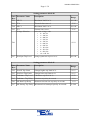
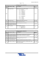
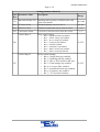
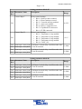
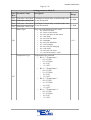
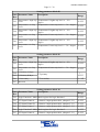
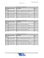
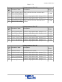
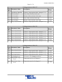
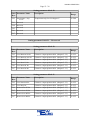
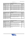
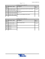
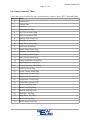
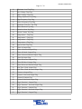
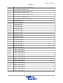
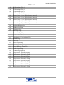
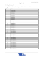
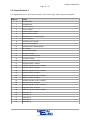
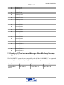
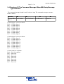
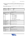
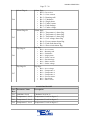
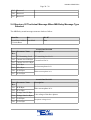
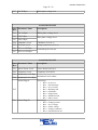
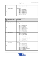
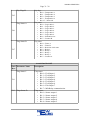
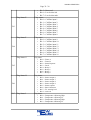
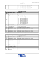
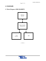
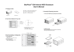
NC-MK1-PROFI-DP1
Page 1 / 38
MB-Relay CANbus BBRTU
User Manual
MB-CAN-BBRTU
Version 01.02
(NE_MB-CAN-BBRTU_MAN_01_10_FN02)
17 February 2011
NewElec Pretoria (Pty) Ltd
Head Office: c/o 298 Soutter street & Maltzan street
Pretoria West
South-Africa
0182
GPS: 25°45'12''S 28°09'46''E
Http://www.newelec.co.za
NC-MK1-PROFI-DP1
Page 2 / 38
Content
1. ABSTRACT............................................................................................................................3
2. SPECIFICATIONS.................................................................................................................4
2.1 Technical Specifications of MB-CAN-BBRTU................................................................4
2.2 Structure Of The Settings Telegram When MA-CAN messages Selected.......................5
2.3 Structure Of The Settings Telegram When MB-CAN messages Selected........................5
2.2.1 Input Pointers 1 Table.............................................................................................18
2.2.2 Input Pointers 2........................................................................................................22
2.2.3 Input Pointers 3........................................................................................................23
2.3 Structure Of The Command Message When MA-Relay Message Type Selected..........24
2.4 Structure Of The Command Message When MB-Relay Message Type Selected..........25
2.5 Structure Of The Actual Message When MA-Relay Message Type Selected................26
2.6 Structure Of The Actual Message When MB-Relay Message Type Selected................28
3. DEFINITIONS AND TERMINOLOGY..............................................................................35
4. FUNCTIONAL DESCRIPTION..........................................................................................36
5. OPERATING INSTRUCTIONS...........................................................................................37
5.1 Getting Started................................................................................................................37
5.1.1 Setting Up The MB-CAN-BBRTU..........................................................................37
5.2 Monitoring Diagnostic On Front-End.............................................................................37
6. DIAGRAMS.........................................................................................................................38
6.1 Block Diagram of MB-CAN-BBRTU............................................................................38
NC-MK1-PROFI-DP1
Page 3 / 38
1. ABSTRACT
The MB-CAN-BBRTU (MB-Relay CANbus BBRTU) acts as a translator between the
CANbus SCADA and the MB-Relay. It is advisable to read the MB-Relay user manual, as
some of the topics will require knowledge on the MB-Relay. It is also advisable to have
knowledge on CANbus.
The communication protocol between the MB-Relay and SCADA is CANbus.
Communication protocol between the MB-CAN-BBRTU and the MB-Relay is a NewElec
proprietary protocol. Enabling the PLC to communicate with the MB-Relay via CANBus.
NC-MK1-PROFI-DP1
Page 4 / 38
2. SPECIFICATIONS
2.1 Technical Specifications of MB-CAN-BBRTU
General Data
MB-CANBBRTU
Mounting Positions
Allowed Ambient Temperature
Humidity
Power Supply
Consumption
Communication Mediums
Protocol
Baud Rate
Cable Length @ Baud Rate
CANbus
Termination Resistor
(Termination resistors must be
connected at the beginning and
end of bus)
Type
LED Indications
Indication
Lights
●
●
●
●
●
●
●
●
●
●
●
●
●
●
●
●
●
Bottom of MB-Relay.
Operation : 0 ºC to +60 ºC
< 87%
+5Vdc
180 mA
CAnBUS
I2C
CANbus
125kbps.
250kbps.
500kbps.
1200 m @ 9600 bit/s to 45450 bit/s
1000 m @93.75Kbit/s to 187.5Kbit/s
400 m @ 500 Kbit/s
200 m @ 1.5 Mbit/s
100 m @ 3 Mbit/s to 12 Mbit/s
120 Ohm.
● Light Emitting Diode (LED)
● SCADA Communication
◦ Red = Tx data.
◦ Green = Rx data.
◦ Orange = Both.
● Address Of Module
◦ Flash Green = Address 1.
◦ Flash Red = Address 10.
◦ Flash Orange = Address 100.
◦ Solid Orange = Starting up.
◦ Colour Flash = MB-Re lay
comms OK.
NC-MK1-PROFI-DP1
Page 5 / 38
2.2 Structure Of The Settings Telegram When MA-CAN messages
Selected
The MB-Relay CAN module can setup the MB-Relay so that the MB-Relay and the MBCAN-BBRTU can act as a MA-Relay and MA-CAN-BBRTU. The setting structure will look
as follow:
Identifier
D0
D1
Setting Base
Address
Unit Address Block address.
D2~D7
Data that must be written to the relay.
2.3 Structure Of The Settings Telegram When MB-CAN messages
Selected
Due to the amount of settings that the MB-Relay has the messages had to be broken up into
the following messages. All the telegrams will fall under the same identifier of the Setting
data base address. MB-Relay setting telegram will look as follow:
Identifier
D0
D1
Setting Base
Address
Unit Address Block address.
D2~D7
Data that must be written to the relay.
NC-MK1-PROFI-DP1
Page 6 / 38
Setting parameter block 00
Data Parameter Name
Byte
Description
Range
D2
MLC0
Maximum load 0 in %.
10~100
D3
TC0
Thermal class curve 0.
5~25
D4
MLC1
Maximum load 1 in %.
10~100
D5
TC1
Thermal class curve 1.
5~25
Voltage Selection
Select line voltage value
• 0 = 110 Vac
• 1 = 380 Vac
• 2 = 400 Vac
• 3 = 525 Vac
• 4 = 550 Vac
• 5 = 680 Vac
• 6 = 950 Vac
• 7 = 1K1 Vac
• 8 = 3K3 Vac
• 9 = 6K6 Vac
• 10 = 11K Vac
0~10
D6
D7
Volt Sym Trip Level
Voltage symmetric trip level in %.
60~100
Setting parameter block 01
Data Parameter Name
Byte
Description
Range
D2
Volt Hi Trip Limit
Voltage higher trip limit in %.
0~15
D3
Volt Low Trip Limit
Voltage lower trip limit in %.
0~15
D4
Unbalance Trip Level
Unbalance trip level in %.
0~50
D5
Unbalance Trip Delay
Unbalance trip delay in seconds.
1~10
D6
ML Run Trip Delay
Minimum load run time trip delay in seconds.
1~10
D7
ML Startup Trip Delay Minimum load startup trip delay in seconds.
0~200
NC-MK1-PROFI-DP1
Page 7 / 38
Setting parameter block 02
Data Parameter Name
Byte
ML Reset Time
D2
Description
Minimum load reset time value.
• 01 = Manual.
• 02 = 10 Seconds.
• 03 = 5 Minutes.
• 04 = 10 Minutes.
• 05 = 20 Minutes.
• 06 = 30 Minutes.
• 07 = 45 Minutes.
• 08 = 1 Hour.
• 09 = 3 Hours.
• 10 = 6 Hours.
Range
0~10
D3
ML Trip Level
Minimum load trip level in %.
10~100
D4
ML Power Trip Level
Power trip level in %.
10~100
D5
EL Lo Byte Trip Level Earth leakage trip level in mA.
D6
EL Hi Byte Trip Level
EL Trip Type
D7
Earth leakage trip type.
• 0 = Instantaneous.
• 1 = IDMT curve.
0~999
0~1
Setting parameter block 03
Data Parameter Name
Byte
D2
Description
D3
EL Lo Byte Trip Time Earth leakage instantaneous trip time in
EL Hi Byte Trip Time milliseconds with 50ms incremental.
D4
Run Stall Lo Byte Level
D5
Run Stall Hi Byte Level
D6
Run Stall Hold Time
Running stall hold off trip delay in seconds.
Run Stall Lo Byte TD
Running stall trip delay in milliseconds with
50ms incremental..
D7
Running stall trip level in %.
Range
100~1000
110~300
0~200
100~2000
NC-MK1-PROFI-DP1
Page 8 / 38
Setting parameter block 04
Data Parameter Name
Byte
Description
Range
Run Stall Hi Byte TD
Running stall trip delay in milliseconds with
50ms incremental..
D3
TC Reset Level
Thermal capacity reset level in %.
20~80
D4
Starts Per Hour
Amount of starts that can be done in a hour.
1~60
D5
Consecutive Starts
Consecutive starts that can be done after a start.
1~3
Control Byte A
Relay control settings.
• Bit 0 = Minimum load trip enabled.
• Bit 1 = Under voltage trip enabled.
• Bit 2 = Over voltage trip enabled.
• Bit 3 = Volt Sym trip enabled.
• Bit 4 = Failsafe enabled.
• Bit 5 = Unbalance trip enabled.
• Bit 6 = Phase rotation trip enabled.
• Bit 7 = Short circuit trip enabled.
0~255
Relay control settings.
• Bit 0 = Single phase trip enabled.
• Bit 1 = Running stall trip enabled.
• Bit 2 = ML or PF selected for ML trip.
• Bit 3 = Earth leakage trip enabled.
• Bit 4 = Low pass filter enabled.
• Bit 5 = Insulation lockout trip enabled.
• Bit 6 = Frequency trip enabled.
• Bit 7 = TC reset auto calculate.
0~255
D2
D6
Control Byte B
D7
100~2000
NC-MK1-PROFI-DP1
Page 9 / 38
Setting parameter block 05
Data Parameter Name
Byte
Control Byte C
D2
Control Byte D
D3
Description
Range
Relay control settings.
• Bit 0 = Starts per hour enabled.
• Bit 1 = Phase rotation reversed.
• Bit 2 = Vectorial stall trip enabled.
• Bit 3 = Auto reset enabled.
• Bit 4 = Relay 1 assigned as I/O.
• Bit 5 = Expanded I/O connected.
• Bit 6 = FLED connected.
0~255
Relay Control settings.
• Bit 0 = Temperature 1 trip enabled.
• Bit 1 = Temperature 2 trip enabled.
• Bit 2 = Temperature 3 trip enabled.
• Bit 3 = Temperature 4 trip enabled
• Bit 4 = ClassF_Sel
0~15
D4
Field Input 1 Delay LoB Field input 1 switch delay in milliseconds with
D5
Field Input 1 Delay HiB
D6
Field Input 2 Delay LoB Field input 2 switch delay in milliseconds with
D7
Field Input 2 Delay HiB
50 ms incremental.
50 ms incremental.
0~2000
0~2000
Setting parameter block 06
Data Parameter Name
Byte
Description
D2
Field Input 3 Delay LoB Field input 3 switch delay in milliseconds with
D3
Field Input 3 Delay HiB
D4
Field Input 4 Delay LoB Field input 4 switch delay in milliseconds with
D5
Field Input 4 Delay HiB
D6
Field Input 5 Delay LoB Field input 1 switch delay in milliseconds with
D7
Field Input 5 Delay HiB
50 ms incremental.
50 ms incremental.
50 ms incremental.
Range
0~2000
0~2000
0~2000
NC-MK1-PROFI-DP1
Page 10 / 38
Setting parameter block 07
Data Parameter Name
Byte
D2
Description
Field Input 6 Delay HiB
D3
Field input 6 switch delay in milliseconds with
Field Input 6 Delay LoB 50 ms incremental.
D4
Field Input 7 Delay HiB
D5
Field input 7 switch delay in milliseconds with
Field Input 7 Delay LoB 50 ms incremental.
Starter Type
D6
Temperature Type
D7
Select one of the following starter values.
• 00 = Protection relay.
• 01 = Direct on line starter.
• 02 = Reversal direct on line starter.
• 03 = Star-Delta.
• 04 = Reversal Star-Delta.
• 05 = Dahlander
• 06 = Reversal Dahlander.
• 07 = Pole changing.
• 08 = Reversal pole changing.
• 09 = Soft starter.
• 10 = Reversal soft starter.
• 11 = Oil circuit breaker – DOL.
Temperature type selection
• Bit 0 ~ 1 Temperature 1
◦ 00 = PT100
◦ 01 = PT1000
◦ 10 = PTC
◦ 11 = NTC
• Bit 2 ~ 3 Temperature 2
◦ 00 = PT100
◦ 01 = PT1000
◦ 10 = PTC
◦ 11 = NTC
• Bit 4 ~ 5 Temperature 3
◦ 00 = PT100
◦ 01 = PT1000
◦ 10 = PTC
◦ 11 = NTC
• Bit 6 ~ 7 Temperature 4
◦ 00 = PT100
◦ 01 = PT1000
◦ 10 = PTC
◦ 11 = NTC
Range
0~2000
0~2000
0~11
NC-MK1-PROFI-DP1
Page 11 / 38
Setting parameter block 08
Data Parameter Name
Byte
Description
Range
D2
Temperature 1 High Trip Temperature 1 higher trip level. x – 30 =
Level
degree
0~255
D3
Temperature 1 Lo Trip
Level
0~255
D4
Temperature 2 High Trip Temperature 2 higher trip level. x – 30 =
Level
degree
0~255
D5
Temperature 2 Lo Trip
Level
0~255
D6
Temperature 3 High Trip Temperature 3 higher trip level. x – 30 =
Level
degree
0~255
D7
Temperature 3 Lo Trip
Level
0~255
Temperature 1 lower trip level. x – 30 = degree
Temperature 2 lower trip level. x – 30 = degree
Temperature 3 lower trip level. x – 30 = degree
Setting parameter block 09
Data Parameter Name
Byte
Description
Range
D2
Temperature 4 High Trip Temperature 4 higher trip level. x – 30 =
Level
degree
0~255
D3
Temperature 4 Lo Trip
Level
Temperature 4 lower trip level. x – 30 = degree
0~255
D4
CT Primary Lo Byte
D5
CT Primary Hi Byte
CT primary
1~
65535
D6
CT Secondary
CT secondary
1 ~ 255
D7
Reserved
Setting parameter block 10
Data Parameter Name
Byte
Description
Range
D2
Logic Function 1 Mask Mask register for logic function 1.
0~255
D3
LF1 Input Pointer A
Points to a input pointer table. (chapter 2.2.1)
0~255
D4
LF1 Input Pointer B
Points to a input pointer table. (chapter 2.2.1)
0~255
D5
LF1 Input Pointer C
Points to a input pointer table. (chapter 2.2.1)
0~255
D6
Logic Function 2 Mask Mask register for logic function 2.
0~255
D7
LF2 Input Pointer A
0~255
Points to a input pointer table. (chapter 2.2.1)
NC-MK1-PROFI-DP1
Page 12 / 38
Setting parameter block 11
Data Parameter Name
Byte
Description
Range
D2
LF2 Input Pointer A
Points to a input pointer table. (chapter 2.2.1)
0~255
D3
LF2 Input Pointer B
Points to a input pointer table. (chapter 2.2.1)
0~255
D4
Logic Function 3 Mask Mask register for logic function 3.
0~255
D5
LF3 Input Pointer A
Points to a input pointer table. (chapter 2.2.1)
0~255
D6
LF3 Input Pointer B
Points to a input pointer table. (chapter 2.2.1)
0~255
D7
LF3 Input Pointer C
Points to a input pointer table. (chapter 2.2.1)
0~255
Setting parameter block 12
Data Parameter Name
Byte
Description
Range
D2
Logic Function 4 Mask Mask register for logic function 4.
0~255
D3
LF4 Input Pointer A
Points to a input pointer table. (chapter 2.2.1)
0~255
D4
LF4 Input Pointer B
Points to a input pointer table. (chapter 2.2.1)
0~255
D5
LF4 Input Pointer C
Points to a input pointer table. (chapter 2.2.1)
0~255
D6
Logic Function 5 Mask Mask register for logic function 5.
0~255
D7
LF5 Input Pointer A
0~255
Points to a input pointer table. (chapter 2.2.1)
Setting parameter block 13
Data Parameter Name
Byte
Description
Range
D2
LF5 Input Pointer B
Points to a input pointer table. (chapter 2.2.1)
0~255
D3
LF5 Input Pointer C
Points to a input pointer table. (chapter 2.2.1)
0~255
D4
Logic Function 6 Mask Mask register for logic function 6.
0~255
D5
LF6 Input Pointer A
Points to a input pointer table. (chapter 2.2.1)
0~255
D6
LF6 Input Pointer B
Points to a input pointer table. (chapter 2.2.1)
0~255
D7
LF6 Input Pointer C
Points to a input pointer table. (chapter 2.2.1)
0~255
NC-MK1-PROFI-DP1
Page 13 / 38
Setting parameter block 14
Data Parameter Name
Byte
D2
Description
Range
D3
Timer A Time Lo Byte Time it will take for timer A to time out in
Timer A Time Hi Byte seconds.
0~3000
D4
Timer A Start Pointer
Points to a input pointer table. (chapter 2.2.1)
0~255
D5
Timer A Reset Pointer Points to a input pointer table. (chapter 2.2.1)
0~255
D6
Timer B Time Lo Byte Time it will take for timer B to time out in
Timer B Time Hi Byte seconds.
0~3000
D7
Setting parameter block 15
Data Parameter Name
Byte
Description
Range
D2
Timer B Start Pointer
Points to a input pointer table. (chapter x.x.x)
0~255
D3
Timer B Reset Pointer Points to a input pointer table. (chapter x.x.x)
0~255
D4
Counter A Limit
Count limit to be reached.
0~255
D5
Counter A Count Up Ptr
Points to a input pointer table. (chapter 2.2.1)
0~255
D6
Cntr A Count Down Ptr
Points to a input pointer table. (chapter 2.2.1)
0~255
D7
Cntr A Count Reset Ptr
Points to a input pointer table. (chapter 2.2.1)
0~255
Setting parameter block 16
Data Parameter Name
Byte
Description
Range
D2
Counter B Limit
Count limit to be reached.
0~255
D3
Counter B Count Up Ptr
Points to a input pointer table. (chapter 2.2.1)
0~255
D4
Cntr B Count Down Ptr
Points to a input pointer table. (chapter 2.2.1)
0~255
D5
Cntr B Count Reset Ptr
Points to a input pointer table. (chapter 2.2.1)
0~255
D6
Status Rep Input Pointer Points to a input pointer table. (chapter 2.2.3)
0~255
D7
Latch Set Input Pointer
0~255
Points to a input pointer table. (chapter 2.2.1)
NC-MK1-PROFI-DP1
Page 14 / 38
Setting parameter block 17
Data Parameter Name
Byte
Description
Range
D2
Latch Reset Input Ptr
Points to a input pointer table. (chapter 2.2.1)
0~255
D3
RTC Start Hour
Hour of the real time clock start.
0~23
D4
RTC Start Min
Minutes of the real time clock start.
0~59
D5
RTC Stop Hour
Hour of the real time clock stop.
0~255
D6
RTC Start Min
Minutes of the real time clock stop.
0~255
D7
Relay 1 Input Pointer
Points to a input pointer table. (chapter 2.2.1)
0~255
Setting parameter block 18
Data Parameter Name
Byte
Description
Range
D2
Relay 2 Input Pointer
Points to a input pointer table. (chapter 2.2.1)
0~255
D3
Relay 3 Input Pointer
Points to a input pointer table. (chapter 2.2.1)
0~255
D4
Relay 4 Input Pointer
Points to a input pointer table. (chapter 2.2.1)
0~255
D5
Relay 5 Input Pointer
Points to a input pointer table. (chapter 2.2.1)
0~255
D6
Relay 6 Input Pointer
Points to a input pointer table. (chapter 2.2.1)
0~255
D7
Relay 7 Input Pointer
Points to a input pointer table. (chapter 2.2.1)
0~255
Setting parameter block 19
Data Parameter Name
Byte
Description
Range
D2
Relay 8 Input Pointer
Points to a input pointer table. (chapter 2.2.1)
0~255
D3
Relay 9 Input Pointer
Points to a input pointer table. (chapter 2.2.1)
0~255
D4
Reset Input Pointer
Points to a input pointer table. (chapter 2.2.3)
0~255
D5
TC Warning Level.
TC Level > TC warning level in %.
0~100
D6
Temperature 1 Trip
Level
Temperature trip level in degree C.
0~200
D7
Temperature 2 Trip
Level
Temperature trip level in degree C.
0~200
NC-MK1-PROFI-DP1
Page 15 / 38
Setting parameter block 20
Data Parameter Name
Byte
D2
Temperature 3 Trip
Level
D3
Reserved
D4
Reserved
D5
Reserved
D6
Reserved
D7
Reserved
Description
Temperature trip level in degree C.
Range
0~200
Setting parameter block 21 ~ 29 reserved
Setting parameter block 30
Data Parameter Name
Byte
Description
Range
D2
Local Remote lsb Ptr
Points to a input pointer table. (chapter 2.2.2)
0~255
D3
Local Remote msb Ptr
Points to a input pointer table. (chapter 2.2.2)
0~255
D4
Local Start FF Ptr
Points to a input pointer table. (chapter 2.2.3)
0~255
D5
Local Start FS Ptr
Points to a input pointer table. (chapter 2.2.3)
0~255
D6
Local Start RF Ptr
Points to a input pointer table. (chapter 2.2.3)
0~255
D7
Local Start RS Ptr
Points to a input pointer table. (chapter 2.2.3)
0~255
Setting parameter block 31
Data Parameter Name
Byte
Description
Range
D2
Local Interlock Ptr
Points to a input pointer table. (chapter 2.2.3)
0~255
D3
Local Stop Ptr
Points to a input pointer table. (chapter 2.2.3)
0~255
D4
Remote Start FF Ptr
Points to a input pointer table. (chapter 2.2.3)
0~255
D5
Remote Start FS Ptr
Points to a input pointer table. (chapter 2.2.3)
0~255
D6
Remote Start RF Ptr
Points to a input pointer table. (chapter 2.2.3)
0~255
D7
Remote Start RS Ptr
Points to a input pointer table. (chapter 2.2.3)
0~255
NC-MK1-PROFI-DP1
Page 16 / 38
Setting parameter block 32
Data Parameter Name
Byte
Description
Range
D2
Remote Interlock Ptr
Points to a input pointer table. (chapter 2.2.3)
0~255
D3
Remote Stop Ptr
Points to a input pointer table. (chapter 2.2.3)
0~255
D4
Auto Start FF Ptr
Points to a input pointer table. (chapter 2.2.3)
0~255
D5
Auto Start FS Ptr
Points to a input pointer table. (chapter 2.2.3)
0~255
D6
Auto Start RF Ptr
Points to a input pointer table. (chapter 2.2.3)
0~255
D7
Auto Start RS Ptr
Points to a input pointer table. (chapter 2.2.3)
0~255
Setting parameter block 33
Data Parameter Name
Byte
Description
Range
D2
Auto Interlock Ptr
Points to a input pointer table. (chapter 2.2.3)
0~255
D3
Auto Stop Ptr
Points to a input pointer table. (chapter 2.2.3)
0~255
D4
Feedback signal input Ptr Points to a input pointer table. (chapter 2.2.3)
0~255
D5
Prewarning Tmr Lo Byte Pre start warning alarm in seconds.
D6
Prewarning Tmr Hi Byte
D7
Execution Timer
Time it should take to execute a start in sec.
0~10
Setting parameter block 34
Data Parameter Name
Byte
Description
D2
Feedback Timer Lo Byte Time for the feedback signal to be active in
D3
Feedback Timer Hi Byte milliseconds with 50ms incremental.
D4
Backspin Timer Lo Byte Timer for the motor to back spin before
D5
Backspin Timer Hi Byte
D6
DC Break Time Lo Byte Time to break the motor when a stop is
D7
DC Break Time Hi Byte
starting the motor again in milliseconds.
executed.
Range
0~2000
NC-MK1-PROFI-DP1
Page 17 / 38
Setting parameter block 35
Data Parameter Name
Byte
Description
D2
Restart Timer Lo Byte
D3
Restart Timer Hi Byte
D4
Star Max Timer Lo Byte Maximum time delay between star and delta
D5
Star Max Timer Hi Byte
D6
Transition Time Lo Byte Time to go from high to low speed..
D7
Transition Time Hi Byte
Time to restart the motor after a power down
happened.
Range
0~2000
change over..
Setting parameter block 36
Data Parameter Name
Byte
D2
FC Timer Lo Byte
D3
FC Timer Hi Byte
D4
Reserved
D5
Reserved
D6
Reserved
D7
Reserved
Description
Frozen contact timer.
Range
0~2000
NC-MK1-PROFI-DP1
Page 18 / 38
2.2.1 Input Pointers 1 Table
Values that can be routed to the logic function tables, counters, timers, RTC, latch and flasher.
Address Name
0
Constant Zero.
1
Constant One.
2
In Service.
3
Voltage Present Flag.
4
Over Current Alarm Flag.
5
Short Circuit Alarm Flag.
6
Running Stall Alarm Flag.
7
Unbalance Alarm Flag.
8
Single Phase Alarm Flag.
9
Earth Fault Alarm Flag.
10
Earth Leakage Alarm Flag.
11
Minimum Load Alarm Flag.
12
Over Voltage Alarm Flag.
13
Under Voltage Alarm Flag.
14
Voltage Symmetric Alarm Flag.
15
High Frequency Alarm Flag.
16
Lower Frequency Alarm Flag.
17
Insulation Alarm Flag.
18
Frozen Contact Alarm Flag.
19
Temperature 1 Alarm Flag
20
Temperature 2 Alarm Flag
21
Temperature 3 Alarm Flag
22
Temperature 4 Alarm Flag
23
Over Current Trip Flag.
24
Short Circuit Trip Flag.
25
Running Stall Trip Flag.
26
Unbalance Trip Flag.
27
Single Phase Trip Flag.
28
Earth Fault Trip Flag.
29
Earth Leakage Trip Flag.
NC-MK1-PROFI-DP1
Page 19 / 38
30
Minimum Load Trip Flag.
31
Over Voltage Trip Flag.
32
Under Voltage Trip Flag.
33
Voltage Symmetric Trip Flag.
34
High Frequency Trip Flag.
35
Lower Frequency Trip Flag.
36
Insulation Lock Out Trip Flag.
37
Phase Rotation Trip Flag.
38
Starts Per Hour Trip Flag.
39
Frozen Contact Trip Flag.
40
Temperature 1 Trip Flag
41
Temperature 2 Trip Flag
42
Temperature 3 Trip Flag
43
Temperature 4 Trip Flag
44
System Fault Trip Flag
45
Timer A Output Flag.
46
Timer A Inverted Output Flag.
47
Timer A Pulsed Output Flag.
48
Timer A Inverted Pulsed Output Flag.
49
Timer B Output Flag.
50
Timer B Inverted Output Flag.
51
Timer B Pulsed Output Flag.
52
Timer B Inverted Pulsed Output Flag.
53
Real Time Clock Output Flag.
54
Real Time Clock Inverted Output Flag.
55
Counter A Output Flag.
56
Counter A Inverted Output Flag.
57
Counter B Output Flag.
58
Counter B Inverted Output Flag.
59
Logic Function 1 Output Flag.
60
Logic Function 1 Inverted Output Flag.
61
Logic Function 2 Output Flag.
62
Logic Function 2 Inverted Output Flag.
63
Logic Function 3 Output Flag.
NC-MK1-PROFI-DP1
Page 20 / 38
64
Logic Function 3 Inverted Output Flag.
65
Logic Function 4 Output Flag.
66
Logic Function 4 Inverted Output Flag.
67
Logic Function 5 Output Flag.
68
Logic Function 5 Inverted Output Flag.
69
Logic Function 6 Output Flag.
70
Logic Function 6 Inverted Output Flag.
71
Digital Input Flag 1.
72
Digital Input Flag 2.
73
Digital Input Flag 3.
74
Digital Input Flag 4.
75
Digital Input Flag 5.
76
Digital Input Flag 6.
77
Digital Input Flag 7.
78
Digital Input Flag 8.
79
Digital Input Flag 9.
80
Digital Input Flag 10.
81
Digital Input Flag 11.
82
Digital Input Flag 12.
83
Digital Input Flag 13.
84
Digital Input Flag 14.
85
Digital Input Flag 15.
86
CANbus Input Flag 01.
87
CANbus Input Flag 02.
88
CANbus Input Flag 03.
89
CANbus Input Flag 04.
90
CANbus Input Flag 05.
91
CANbus Input Flag 06.
92
CANbus Input Flag 07.
93
CANbus Input Flag 08.
94
CANbus Input Flag 09.
95
CANbus Input Flag 10.
96
CANbus Input Flag 11.
97
CANbus Input Flag 12.
NC-MK1-PROFI-DP1
Page 21 / 38
98
CANbus Input Flag 13.
99
CANbus Input Flag 14.
100
CANbus Input Flag 15.
101
CANbus Input Flag 16.
102
Starter Output 1 (See MB-Relay user manual)
103
Starter Output 2 (See MB-Relay user manual)
104
Starter Output 3 (See MB-Relay user manual)
105
Starter Output 4 (See MB-Relay user manual)
106
Starter Output 5 (See MB-Relay user manual)
107
Pre Start Warning Flag.
108
DC Breaking Flag.
109
Transition Flag.
110
Back Spin Flag.
111
Execution Trip Flag.
112
Feedback Trip Flag.
113
Unauthorized Current Alarm Flag.
114
Restart Flag.
115
Trip Flag.
116
Pulse Output Flag.
117
Flash Output Flag.
118
Status Reporter Output Flag.
119
Latch Output Flag.
120
TC Warning High Flag
121
Temperature 1 Warning Hi Flag
122
Temperature 1 Warning Lo Flag
123
Temperature 2 Warning Hi Flag
124
Temperature 2 Warning Lo Flag
125
Temperature 3 Warning Hi Flag
126
Temperature 3 Warning Lo Flag
127
Temperature 4 Warning Hi Flag
128
Temperature 4 Warning Lo Flag
NC-MK1-PROFI-DP1
Page 22 / 38
2.2.2 Input Pointers 2
It is signals that can be routed to the inputs of the local and remote selection.
Address
Name
0
Constant Zero
1
Constant One
2
Field Input 1
3
Field Input 2
4
Field Input 3
5
Field Input 4
6
Field Input 5
7
Field Input 6
8
Field Input 7
9
Field Input 8
10
Field Input 9
11
Field Input 10
12
Field Input 11
13
Field Input 12
14
Field Input 13
15
Field Input 14
16
Field Input 15
17
PLC Input Bit 1
18
PLC Input Bit 2
19
PLC Input Bit 3
20
PLC Input Bit 4
21
PLC Input Bit 5
22
PLC Input Bit 6
23
PLC Input Bit 7
24
PLC Input Bit 8
25
PLC Input Bit 9
26
PLC Input Bit 10
27
PLC Input Bit 11
28
PLC Input Bit 12
29
PLC Input Bit 13
30
PLC Input Bit 14
31
PLC Input Bit 15
32
PLC Input Bit 16
NC-MK1-PROFI-DP1
Page 23 / 38
2.2.3 Input Pointers 3
It is signals that can be routed to the inputs of the starter logic starts, stops and interlock.
Address
Name
0
Constant Zero
1
Constant One
2
In Service Flag
3
Timer A Output
4
Inverted Timer A Output
5
Timer A Pulsed Output
6
Inverted Timer A Pulsed Output
7
Timer B Output
8
Inverted Timer B Output
9
Timer B Pulsed Output
10
Inverted Timer B Pulsed Output
11
RTC Output
12
Inverted RTC Output
13
Counter A Output
14
Inverted Counter A Output
15
Counter B Output
16
Inverted Counter B Output
17
Logical Function 1 Output
18
Inverted Logical Function 1 Output
19
Logical Function 2 Output
20
Inverted Logical Function 2 Output
21
Logical Function 3 Output
22
Inverted Logical Function 3 Output
23
Logical Function 4 Output
24
Inverted Logical Function 4 Output
25
Logical Function 5 Output
26
Inverted Logical Function 5 Output
27
Logical Function 6 Output
28
Inverted Logical Function 6 Output
29
Field Input 1
30
Field Input 2
31
Field Input 3
32
Field Input 4
33
Field Input 5
NC-MK1-PROFI-DP1
Page 24 / 38
34
Field Input 6
35
Field Input 7
36
Field Input 8
37
Field Input 9
38
Field Input 10
39
Field Input 11
40
Field Input 12
41
Field Input 13
42
Field Input 14
43
Field Input 15
44
PLC Input Bit 1
35
PLC Input Bit 2
36
PLC Input Bit 3
37
PLC Input Bit 4
48
PLC Input Bit 5
49
PLC Input Bit 6
50
PLC Input Bit 7
51
PLC Input Bit 8
52
PLC Input Bit 9
53
PLC Input Bit 10
54
PLC Input Bit 11
55
PLC Input Bit 12
56
PLC Input Bit 13
57
PLC Input Bit 14
58
PLC Input Bit 15
59
PLC Input Bit 16
2.3 Structure Of The Command Message When MA-Relay Message
Type Selected
MB-CAN-BBRTU kept back wards compatibility with the MA-CAN-BBRTU. The command
message length was only three bytes long. The command messages structure looks as follow:
Identifier
D0
D1
Command Base
Address
Unit Address
Control Byte A.
D2
Control Byte B.
NC-MK1-PROFI-DP1
Page 25 / 38
2.4 Structure Of The Command Message When MB-Relay Message
Type Selected
The command message length is only four bytes long. The command messages structure
looks as follow:
Identifier
D0
Command Base Unit Address
Address
SCADA Input 1 bits are as follow:
Bit 0 = CANbus Input 1.
Bit 1 = CANbus Input 2.
Bit 2 = CANbus Input 3.
Bit 3 = CANbus Input 4.
Bit 4 = CANbus Input 5.
Bit 5 = CANbus Input 6.
Bit 6 = CANbus Input 7.
Bit 7 = CANbus Input 8.
SCADA Input 2 bits are as follow:
Bit 0 = CANbus Input 9.
Bit 1 = CANbus Input 10.
Bit 2 = CANbus Input 11.
Bit 3 = CANbus Input 12.
Bit 4 = CANbus Input 13.
Bit 5 = CANbus Input 14.
Bit 6 = CANbus Input 15.
Bit 7 = CANbus Input 16.
Control A bits are as follow:
Bit 0 = Fail Safe enabled.
Bit 1 = Reserved.
Bit 2 = Reserved.
Bit 3 = Reserved.
Bit 4 = Reserved.
Bit 5 = Reserved.
Bit 6 = Reserved.
Bit 7 = Reserved.
D1
D2
SCADA Input 0 SCADA Input 1
D4
Control A.
NC-MK1-PROFI-DP1
Page 26 / 38
2.5 Structure Of The Actual Message When MA-Relay Message Type
Selected
MB-CAN-BBRTU kept back wards compatibility with the MA-CAN-BBRTU. The actual
messages structure looks as follow:
Identifier
D0
D1~D7
Actual Base Address Data block
+ Unit Address
Data
Actual data block 00
Data Parameter Name
Byte
Description
Input flags
Field input flags.
• Bit 0 = Field Input 1.
• Bit 1 = Field Input 2.
• Bit 2 = Field Input 3.
• Bit 3 = Field Input 4.
• Bit 4 = Field Input 5.
• Bit 5 = Reserved.
• Bit 6 = Reserved.
• Bit 7 = MB-Communication Status.
D2
TC Remaining
TC remaining level in %.
D3
Ir Hi Byte
D4
Ir Lo Byte
D5
Iw Hi Byte
D6
Iw Lo Byte
D7
Ib Hi Byte
D1
Red current phase level in %.
White current phase level in %.
Blue current phase level in %.
Actual data block 01
Data Parameter Name
Byte
Description
D1
Ib Lo Byte
Blue current phase level in %.
D2
Voltage line level
Multiply line voltage by 5.469 to get the voltage value.
D3
EL Level
Earth leakage level in mA. Multiply by 10 to get value.
NC-MK1-PROFI-DP1
Page 27 / 38
Alarm Flags A
Alarm flags.
• Bit 0 = In service.
• Bit 1 = Over current.
• Bit 2 = Running stall.
• Bit 3 = Unbalance.
• Bit 4 = Single phase.
• Bit 5 = Under current.
• Bit 6 = Earth leakage.
• Bit 7 = Under voltage.
Alarm Flags B
Alarm flags.
• Bit 0 = Temperature 1 alarm flag.
• Bit 1 = Temperature 2 alarm flag.
• Bit 2 = Temperature 3 alarm flag.
• Bit 3 = Over voltage alarm flag.
• Bit 4 = Frozen contact alarm flag.
• Bit 5 = Earth fault alarm flag.
• Bit 6 = Short circuit alarm flag.
Trip flags A
Trip flags.
• Bit 0 = Over current.
• Bit 1 = Running stall.
• Bit 2 = Unbalance.
• Bit 3 = Single phase.
• Bit 4 = Under current.
• Bit 5 = Earth leakage.
• Bit 6 = Phase rotation.
• Bit 7 = Under voltage.
Trip flags B
Trip flags.
• Bit 0 = Over voltage.
• Bit 1 = Temperature 1.
• Bit 2 = Temperature 2.
• Bit 3 = Temperature 3.
• Bit 4 = Frozen contact.
• Bit 5 = Earth fault.
• Bit 6 = Short circuit.
D4
D5
D6
D7
Actual data block 02
Data Parameter Name
Byte
Description
D1
Unbalance Level
Unbalance level in %.
D2
Temperature 1 Level
Temperature 1 level in degree C.
D3
Temperature 2 Level
Temperature 2 level in degree C.
D4
Temperature 3 Level
Temperature 3 level in degree C.
NC-MK1-PROFI-DP1
Page 28 / 38
D5
Reserved
D6
Reserved
D7
Reserved
2.6 Structure Of The Actual Message When MB-Relay Message Type
Selected
The MB-Relay actual messages structure looks as follow:
Identifier
D0
D1~D7
Actual Base Address Data block
+ Unit Address
Data
Actual data block 00
Data Parameter Name
Byte
D1
TC Remaining Level
D2
Current Level Hi Byte
D3
Current Level Lo Byte
D4
Ir Hi Byte
D5
Ir Lo Byte
D6
Iw Hi Byte
D7
Iw Lo Byte
Description
TC remaining level in %.
Current level in %.
Red current phase in %
White current phase in %.
Actual data block 01
Data Parameter Name
Byte
D1
Ib Hi Byte
D2
Ib Lo Byte
D3
Voltage Line Hi Byte
D4
Voltage Line Lo Byte
D5
Vr Hi Byte
D6
Vr Lo Byte
Description
Blue current phase in %.
Line voltage of the three phases.
Red phase voltage level.
NC-MK1-PROFI-DP1
Page 29 / 38
D7
Vw Hi Byte
White phase voltage level.
Actual data block 02
Data Parameter Name
Byte
Description
D1
Vw Lo Byte
White phase voltage level.
D2
Vb Hi Byte
D3
Vb Lo Byte
D4
Unbalance Level
Unbalance level in %.
D5
Volt Sym Level
Voltage symmetric level in %.
D6
EL Level Hi Byte
D7
EL Level Lo Byte
Blue phase voltage level.
Earth leakage level in mA.
Actual data block 03
Data Parameter Name
Byte
Description
D1
Power Factor Level
Power factor level in %.
D2
Frequency Level
Frequency level in Hz.
D3
Insulation Lvl Hi Byte
D4
Insulation Lvl Lo Byte
Alarm Flags A
Alarm flags.
• Bit 0 = In service.
• Bit 1 = Earth leakage.
• Bit 2 = Over current.
• Bit 3 = Running stall.
• Bit 4 = Unbalance.
• Bit 5 = Single phase.
• Bit 6 = Minimum load.
• Bit 7 = Short circuit.
Alarm Flags B
Alarm flags.
• Bit 0 = Voltage present.
• Bit 1 = Over voltage.
• Bit 2 = Under voltage.
• Bit 3 = Voltage symmetric.
• Bit 4 = Insulation lock out.
D5
D6
Insulation level in ohms.
NC-MK1-PROFI-DP1
Page 30 / 38
•
•
•
Alarm Flags C
D7
Bit 5 = Low frequency.
Bit 6 = High frequency.
Bit 7 = Earth fault.
Alarm flags.
• Bit 0 = Vectorial stall.
• Bit 1 = Frozen contact.
• Bit 2 = Temperature 1.
• Bit 3 = Temperature 2.
• Bit 4 = Temperature 3.
• Bit 5 = Temperature 4.
• Bit 6~7 = Reserved.
Actual data block 04
Data Parameter Name
Byte
D1
Reserved
Trip Flags A
Trip flags.
• Bit 0 = Over current.
• Bit 1 = Running stall.
• Bit 2 = Unbalance.
• Bit 3 = Single phase.
• Bit 4 = Minimum load.
• Bit 5 = Short circuit.
• Bit 6 = Phase rotation.
• Bit 7 = Earth leakage.
Trip Flags B
Trip flags.
• Bit 0 = Over voltage.
• Bit 1 = Under voltage.
• Bit 2 = Voltage symmetric.
• Bit 3 = Insulation lockout.
• Bit 4 = Low frequency level.
• Bit 5 = High frequency level.
• Bit 6 = Earth Fault.
• Bit 7 = Starts per hour.
Trip Flags C
Trip flags.
• Bit 0 = System failure.
• Bit 1 = Vectorial stall.
• Bit 2 = Frozen contact.
• Bit 3 = Execution fault.
• Bit 4 = Feedback fault.
• Bit 5 = Unauthorized current.
• Bit 6~7 = Reserved.
D2
D3
D4
Description
NC-MK1-PROFI-DP1
Page 31 / 38
Trip Flags D
Trip flags.
• Bit 0 = Temperature 1.
• Bit 1 = Temperature 2.
• Bit 2 = Temperature 3.
• Bit 3 – Temperature 4.
• Bit 4~7 = Reserved.
Flag Status A
Flag status.
• Bit 0 = Logic table 1.
• Bit 1 = Logic table 2.
• Bit 2 = Logic table 3.
• Bit 3 = Logic table 4.
• Bit 4 = Logic table 5.
• Bit 5 = Logic table 6.
• Bit 6 = Simulation test.
• Bit 7 = Counter B.
Flag Status B
Flag status.
• Bit 0 = Timer A.
• Bit 1 = Timer B.
• Bit 2 = Real time clock start.
• Bit 3 = Relay 1.
• Bit 4 = Relay 2.
• Bit 5 = Relay 3.
• Bit 6 = Relay 4.
• Bit 7 = Counter A.
D5
D6
D7
Actual data block 05
Data Parameter Name
Byte
Flag Status C
Flag status.
• Bit 0 = Field input 1.
• Bit 1 = Field input 2.
• Bit 2 = Field input 3.
• Bit 3 = Field input 4.
• Bit 4 = Field input 5.
• Bit 5 = Field input 6.
• Bit 6 = Filed input 7.
• Bit 7 = MB-Relay communication.
Flags Status D
Flags status.
• Bit 0 = Starter output 1.
• Bit 1 = Starter output 2.
• Bit 2 = Starter output 3.
• Bit 3 = Starter output 4.
• Bit 4 = Starter output 5.
D1
D2
Description
NC-MK1-PROFI-DP1
Page 32 / 38
•
•
•
Flag Status E
Flags status.
• Bit 0 = CANbus input 1.
• Bit 1 = CANbus input 2.
• Bit 2 = CANbus input 3.
• Bit 3 = CANbus input 4.
• Bit 4 = CANbus input 5.
• Bit 5 = CANbus input 6.
• Bit 6 = CANbus input 7.
• Bit 7 = CANbus input 8.
Flag Status F
Flag status.
• Bit 0 = CANbus input 9.
• Bit 1 = CANbus input 10.
• Bit 2 = CANbus input 11.
• Bit 3 = CANbus input 12.
• Bit 4 = CANbus input 13.
• Bit 5 = CANbus input 14.
• Bit 6 = CANbus input 15.
• Bit 7 = CANbus input 16.
Flag Status G
Flag status.
• Bit 0 = Timer A.
• Bit 1 = Timer B.
• Bit 2 = Status Reporter.
• Bit 3 = Latch.
• Bit 4 = Relay 5.
• Bit 5 = Relay 6.
• Bit 6 = Relay 7.
• Bit 7 = Relay 8.
Flag Status H
Flag Status.
• Bit 0 = Starter output 6.
• Bit 1 = Starter output 7.
• Bit 2 = Starter output 8.
• Bit 3 = Starter output 9.
• Bit 5 = Status reporter.
• Bit 6 = Pulse Generator
• Bit 7 = TC warning level.
• Bit 4 = reserved.
Flag Status I
Flag Status.
• Bit 0 = Temperature 1 Warning High.
• Bit 1 = Temperature 1 Warning Lo.
• Bit 2 = Temperature 2 Warning High.
• Bit 3 = Temperature 2 Warning Lo.
D3
D4
D5
D6
D7
Bit 5 = Reserved.
Bit 6 = Local select lsb.
Bit 7 = Local select msb.
NC-MK1-PROFI-DP1
Page 33 / 38
•
•
•
•
Bit 4 = Temperature 3 Warning High.
Bit 5 = Temperature 3 Warning Lo.
Bit 6 = Temperature 14Warning High.
Bit 7 = Temperature 14Warning Lo.
Actual data block 06
Data Parameter Name
Byte
Description
Flag Status J
Flag status.
• Bit 0 = Field input 8.
• Bit 1 = Field input 9.
• Bit 2 = Field input 10.
• Bit 3 = Field input 11.
• Bit 4 = Field input 12.
• Bit 5 = Field input 13.
• Bit 6 = Filed input 14.
• Bit 7 = Filed input 15.
D2
Counter A Value
Current counter A value.
D3
Counter B Value
Current counter B value.
D4
Current MLC
Current MLC setting selected in %.
D5
Temperature 1 Level
Temperature 1 level in degree C. x- 30 = degrees
D6
Temperature 2 Level
Temperature 2 level in degree C. x- 30 = degrees
D7
Temperature 3 Level
Temperature 3 level in degree C. x- 30 = degrees
D1
Actual data block 07
Data Parameter Name
Byte
D1
Description
Temperature 4 Level
Temperature 4 level in degree C. x- 30 = degrees
Relay Model
0 = 005
1 = 010
2 = 050
3 = 100
4 = 300
D2
D3
CT Primary Hi Byte
D4
CT Primary Lo Byte
D5
CT Sencondary
D6
Reserved
NC-MK1-PROFI-DP1
Page 34 / 38
D7
Reserved
NC-MK1-PROFI-DP1
Page 35 / 38
3. DEFINITIONS AND TERMINOLOGY
CBCT
Core balance current transformer. Used to find the difference between
three phase current.
CT
Current transformer. Breaks down the current to lower current value.
EEPROM
Electrical Erasable Programmable Read Only Memory (non volatile)
Flash memory
Similar to EEPROM (only block write - non volatile)
In service
When the current rise above 10% of full load current it is assumed that
the motor is running.
Intrinsic safe
It is a protection technique for safe operation of electronic equipment in
explosive atmospheres. The concept was developed for safe operation of
process control instrumentation in hazardous areas. The theory behind
intrinsic safety is to ensure that the available electrical and thermal
energy in the system is always low enough that ignition of the hazardous
atmosphere cannot occur.
LED
Light emitting diode (It is used as visual indicators)
Motor protection
relay
It is an intelligent (computerized) unit monitoring an electric motor's
current and voltage supply. In case of overloading, phase lost etc. the
power supply of the motor will be interrupted by the protection relay to
prevent damage to the motor.
MB-CAN-BBRTU MB-Relay CANbus board bottom remote translating unit.
PLC
Programmable Logic Controller.
NC-MK1-PROFI-DP1
Page 36 / 38
4. FUNCTIONAL DESCRIPTION
The MB-CAN-BBRTU can be broken down into the following function blocks:
• Micro-Controller
• MB-Relay Interface.
• CANbus Interface.
• Light Emitting Diodes (LED)
Micro-Controller – Is the core of the system. The micro-controller ensures that the operation
of the MB-CAN-BBRTU gets executed. The micro-controller acts as a bridge between the
MB-Relay and the SCADA.
MB-Relay Interface – Is the communication bus between the MB-Relay and MB-CANBBRTU. With the MB-Relay interface it is possible for the two micro-controllers MB-Relay
and MB-CAN-BBRTU to exchange data.
CANbus Interface – Allows the MB-Relay to communicate with the SCAD. With the
CANbus interface it is possible to update the MB-CAN-BBRTU with new values as well as
the SCADA.
Light Emitting Diodes – Allows the MB-CAN-BBRTU to indicate conditions to the operator.
NC-MK1-PROFI-DP1
Page 37 / 38
5. OPERATING INSTRUCTIONS
5.1 Getting Started
5.1.1 Setting Up The MB-CAN-BBRTU
Following must be done via the MB-Relay front-end:
• Connect the MB-Relay front-end to the relay.
• Select the communication device as CANbus.
• Set the settings of the relay.
• Transmit the data to the relay.
5.2 Monitoring Diagnostic On Front-End
The front-end will shows the following diagnostics under the “Statistics” tab:
1. Canbus module present.
2. Software revision.
3. Communication status – Status of the CANbus.
4. Average cyclic message time – Time between cyclic messages.
5. Negative Error – Biggest negative time error between cyclic messages.
6. Positive Error – Biggest positive time error between cyclic messages.
NC-MK1-PROFI-DP1
Page 38 / 38
6. DIAGRAMS
6.1 Block Diagram of MB-CAN-BBRTU
MB-Relay
Interface
Micro-Controller
With Memory
CAN
Interface
LED
----ooOoo----