1
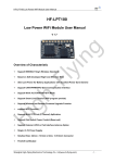
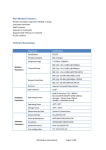
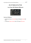
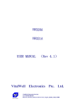
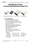
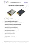
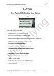
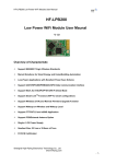
VW801 VW802 VW803 VW804 Serial-WiFi Modem User Manual (Rev. 1.0) Overview of Characteristics ² Support IEEE802.11b/g/n Wireless Standards ² Built-in USB-Serial Bridge Chip (Silabs CP2102) ² Support AT commands sending from serial port ² Support connections over AT commands ² Support transparent mode (serial<->wifi) ² Support STA /AP /AP+STA Modes ² Support WPS functions ² Support automatically DDNS connections ² Based on High performance MCU ² High sensitivity, Long range ² Support Multi-TCP Link (5 Channel) Application ² Variable Interfaces: USB(Virtual COM), RS485, 232TTL, RS232 ² Onboard PCB Antenna VitalWell Electronics Pte Ltd. Tel: +86-0756-3867295 vital-well.com Block D3, #415/416, Southern Software Park, TangJia,, ZhuHai, China 519080 TABLE OF CONTENTS 1. PRODUCT OVERVIEW .............................................................................................................. 1 1.1. General Description .......................................................................................................... 1 1.1.1. Device Features ...................................................................................................... 1 1.1.2. Specifications .......................................................................................................... 2 1.1.3. Key Application ....................................................................................................... 2 1.2. Hardware Introduction ....................................................................................................... 3 1.2.1. Pins Definition ......................................................................................................... 3 2. FUNCTIONAL DESCRIPTION .................................................................................................... 5 2.1. Wireless Networking ......................................................................................................... 5 2.1.1. Basic Wireless Network Based On AP (Infrastructure) ............................................ 5 2.1.2. Wireless Network Based On AP+STA ..................................................................... 5 2.2. Operate Mode : Transparent Transmission Mode ............................................................. 6 2.3. UART Frame Scheme ....................................................................................................... 7 2.3.1. UART Free-Frame .................................................................................................. 7 2.3.2. UART Auto-Frame .................................................................................................. 7 2.4. Encryption ......................................................................................................................... 8 2.5. Parameters Configuration ................................................................................................. 8 2.6. SOCKET B Function ......................................................................................................... 8 2.7. Multi-TCP Link Connection ................................................................................................ 9 3. OPERATION GUIDELINE ......................................................................................................... 10 3.1. VW801/ VW802/ VW803/ VW804 Usage Introduction ..................................................... 10 3.1.1. Software Tools ...................................................................................................... 10 3.1.2. Network Connection .............................................................................................. 10 3.1.3. Default Parameter Setting ..................................................................................... 11 3.1.4. Modem Test .......................................................................................................... 11 3.2. Typical Application Examples .......................................................................................... 14 3.2.1. Wireless Control Application.................................................................................. 14 3.2.2. Remote Management Application.......................................................................... 14 3.2.3. Transparent Serial Port Application ....................................................................... 14 4. AT+INSTRUCTION INTRODUCTION ....................................................................................... 16 4.1. Configuration Mode ......................................................................................................... 16 4.1.1. Switch to Configuration Mode................................................................................ 16 4.2. AT+Instruction Set Overview ........................................................................................... 17 4.2.1. Instruction Syntax Format...................................................................................... 18 4.2.2. AT+Instruction Set................................................................................................. 19 APPENDIX A: HTTP PROTOCOL TRANSFER ............................................................................. 37 A.1. HTTP AT command ........................................................................................................ 37 A.2. HTTP Example ............................................................................................................... 39 APPENDIX B: Doument History .................................................................................................. 40 VitalWell Electronics Pte Ltd. Tel: +86-0756-3867295 vital-well.com Block D3, #415/416, Southern Software Park, TangJia,, ZhuHai, China 519080 VW801, VW802, VW803, VW804 Serial-WiFi Modem User Manual 1. PRODUCT OVERVIEW 1.1. General Description VW801/2/3/4 low-power embedded Serial-WiFi modem series provides a way to use the popular serial interface (RS485, USB virtual COM, 232TTL, RS232,) to transfer data over Wi-Fi wireless networking. The module integrates hardware MAC, baseband chip, RF transceiver unit, and a power amplifier; the embedded firmware supports flexible Wi-Fi protocols, TCP / IP protocol stack, as well as kinds of networking configuration. VW801 modem built-in a USB-Serial bridge chip, an integrated 801.11 b/g/n Wi-Fi subsystems. Through VW801, a large number of traditional serial interface based applications can easily access/control Wi-Fi enabled networks/devices. VW80x uses the industry's lowest-power embedded structure, targeting embedded wifi data/ control applications, for the instance, for example in: smart home, wifi lighting, wifi socket, smart grid, handheld devices, personal medical, industrial control, IP sensors, etc. VW801 series modems do a professional optimization on these applications. VW80x series integrate all wifi features in a compact size measure only 72mm x 24mm x 9mm. Using a convenient solid USB connector, allowing the user plug into the user end equipment easily. Module is equipped with built-in PCB antenna, no external antenna needs. VW80x series modem looks clean and beautiful, suitable for the various embedded I.O.T applications. VW80x series include these 4 models modem (interface different): ² VW801: USB VCOM ² VW802: 232TTL interface ² VW803: RS232C interface ² VW804: RS485 interface 1.1.1. Device Features l l l l l l Support IEEE802.11b/g/n Wireless Standards Built-in USB-Serial Bridge Chip (Silabs CP2102, VW801) Various interface: RS485, 232TTL, RS232C, USB VCOM Support AT commands sending from serial port Support connections on AT commands Support transparent mode (serial<->wifi) Vitalwell Electronics (Zhuhai) Pte. Ltd. www.vital-well.com email: [email protected] 1 VW801, VW802, VW803, VW804 Serial-WiFi Modem User Manual l l l l l l l l Support STA /AP /AP+STA Modes Support WPS functions Support automatically DDNS connections Based on High performance MCU High sensitivity, Long range Support Multi-TCP Link (5 Channel) Application Onboard PCB Antenna Compact surface mount module 72mm x 24mm x 9mm 1.1.2. Specifications Class Wireless Parameters Hardware Parameters Software Parameters Table 1 VW801 Module Technical Specifications Item Parameters Certification FCC/CE Wireless standard 802.11 b/g/n Frequency range 2.412GHz-2.484GHz 802.11b: +16 +/-2dBm (@11Mbps) 802.11g: +14 +/-2dBm (@54Mbps) Transmit Power 802.11n: +13 +/-2dBm (@HT20, MCS7) 802.11b: -93 dBm (@11Mbps ,CCK) Receiver Sensitivity 802.11g: -85 dBm (@54Mbps, OFDM) 802.11n: -82 dBm (@HT20, MCS7) Data Interface USB/ RS485/ 232TTL Operating Voltage 4~5.5V Peak [Continuous TX]: ~200mA Normal [WiFi ON/OFF, DTIM=100ms]: Operating Current Average. ~12mA, Peak: 200mA Standby : <200uA(Reserved) Operating Temp. -40℃- 85℃ Storage Temp. -45℃- 125℃ Dimensions and Size 72mm×24mm×9mm Network Type STA /AP/STA+AP Security Mechanisms WEP/WPA-PSK/WPA2-PSK Encryption WEP64/WEP128/TKIP/AES Network Protocol IPv4, TCP/UDP/FTP/HTTP User Configuration AT+instruction set 1.1.3. Key Application l l Smart lighting, smart socket Home automation Vitalwell Electronics (Zhuhai) Pte. Ltd. www.vital-well.com email: [email protected] 2 VW801, VW802, VW803, VW804 Serial-WiFi Modem User Manual l l l l l l l l IP sensors Embedded I.O.T add-on WIFI Remote equipment monitoring Asset tracking and telemetry Security Industrial sensors and controls Medical devices etc 1.2. Hardware Introduction Figure 1. VW801/ VW802/ VW803/ VW804 View 1.2.1. Pins Definition Figure 2. VW801 Pins Map (USB A type, front view) Table 2 VW801(USB VCOM) Pins Definition Pin 1 2 3 4 Signal VCC D- D+ GND Vitalwell Electronics (Zhuhai) Pte. Ltd. www.vital-well.com email: [email protected] 3 VW801, VW802, VW803, VW804 Serial-WiFi Modem User Manual Table 3 VW802(232TTL) Pins Definition Pin 1 2 3 4 Signal VCC RXD TXD GND Table 4 VW803(232C) Pins Definition Pin 1 2 3 4 Signal VCC RXD TXD GND Table 5 VW804(RS485) Pins Definition Pin 1 2 3 4 Signal VCC B A GND Vitalwell Electronics (Zhuhai) Pte. Ltd. www.vital-well.com email: [email protected] 4 VW801, VW802, VW803, VW804 Serial-WiFi Modem User Manual 2. FUNCTIONAL DESCRIPTION Notes for symbols: AP: that is the wireless Access Point, the founder of a wireless network and the centre of the network nodes. The wireless router we use at home or in office may be an AP. STA: short for Station, each terminal connects to a wireless network (such as laptops, PDA and other networking devices) can be called with a STA device. 2.1. Wireless Networking VW801 series modem can be configured as both wireless STA and AP base on network type. Logically there are two interfaces in VW801: STA or AP. When VW801 operates as AP, other STA equipments are able to connect to VW801 modem directly. Wireless networking with VW801 series modem is very flexible. In the following diagram, we’ll use VW801 as example. 2.1.1. Basic Wireless Network Based On AP (Infrastructure) Infrastructure: it’s also called basic network. It is built on AP and many STAs which join in. The characters of network of this type are that AP is the centre, and all communication between STAs is transmitted through the AP. The following figure shows this type of networking. Figure 3. VW801 Basic Wireless Network Structure 2.1.2. Wireless Network Based On AP+STA VW801 series modem support AP+STA network mode, means VW801 support one AP interface and one STA interface at the same time, as following figure, Vitalwell Electronics (Zhuhai) Pte. Ltd. www.vital-well.com email: [email protected] 5 VW801, VW802, VW803, VW804 Serial-WiFi Modem User Manual Figure 4. VW801 AP+STA Network Structure When VW801 modem enables AP+STA function, Modem’s STA interface can connect with router and then connect to TCP server in the network. At the same time, module’s AP interface is also active and allow phone/PAD to connect it through TCPB, then phone/PAD can control / communicate with VW801 and other devices within the network. The advantage of AP+STA mode is: Users can easily control user device through Phone/PAD, and no need changing the original network setting. Users can easily setting modem’s parameters through WiFi when module works as STA mode. 2.2. Operate Mode : Transparent Transmission Mode VW801 modem support serial interface transparent transmission mode. In this mode, VW801 functions as a serial<->WIFI bridge, gives user a wireless serial port over WIFI. Users just only configure the necessary parameters. After power on, the modem will automatically connect to the default wireless network / server. When in this mode, the modem's serial port always work in the transparent transmission mode, users can think it as a virtual wireless serial cable, and can send and receive data as usual like using a simple wired serial cable. In other words, the original serial cable on devices is directly replaced with the modem; user devices can then be easily converted to wireless enabled devices without any changes. The transparent transmission mode will fully compatible with user’s original software platform and reduce the software development effort for integrate wireless data transmission. The parameters which need to configure include: Wireless Network Parameters W ireless Network Name(SSID) Security Mode Encryption Key Vitalwell Electronics (Zhuhai) Pte. Ltd. www.vital-well.com email: [email protected] 6 VW801, VW802, VW803, VW804 Serial-WiFi Modem User Manual TCP/UDP Linking Parameters Protocol Type Link Type(Server or Client) Target Port ID Number Target Port IP Address Serial Port Parameters Baud Rate Data Bit Parity (Check) Bit Stop Bit Flow Control 2.3. UART Frame Scheme 2.3.1. UART Free-Frame VW801 support UART free-frame function. If user select open this function, module will check the intervals between any two bytes when receiving UART data. If this interval time exceeds defined value (50ms default), VW801 will think it as the end of one frame and transfer this free-frame to WiFi port, or VW801 will receive UART data until 1000 bytes, then transfer the 1000 bytes frame to WiFi port. VW801’s default interval time setting is 50ms. User can also set this interval some faster (10ms) through AT command. But user have to consider if user MCU / applications can send all UART data continuously within 10ms interval time requirement ,or the UART data may be divide as fragment chocks. Through AT command: AT+UARTTE=fast/normal, user can select the interval time: fast (10ms) and normal (50ms). 2.3.2. UART Auto-Frame VW801 support UART auto-frame function. If user select open this function and setting auto-frame trigger length and auto-frame trigger time parameters, then module will auto framing the data which received from UART port and transmitting to the network as pre-defined data structure. Auto-frame trigger length: The fixed data length that module used to transmitting to the network. Auto-frame trigger time: After the trigger time, if UART port received data can’t reach auto-frame trigger length, then module will transmitting available data to the network and bypass the auto-frame trigger length condition. Detailed UART auto-frame function can refer to AT+instruction set “UARTF/UARTFT/UARTFL” introduction. Vitalwell Electronics (Zhuhai) Pte. Ltd. www.vital-well.com email: [email protected] 7 VW801, VW802, VW803, VW804 Serial-WiFi Modem User Manual 2.4. Encryption Encryption is a method of scrambling a message that makes it unreadable to unwanted parties, adding a degree of secure communications. There are different protocols for providing encryption, and the VW801 modem supports following: W EP W PA-PSK/TKIP W PA-PSK/AES W PA2-PSK/TKIP W PA2-PSK/AES 2.5. Parameters Configuration VW801 modem supports AT + instruction set mode parameter configuration. AT+instruction set configuration means user configure parameters through serial interface command. Refer to “AT+instruction set” chapter for more detail. 2.6. SOCKET B Function VW801 support double socket communication, the socket B function is disabled by default. After the modem is ready, send command “AT+SOCKB” to set the connection parameter, send command “AT+TCPDISB=on” to try to connect with TCP server. Send command “AT+TCPDISB=off” to close connection. Send command “AT+TCPLKB” to inquire TCP connection. Figure 5. Socket B function demo Vitalwell Electronics (Zhuhai) Pte. Ltd. www.vital-well.com email: [email protected] 8 VW801, VW802, VW803, VW804 Serial-WiFi Modem User Manual 2.7. Multi-TCP Link Connection When VW801 modem configured as a TCP Server, it supports Multi-TCP link connection, and maximum 5 TCP clients are allowed. User can realize multi-TCP link connection at each operation mode. Multi-TCP link connection will work as following structure: Upstream: All dates from different TCP connection or client will be transmitted to the serial port as a sequence. Downstream: All data from serial port (user) will be duplicate and broadcast to every TCP connection or client. Detailed multi-TCP link data transition structure as following figure: Figure 6. Multi-TCP Link Data Transition Structure Vitalwell Electronics (Zhuhai) Pte. Ltd. www.vital-well.com email: [email protected] 9 VW801, VW802, VW803, VW804 Serial-WiFi Modem User Manual 3. OPERATION GUIDELINE 3.1. VW801/ VW802/ VW803/ VW804 Usage Introduction 3.1.1. Software Tools VW801 use two common software tools debugging and applying VW801 modem. (User can also select other tools used to debug serial port). Serial Debugging Software: Terminal Ethernet Debugging Software: TCP to serial client software 3.1.2. Network Connection User can select two methods to connect VW801 modem base on dedicated application. Use VW801 STA interface. VW801 and debugged PC2 connect to a wireless AP, Another PC1 (or user device) connect to VW801 modem with serial port: Figure 7. STA Interface Debug Connection Use VW801 AP interface. Debug PC2 connect to VW801 through wireless connection, another PC1 (or user device) connect to VW801 modem with serial port. Figure 8. AP Interface Debug Connection Vitalwell Electronics (Zhuhai) Pte. Ltd. www.vital-well.com email: [email protected] 10 VW801, VW802, VW803, VW804 Serial-WiFi Modem User Manual 3.1.3. Default Parameter Setting Default SSID: VW801; Default security mode: open, none; User UART parameter setting:115200,8,1,None; Default network parameter setting:TCP,Server,8899,10.10.100.254; Module IP address: dhcp,0.0.0.0,0.0.0.0,0.0.0.0; 3.1.4. Modem Test VW801 built in with a silabs USB-VCOM bridge chip: CP2102. Prior to use it, a driver is needed to be installed. We can go to Silabs website www.silabs.com to get the latest driver. Alertly a copy of the driver is put in the following link: http://www.vital-well.com/webfile/software/CP210x_VCP_Windows.zip when the driver is correctly installed, after plugging VW801 modem, a virtual COM port will be created. To find the COM port number assigned by the system, you can Right-click the icon "My Computer" ->”Properties”-> “Hardware" -> "Device Manager" -> "Ports (COM & LPT) ", (in our example it is COM8, the port number will be different depending on the PC) Open HyperTerminal serial software Terminal, the port number found in the above selected port number (eg COM8), set: Baud rate: 115200 (default is 115200) Data bits: 8 Parity: None Stop bits: 1 Flow Control: None Click "Connet" Vitalwell Electronics (Zhuhai) Pte. Ltd. www.vital-well.com email: [email protected] 11 VW801, VW802, VW803, VW804 Serial-WiFi Modem User Manual Figure 9. “Terminal” Serial Debug Tools PC2 (wifi enabled) is connected to the modem on wifi interface, as shown in VW801. Figure 10. Computers Connected to Wifi Module Click to open“TCPUDPDbg” software.Click ,select Type:TCP, DestIP:10.10.100.254,Port:8899,click “Create”. Vitalwell Electronics (Zhuhai) Pte. Ltd. www.vital-well.com email: [email protected] 12 VW801, VW802, VW803, VW804 Serial-WiFi Modem User Manual Figure 11. "TCPUDPDbg" Creating a connection Click on the left panel, input data in the send window, click will send data out. Figure 12. “TCPUDPDbg” Tools Connection As VW801 module supports transparent transmission mode by default, so you can now send any data through Terminal tool between PC1 & PC2. All the procedure is the same as using a wired serial cable between these 2 PCs. Vitalwell Electronics (Zhuhai) Pte. Ltd. www.vital-well.com email: [email protected] 13 VW801, VW802, VW803, VW804 Serial-WiFi Modem User Manual 3.2. Typical Application Examples 3.2.1. Wireless Control Application Figure 13. Wireless Control Application For this wireless control application, VW801 operates as AP mode. Modem’s serial port connects to user device. Then, a control agent (a smart phone for this example) can manage and control the end user’s device through the wireless connection over VW801 modem. 3.2.2. Remote Management Application Figure 14. Remote Management Application For this remote management application, VW801 works as STA mode and connects to Internet through wireless AP. Modem configured as TCP Client and communicates with remote TCP server in Internet. VW801 serial port connects to user device. Then the user device will become of an internet enabled device. You can then access the device anywhere in the world. All you need is just an internet connection. 3.2.3. Transparent Serial Port Application For this transparent serial port application, two VW801 modules connect as below figures to build up Vitalwell Electronics (Zhuhai) Pte. Ltd. www.vital-well.com email: [email protected] 14 VW801, VW802, VW803, VW804 Serial-WiFi Modem User Manual a transparent serial port connection. One VW801 operates as AP mode, and the other VW801 operates as STA mode. Let the STA device connects to AP. Figure 15. Transparent Serial Port Application Vitalwell Electronics (Zhuhai) Pte. Ltd. www.vital-well.com email: [email protected] 15 VW801, VW802, VW803, VW804 Serial-WiFi Modem User Manual 4. AT+INSTRUCTION INTRODUCTION 4.1. Configuration Mode When VW801 power up, it will default operates as transparent mode, user can switch to configuration mode by sending AT command over serial interface. VW801 UART default parameters setting as below figure, Figure 16. VW801 Default UART Port Parameters In configuration mode, user can set the modem through AT+instruction set. 4.1.1. Switch to Configuration Mode Two steps to finish switching from transparent transmission mode to configuration mode. UART input “+++”, after module receive “+++”, and feedback “a” as confirmation. UART input “a”, after module receive “a” and feedback “+ok” to go into AT+instruction set configuration mode. Figure 17. Switch to Configuration Mode Vitalwell Electronics (Zhuhai) Pte. Ltd. www.vital-well.com email: [email protected] 16 VW801, VW802, VW803, VW804 Serial-WiFi Modem User Manual Notes: 1. “+++” and “a” should be input in a certain period of time to make the module switch to configuration mode (and should not in a continuous stream). Like the following sequence. 2. When user input “+++” (No “Enter” key required), the UART port will display feedback information “a”, and not display input information”+++” as above UART display. 3. Any other input or wrong step to UART port will cause the module still works as original mode (Transparent transmission). 4.2. AT+Instruction Set Overview User can input AT+Instruction through hyper terminal or other serial debug terminal, also can program the AT+Instruction to script. User can also input “AT+H” to list all AT+Instruction and description to start. Figure 18. ”AT+H” Instruction for Help Vitalwell Electronics (Zhuhai) Pte. Ltd. www.vital-well.com email: [email protected] 17 VW801, VW802, VW803, VW804 Serial-WiFi Modem User Manual 4.2.1. Instruction Syntax Format AT+Instruction protocol is based on the instruction of ASCII command style, the description of syntax format as follow. Format Description < >: Means the parts must be included [ ]: Means the optional part Command Message AT+<CMD>[op][para-1,para-2,para-3,para-4…]<CR> AT+: Prefix of command message; CMD: Command string; [op]: Symbol of command operator, “=” : The command requires parameters input; “NULL”: Query the current command parameters setting; [para-n]: Parameters input for setting if required; <CR>, <LF>: ”Carriage Return ” Key, it’s ASCII value is 0x0A or 0x0D hex format; Notes: When input AT+Instruction, “AT+<CMD>” character will display capital letter automatic and other parts will not change as you input. Response Message +<RSP>[op] [para-1,para-2,para-3,para-4…]<CR><LF><CR><LF> +: Prefix of response message; RSP: Response string; “ok” : Success “ERR”: Failure [op] : = [para-n]: Parameters if query command or Error code when error happened; <CR>: ASCII 0x0d; <LF>: ASCIII 0x0a; Error Code Table 6 Error Code Describtion Error Code Description -1 Invalid Command Format -2 Invalid Command -3 Invalid Operation Symbol -4 Invalid Parameter -5 Vitalwell Electronics (Zhuhai) Pte. Ltd. Operation Not Permitted www.vital-well.com email: [email protected] 18 VW801, VW802, VW803, VW804 Serial-WiFi Modem User Manual 4.2.2. AT+Instruction Set Table 7 AT+Instruction Set List Instruction Description Page <null> NULL 23 Management Instruction Set 23 E Open/Close show back function 23 WMODE Set/Query Wi-Fi work mode (AP/STA/APSTA) 23 ENTM Set module into transparent transition mode 23 TMODE Set/Query module data transfer mode MID Query module ID information VER Query module software version information LVER Query module detailed software version RELD Restore to factory default setting Z Re-start module H Help UART Instruction Set UART Set/Query serial port parameters UARTF Open/Close UART auto-frame function UARTFT Set/Query UART auto-frame trigger time UARTFL Set/Query UART auto-frame trigger length Set/Query UART free-frame trigger time between two UARTTE bytes Network Instruction Set NETP Set/Query network protocol parameters MAXSK Set/Query TCP Client connection number TCPLK Query if TCP link already build-up TCPTO Set/Query TCP timeout TCPDIS Open/Close TCP link SOCKB Set/Query SOCKB parameters TCPDISB Open/Close SOCKB TCP link TCPTOB Set/Query SOCKB TCP timeout TCPLKB Query if SOCKB TCP link already build-up Wi-Fi STA Instruction Set (Effective when module works as STA) WSSSID Set/Query associated AP SSID parameters WSKEY Set/Query STA security parameters WANN Set/Query STA’s network parameters WSMAC Set/Query STA’s MAC address WSLK Query STA Wi-Fi link status WSLQ Query STA Wi-Fi signal strength WSCAN Scan AP Vitalwell Electronics (Zhuhai) Pte. Ltd. www.vital-well.com 24 24 24 25 25 25 25 25 25 26 26 27 27 27 27 28 28 29 29 30 30 31 31 31 31 32 32 33 33 33 34 email: [email protected] 19 VW801, VW802, VW803, VW804 Serial-WiFi Modem User Manual WSDNS Set/Query STA’s Static DNS server address Wi-Fi AP Instruction Set (Effective when module works as AP) LANN Set/Query AP’s network parameters WAP Set/Query AP Wi-Fi parameters WAKEY Set/Query AP security parameters WAMAC Set/Query AP MAC address WADHCP Set/Query AP DHCP Server status Query MAC address of STA device connecting to WALK module AP WALKIND Enable/Disable indication of connection status. Others Instruction Set WRMID Set module ID MDCH Set Wi-Fi Auto Switch Function TXPWR Set/Query Wi-Fi Transmit Power Vitalwell Electronics (Zhuhai) Pte. Ltd. www.vital-well.com 34 34 34 35 35 36 36 37 37 37 37 38 38 email: [email protected] 20 VW801, VW802, VW803, VW804 Serial-WiFi Modem User Manual Instruction Set List 4.2.2.1. AT+E n Function: Open/Close show back function; n Format: u Set Operation n AT+E=<status><CR> +ok<CR><LF><CR><LF> Parameters: u status: Echo status ² on: Open echo ² off: Close echo When VW801 module firstly switch from transparent transmission to configuration mode, show back status is open, input “AT+E” to close show back function, input“AT+E” again to open show back function. 4.2.2.2. AT+WMODE n Function: Set/Query Wi-Fi work mode. Setting is valid after reset; n Format: u Query Operation AT+WMODE<CR> +ok=<mode><CR><LF><CR><LF> u Set Operation n AT+WMODE=<mode><CR> +ok<CR><LF><CR><LF> Parameters: u mode:Wi-Fi work mode ² ² ² AP STA APSTA 4.2.2.3. AT+ENTM n Function: Set module into transparent mode; n Format: AT+ENTM<CR> +ok<CR><LF><CR><LF> When operate this command, module switch from configuration mode to transparent transmission Vitalwell Electronics (Zhuhai) Pte. Ltd. www.vital-well.com email: [email protected] 21 VW801, VW802, VW803, VW804 Serial-WiFi Modem User Manual mode. 4.2.2.4. AT+TMODE n Function: Set/Query module data transfer mode. Setting is valid after reset. n Format: u Query Operation AT+TMODE<CR> +ok=<tmode><CR><LF><CR><LF> u Set Operation n AT+TMODE=<tmode><CR> +ok<CR><LF><CR><LF> Parameters: u tmode: data transfer mode, include: ² ² ² throughput: throughput mode cmd: command mode pwm: PWM/GPIO mode 4.2.2.5. AT+MID n Function: Query module ID information; n Format: u Query Operation n AT+MID<CR> +ok=<module_id><CR><LF><CR><LF> Parameters: u module_id: Module ID information; ² VW801, VW802, VW803, VW804 Notes: User can set this parameter through AT+WRMID. 4.2.2.6. AT+VER n Function: Query module software version information; n Format: u Query Operation AT+VER<CR> +ok=<ver><CR><LF><CR><LF> n Parameters: u ver: Module software version information; Vitalwell Electronics (Zhuhai) Pte. Ltd. www.vital-well.com email: [email protected] 22 VW801, VW802, VW803, VW804 Serial-WiFi Modem User Manual 4.2.2.7. AT+LVER n Function: Query module detailed software version information; n Format: u Query Operation n AT+LVER<CR> +ok=<ver><CR><LF><CR><LF> Parameters: u ver: Module software detailed version information; 4.2.2.8. AT+RELD n Function: module restore to factory default setting; n Format: u Set Operation AT+RELD<CR> +ok=rebooting…<CR><LF><CR><LF> When operate this command, module will restore to factory default setting and reboot. 4.2.2.9. AT+Z n Function: Re-start module; n Format: AT+Z<CR> 4.2.2.10. AT+H n Function: Help; n Format: u Query Operation n AT+H<CR> +ok=<command help><CR><LF><CR><LF> Parameters: u command help: command introduction; UART Instruction Set 4.2.2.11. AT+UART n Function: Set/Query serial port parameters. Setting is valid after reset. n Format: u Query Operation AT+UART<CR> +ok=<baudrate,data_bits,stop_bit,parity><CR><LF><CR><LF> Vitalwell Electronics (Zhuhai) Pte. Ltd. www.vital-well.com email: [email protected] 23 VW801, VW802, VW803, VW804 Serial-WiFi Modem User Manual u Set Operation AT+UART=<baudrate,data_bits,stop_bit,parity><CR> +ok<CR><LF><CR><LF> u Parameters: u baudrate: 300, 600, 1200, 1800, 2400, 4800, 9600, 19200, 38400, 57600, 115200, 230400, 380400, 460800, 921600 data_bits: ² 8 stop_bits: ² 1,2 parity: ² NONE ² EVEN ² ODD Flowctrl: (CTSRTS) ² NFC: No hardware flow control ² FC: hardware flow control ² u u u u 4.2.2.12. AT+UARTF n Function: Open/Close UART auto-frame function; n Format: u Query Operation AT+UARTF<CR> +ok=<para><CR><LF><CR><LF> u Set Operation n AT+UARTF=<para ><CR> +ok<CR><LF><CR><LF> Parameters: u para: ² ² disable - Close auto-frame function; enable - Open auto-frame function; 4.2.2.13. AT+UARTFT n Function: Set/Query UART auto-frame trigger time; n Format: u Query Operation AT+UARTFT<CR> +ok=<time><CR><LF><CR><LF> Vitalwell Electronics (Zhuhai) Pte. Ltd. www.vital-well.com email: [email protected] 24 VW801, VW802, VW803, VW804 Serial-WiFi Modem User Manual u Set Operation n AT+UARTFT=<time ><CR> +ok<CR><LF><CR><LF> Parameters: u time: Range 100 ~10000; Unit: ms. Auto-frame trigger time 4.2.2.14. AT+UARTFL n Function: Set/Query UART auto-frame trigger length; n Format: u Query Operation AT+UARTFL<CR> +ok=<len><CR><LF><CR><LF> u Set Operation n AT+UARTFL=<len ><CR> +ok<CR><LF><CR><LF> Parameters: u len: Range 8 ~1000; Unit: Byte. Auto-frame trigger length; 4.2.2.15. AT+UARTTE n Function: Set/Query UART free-frame trigger time between two bytes; n Format: u Query Operation AT+UARTTE<CR> +ok=<mode><CR><LF><CR><LF> u Set Operation n AT+UARTTE=<mode><CR> +ok<CR><LF><CR><LF> Parameters: u mode: ² ² fast: free-frame trigger time between two bytes is 10ms; normal: free-frame trigger time between two bytes is 50ms; Network Instruction Set 4.2.2.16. AT+NETP n Function: Set/Query network protocol parameters, Setting is valid after reset. n Format: u Query Operation Vitalwell Electronics (Zhuhai) Pte. Ltd. www.vital-well.com email: [email protected] 25 VW801, VW802, VW803, VW804 Serial-WiFi Modem User Manual AT+NETP<CR> +ok=<protocol,CS,port,IP><CR><LF><CR><LF> u Set Operation n AT+NETP=<protocol,CS,port,IP><CR> +ok<CR><LF><CR><LF> Parameters: u protocol: ² TCP ² UDP u CS: Network mode: ² SERVER ² CLIENT u Port: protocol port ID: Decimal digit and less than 65535 u IP: Server’s IP address when module set as client If set as UDP SERVER, the module will save the IP address and port of the latest UDP packet received. The data will be sent to the saved IP address and port. If the module hasn’t saved any IP address and port when power up. The data will be sent to the IP address and port which is set by this command. If set as UDP,CLIENT, the data will always be sent to the IP address and port set by this command. 4.2.2.17. AT+MAXSK n Function:Set/ Query TCP Client connection number. n Format: u Query Operation AT+MAXSK<CR> +ok=<num><CR><LF><CR><LF> u Set Operation n AT+MAXSK=<num><CR> +ok<CR><LF><CR><LF> Parameters: u num: TCP Client connection number. Range: 1~5. 5 is the default value it means when the module work in TCP server , it accepts max 5 TCP clients’ connection. 4.2.2.18. AT+TCPLK n Function: Query if TCP link already build-up; n Format: n AT+TCPLK<CR> +ok=<sta><CR><LF><CR><LF> Parameters: Vitalwell Electronics (Zhuhai) Pte. Ltd. www.vital-well.com email: [email protected] 26 VW801, VW802, VW803, VW804 Serial-WiFi Modem User Manual u sta.: if module already setup TCP link; ² ² on: TCP link setup; off: TCP link not setup; 4.2.2.19. AT+TCPTO n Function: Set/Query TCP timeout; Setting is valid after reset. n Format: u Query Operation AT+TCPTO<CR> +ok=<time><CR><LF><CR><LF> u Set Operation n AT+TCPTO=<time ><CR> +ok<CR><LF><CR><LF> Parameters: u time: TCP timeout time. ² ² ² <= 600, (600s); >=0, (0 means no timeout); Default, 300s; Module begin to count time when TCP channel don’t receive any data, clecherar time counter when TCP channel receive any data. If the time counter reaches the TCPTO, the tcp channel will be break. If the module work in TCP Client, it will connect the TCP server instantly and when the module work in TCP Server, the TCP client device should make the connection itself. 4.2.2.20. AT+TCPDIS n Function: Open/Close TCP link; n Format: u Query Opera AT+TCPDIS<CR> +ok=<sta><CR><LF><CR><LF> u Set Operation n AT+TCPDIS =<on/off><CR> +ok<CR><LF><CR><LF> Parameters: When query, sta.: Feedback if TCP Client can be link, ² On, TCP link close ² off,TCP link on When setting, “off” means close TCP link. After finish this command, module disconnect TCP link and not connect again. “On” means open TCP link. After finish this command, module reconnect TCP server Vitalwell Electronics (Zhuhai) Pte. Ltd. www.vital-well.com email: [email protected] 27 VW801, VW802, VW803, VW804 Serial-WiFi Modem User Manual right away. 4.2.2.21. AT+SOCKB n Function: Set/Query SOCKB parameters. Setting is valid after reset. n Format: u Query Operation AT+SOCKB<CR> +ok=<protocol,port,IP><CR><LF><CR><LF> u Set Operation n AT+SOCKB=<protocol,port,IP><CR> +ok<CR><LF><CR><LF> Parameters: u Protocol: Protocol type: ² ² ² TCP: Only for TCP Client UDP: UDP Client UDPS: UDP Server u Port: Protocol Port in decimal, less than 65535 u IP: Destination IP address, domain name is support If set as UDP SERVER, the module will save the IP address and port of the latest UDP packet received. The data will be sent to the saved IP address and port. If the module hasn’t saved any IP address and port when power up. The data will be sent to the IP address and port which is set by this command. If set as UDP,CLIENT, the data will always be sent to the IP address and port set by this command. 4.2.2.22. AT+TCPDISB n Function: Open/Close SOCKB connection n Format: u Query Operation AT+TCPDISB<CR> +ok=<sta><CR><LF><CR><LF> u Set Operation AT+TCPDISB =<on/off><CR> +ok<CR><LF><CR><LF> n Parameters: When setting, “off” means close TCP link. After finish this command, module disconnect TCP link and not connect again. “On” means open TCP link. After finish this command, module reconnect TCP server right away. Vitalwell Electronics (Zhuhai) Pte. Ltd. www.vital-well.com email: [email protected] 28 VW801, VW802, VW803, VW804 Serial-WiFi Modem User Manual 4.2.2.23. AT+TCPTOB n Function: Set/Query Operation SOCKB timeout. Setting is valid after reset. n Format: u Query Operation AT+TCPTOB<CR> +ok=<time><CR><LF><CR><LF> u Set Operation AT+TCPTOB=<time ><CR> +ok<CR><LF><CR><LF> n Parameters u Time: TCP timeout ² ² ² <= 600:600s >=0:0 means no timeout Default:300s The module will not connect SOCKB after TCP timeout. The module will make connection after another “TCPDISB” command. 4.2.2.24. AT+TCPLKB n Function:Query SOCKB connection status n Format: AT+TCPLKB<CR> +ok=<sta><CR><LF><CR><LF> n Parameters: u sta.: SOCKB connection status ² ² on: TCP connected off: TCP disconnected Wi-Fi STA Instruction Set (Effective when module works as STA) 4.2.2.25. AT+WSSSID n Function: Set/Query Wi-Fi associated AP SSID parameters. Setting is valid after reset. n Format: u Query Operation AT+WSSSID<CR> +ok=<ap’s ssid><CR><LF><CR><LF> u Set Operation Vitalwell Electronics (Zhuhai) Pte. Ltd. www.vital-well.com email: [email protected] 29 VW801, VW802, VW803, VW804 Serial-WiFi Modem User Manual AT+WSSSID=<ap’s ssid ><CR> +ok<CR><LF><CR><LF> n Parameters: u ap’s ssid: AP’s SSID (Within 32 character); 4.2.2.26. AT+WSKEY n Function: Set/Query STA security parameters. Setting is valid after reset. n Format: u Query Operation AT+WSKEY<CR> +ok=<auth,encry,key><CR><LF><CR><LF> u Set Operation AT+WSKEY=< auth,encry,key><CR> +ok<CR><LF><CR><LF> n Parameters: u auth: Authentication mode ² ² ² ² OPEN SHARED WPAPSK WPA2PSK u encry:Encryption algorithm ² ² ² ² NONE: When “auth=OPEN”, effective WEP: When “auth=OPEN” or “SHARED”, effective TKIP: When ”auth= WPAPSK” or “WPA2PSK”, effective AES: When “auth= WPAPSK” “WPA2PSK”, effective u key: password, ASCII code, shall less than 64 bit and greater than 8bit 4.2.2.27. AT+WANN n Function: Set/Query STA network setting. Setting is valid after reset. n Format: u Query Operation AT+WANN<CR> +ok=<mode,address,mask,gateway><CR><LF><CR><LF> u Set Operation AT+WANN=< mode,address,mask,gateway ><CR> +ok<CR><LF><CR><LF> Vitalwell Electronics (Zhuhai) Pte. Ltd. www.vital-well.com email: [email protected] 30 VW801, VW802, VW803, VW804 Serial-WiFi Modem User Manual n Parameters: u mode: STA’s IP network setting ² ² static: Static IP DHCP: Dynamic IP u address: STA IP address; u mask: STA subnet mask; u gateway: STA gateway address; 4.2.2.28. AT+WSMAC n Function: Set/Query STA MAC address parameters. Setting is valid after reset. n Format: u Query Operation AT+WSMAC<CR> +ok=<mac_address><CR><LF><CR><LF> et Operation S AT+WSMAC=<code,mac_address><CR> +ok<CR><LF><CR><LF> n Parameters: u code: security code ² 8888 (default value) u Mac_address: STA MAC address, such as ACCF23FF1234 4.2.2.29. AT+WSLK n Function: Query STA WiFi link status n Format: u Query Operation AT+WSLK<CR> +ok=<ret><CR><LF><CR><LF> n Parameters: u ret ² ² ”Disconnected”, if no WiFi connection; ”AP’ SSID(AP’s MAC” ), if WiFi connection available; 4.2.2.30. AT+WSLQ n Function: Query STA WiFi signal strength; Vitalwell Electronics (Zhuhai) Pte. Ltd. www.vital-well.com email: [email protected] 31 VW801, VW802, VW803, VW804 Serial-WiFi Modem User Manual n Format: u Query Operation AT+WSLQ<CR> +ok=<ret><CR><LF><CR><LF> n Parameters: u ret ”Disconnected”, if no WiFi connection; ”AP’s WiFi signal strength” , if WiFi connection available; ² ² 4.2.2.31. AT+WSCAN n Function: Scan AP; n Format: AT+WSCAN<CR> +ok=<ap_site><CR><LF><CR><LF> n Parameters: u ap_site: AP searched; 4.2.2.32. AT+WSDNS n Function: Set/Query STA static DNS server address; n Format: u Query Operation AT+WSDNS<CR> +ok=<address><CR><LF><CR><LF> u Set Operation AT+WSDNS =<address><CR> +ok<CR><LF><CR><LF> n Parameters: u address: STA’s DNS server address; Effective right away. Wi-Fi AP Instruction Set (Effective when module works as AP) 4.2.2.33. AT+LANN n Function: Set/Query AP’s network parameters. Setting is valid after reset. n Format: u Query Operation AT+LANN<CR> Vitalwell Electronics (Zhuhai) Pte. Ltd. www.vital-well.com email: [email protected] 32 VW801, VW802, VW803, VW804 Serial-WiFi Modem User Manual +ok=<ipaddress,mask><CR><LF><CR><LF> u Set Operation AT+LANN=< ipaddress,mask><CR> +ok<CR><LF><CR><LF> n Parameters: u ipaddress: AP’s IP address; u mask: AP’s net mask; 4.2.2.34. AT+WAP n Function: Set/Query AP Wi-Fi parameters. Setting is valid after reset. n Format: u Query Operation AT+WAP<CR> +ok=<wifi_mode,ssid,channel><CR><LF><CR><LF> u Set Operation AT+WAP =<wifi_mode,ssid,channel><CR> +ok<CR><LF><CR><LF> n Parameters: u wifi_mode: Wi-Fi mode, include: ² ² ² 11B 11BG 11BGN (Default Value) u ssid:SSID at AP mode u channel: Wi-Fi channel selection: ² ² AUTO CH1~CH11; (Default CH1) 4.2.2.35. AT+WAKEY n Function: Set/Query AP Wi-Fi secruity parameters. Setting is valid after reset. n Format: u Query Operation AT+WAKEY<CR> +ok=<auth,encry,key><CR><LF><CR><LF> u Set Operation AT+WAKEY=< auth,encry,key><CR> Vitalwell Electronics (Zhuhai) Pte. Ltd. www.vital-well.com email: [email protected] 33 VW801, VW802, VW803, VW804 Serial-WiFi Modem User Manual +ok<CR><LF><CR><LF> n Parameters: u auth: include ² ² OPEN WPA2PSK u Encry: include ² ² NONE: When “auth=OPEN” available; AES: When “auth=WPA2PSK” available; u key: security code, ASCII code, smaller than 64bit and bigger than 8 bit; 4.2.2.36. AT+WAMAC n Function: Query AP MAC address parameters; n Format: u Query Operation AT+WAMAC<CR> +ok=<mac_address><CR><LF><CR><LF> n Parameters: u mac_address:AP’s MAC address; Note: Module AP mode’s MAC address is related to STA mode’s MAC address. 4.2.2.37. AT+WADHCP n Function: Set/Query AP DHCP server status; Setting is valid after reset. n Format: u Query Operation AT+WADHCP<CR> +ok=<status><CR><LF><CR><LF> u Set Operation AT+WADHCP=<status><CR> +ok<CR><LF><CR><LF> n Parameters: u status:AP’s DHCP server function status: ² ² on:DHCP Server Open; off:DHCP Server Close: Vitalwell Electronics (Zhuhai) Pte. Ltd. www.vital-well.com email: [email protected] 34 VW801, VW802, VW803, VW804 Serial-WiFi Modem User Manual 4.2.2.38. AT+WALK n Function: Query MAC address of STA device connecting to module AP n Format: u Query Operation n AT+WALK<CR> +ok=<status> <CR><LF><CR><LF> Parameters: u status: MAC address of STA device connecting to module AP. ² No Connection: No STA device connecting to module AP; 4.2.2.39. AT+WALKIND n Function: Enable/Disable indication of module AP connection status. n Format: u Query Operation AT+WALKIND<CR> +ok=<status> <CR><LF><CR><LF> u Set Operation AT+WALKIND=<status><CR> +ok<CR><LF><CR><LF> n Parameters: u status: indication of module AP connection status. ² on: Enable nLink indication function. When STA device connecting to module AP, nLink output Low, otherwise output High. ² off: Disable nLink indication function. (default mode). Others Instruction Set 4.2.2.40. AT+WRMID n Function: Set module ID; n Format: u Set Operation AT+WRMID=<wrmid> <CR><LF><CR><LF> n Parameters: u wrmid: set module’s ID (within 20 characters). Vitalwell Electronics (Zhuhai) Pte. Ltd. www.vital-well.com email: [email protected] 35 VW801, VW802, VW803, VW804 Serial-WiFi Modem User Manual 4.2.2.41. AT+MDCH n Function: Set Wi-Fi Auto Switch Function. Setting is valid after reset. n Format: u Query Operation AT+MDCH<CR> +ok=<mode> <CR><LF><CR><LF> u Set Operation AT+MDCH=<mode> <CR><LF><CR><LF> n Parameters: u mode: Wi-Fi Auto Switch Mode ² ² ² ² off: Disable Wi-Fi auto switch. on: Enable Wi-Fi auto switch. When the modem (STA mode) fail to connect to the router, it will switch to AP mode automatically after one minute. auto: Enable Wi-Fi auto detect function. The modem will reset itself when encounter any abnormal. The default time interval is 10 minutes. (default mode) 3-120: unit: minute. Set the time interval to reset itself when abnormal. 4.2.2.42. AT+TXPWR n Function: Set/Query Wi-Fi Transmit Power, Real Transmit Power=Default Transmit Power (16dBm) – [Setting Value] * 0.5dBm. Setting is valid after reset. n Format: u Query Operation AT+TXPWR <CR> +ok=<num><CR><LF><CR><LF> u Set Operation n AT+TXPWR=<num><CR> +ok<CR><LF><CR><LF> Parameters: u num: [Setting Value]. The default is 0, it can be sent from 0 ~ 24. If set to 24, the moudule transmit power will be at a minium of 4dBm. Reboot to make this setting change valid. It will not restore to default if reload the module. Vitalwell Electronics (Zhuhai) Pte. Ltd. www.vital-well.com email: [email protected] 36 VW801, VW802, VW803, VW804 Serial-WiFi Modem User Manual APPENDIX A: HTTP PROTOCOL TRANSFER A.1. HTTP AT command A.1.1. AT+HTTPURL n Function: Set /Query HTTP server IP address and Port Number. n Format: u Query Operation AT+HTTPURL<CR> +ok=<IP, Port><CR><LF><CR><LF> u Set Operation n AT+HTTPURL=<IP, Port><CR> +ok<CR><LF><CR><LF> Parameters: u IP:IP address. u Port:Port number. A.1.2. AT+HTTPTP n Function:Set /Query HTTP request type n Format: u Query Operation AT+HTTPTP<CR> +ok=<Type><CR><LF><CR><LF> u Set Operation n AT+HTTPTP=<Type><CR> +ok<CR><LF><CR><LF> Parameters: u Type:GET(default) or POST。 A.1.3. AT+HTTPPH n Function:Set/Query HTTP protocol header path. n Format: u Query Operation Vitalwell Electronics (Zhuhai) Pte. Ltd. www.vital-well.com email: [email protected] 37 VW801, VW802, VW803, VW804 Serial-WiFi Modem User Manual AT+HTTPPH<CR> +ok=<Path><CR><LF><CR><LF> u Set Operation n AT+HTTPPH=<Path><CR> +ok<CR><LF><CR><LF> Parameters: u Path:Max length is 50 bytes. A.1.4. AT+HTTPCN n Function:Set/Query Connection of HTTP protocol header n Format: u Query Operation AT+HTTPCN<CR> +ok=<Connection><CR><LF><CR><LF> u Set Operation n AT+HTTPCN=<Connection><CR> +ok<CR><LF><CR><LF> Parameters: u Connection:Max length is 20 bytes. A.1.5. AT+HTTPUA n Function:Set/Query User-Agent of HTTP protocol header. n Format: u Query Operation AT+HTTPUA<CR> +ok=<Parameter><CR><LF><CR><LF> u Set Operation AT+HTTPUA=<Parameter><CR> +ok<CR><LF><CR><LF> n Parameters: u Parameter:Max length is 20 bytes. A.1.6. AT+HTTPDT n Function: Send HTTP request or data. Vitalwell Electronics (Zhuhai) Pte. Ltd. www.vital-well.com email: [email protected] 38 VW801, VW802, VW803, VW804 Serial-WiFi Modem User Manual n Format: u Set Operation AT+HTTPDT=<Data><CR> +ok<CR><LF><CR><LF> n Parameters: u Data:HTTP request data, send AT+HTTPDT directly if no data to be sent. A.2. HTTP Example HTTP parameter settings are as follows: AT+HTTPURL=192.168.1.1,80 Set HTTP server address and port AT+HTTPTP=POST Set HTTP request type AT+HTTPPH=/abcd Set HTTP protocol header path AT+HTTPCN= keep-alive Set HTTP Connection area AT+HTTPUA= lwip1.3.2 Set HTTP User-Agent area If send “AT+HTTPDT”, the data packet will be sent as the following instance including the two new line: POST /abcd HTTP/1.1 Connection:keep-alive User-Agent:lwip1.3.2 Content-Length:0 Host:192.168.0.127:8999 If send AT+HTTPDT=abcd, the data packet will be sent as the following instance: POST /abcd HTTP/1.1 Connection:keep-alive User-Agent:lwip1.3.2 Content-Length:4 Host:192.168.0.127:8999 abcd The data received from HTTP server will be output to serial port and end with “+ok”. If the module hasn’t received data from HTTP server for 5 second, it will cut the TCP link with HTTP server. Vitalwell Electronics (Zhuhai) Pte. Ltd. www.vital-well.com email: [email protected] 39 VW801, VW802, VW803, VW804 Serial-WiFi Modem User Manual APPENDIX B: Document History: Rev 1.0: 20140707 initial release Vitalwell Electronics (Zhuhai) Pte. Ltd. www.vital-well.com email: [email protected] 40