1
!"#$%%"&'!()*(&+,-(.$//(-
0/$-1/+23*4$
Performance Motion Devices, Inc.
55 Old Bedford Road
Lincoln, MA 01773
Revision ).+ ,uly )001
56789:
This document contains proprietary and confidential information of Performance Motion Devices, Inc., and is protected by federal copyright law. The contents of this document may not be disclosed to third parties, translated, copied,
or duplicated in any form, in whole or in part, without the express written permission of PMD.
The information contained in this document is subject to change without notice. No part of this document may be
reproduced or transmitted in any form, by any means, electronic or mechanical, for any purpose, without the express
written permission of PMD.
Copyright 1998–2008 by Performance Motion Devices, Inc.
Magellan, ION, Magellan/ION, Pro-Motion, C-Motion, and VB-Motion are trademarks of Performance Motion
Devices, Inc.
**
Magellan' Motion Processor User’s Guide
;"--"&)<
PMD warrants performance of its products to the specifications applicable at the time of sale in accordance with
PMD’s standard warranty. Testing and other quality control techniques are utilized to the extent PMD deems necessary
to support this warranty. Specific testing of all parameters of each device is not necessarily performed, except those
mandated by government requirements.
Performance Motion Devices, Inc. (PMD) reserves the right to make changes to its products or to discontinue any
product or service without notice, and advises customers to obtain the latest version of relevant information to verify,
before placing orders, that information being relied on is current and complete. All products are sold subject to the
terms and conditions of sale supplied at the time of order acknowledgement, including those pertaining to warranty,
patent infringement, and limitation of liability.
=">$)<+5()*.$
Certain applications using semiconductor products may involve potential risks of death, personal injury, or severe
property or environmental damage. Products are not designed, authorized, or warranted to be suitable for use in life
support devices or systems or other critical applications. Inclusion of PMD products in such applications is
understood to be fully at the customer's risk.
In order to minimize risks associated with the customer’s applications, adequate design and operating safeguards must
be provided by the customer to minimize inherent procedural hazards.
?*/.%"*@$PMD assumes no liability for applications assistance or customer product design. PMD does not warrant or represent
that any license, either express or implied, is granted under any patent right, copyright, mask work right, or other
intellectual property right of PMD covering or relating to any combination, machine, or process in which such
products or services might be or are used. PMD’s publication of information regarding any third party’s products or
services does not constitute PMD’s approval, warranty or endorsement thereof.
Magellan' Motion Processor User’s Guide
***
B$%")$4+?(.3@$&)/
Magellan Motion Processor Programmer0s Command Reference
Descriptions of all Magellan Motion Processor commands, with coding syntax and examples, listed
alphabetically for quick reference.
Magellan Motion Processor Electrical Specifications
Booklets containing physical and electrical characteristics, timing diagrams, pinouts, and pin descriptions of
each series:
MC58000 Series, for DC brush, brushless DC, Microstepping, and Pulse & Direction motion processors
MC55000 Series, for Pulse & Direction motion processors
Magellan Motion Processor Developer0s Kit Manual
How to install and configure the DK58000 series and DK55000 series developer’s kit PC board.
Pro-Motion User0s Guide
User’s guide to Pro-Motion, the easy-to-use motion system development tool and performance optimizer.
Pro-Motion is a sophisticated, easy-to-use program which allows all motion parameters to be set and/or
viewed, and allows all features to be exercised.
6)C$-+?(.3@$&)/
ION Digital Drive User0s Manual
How to install and configure ION Digital Drives.
Prodigy-PCI Motion Card User0s Guide
How to install and configure the Prodigy-PCI motion board.
Prodigy-PC/DE4 Motion Card User0s Guide
How to install and configure the Prodigy-PC/104 motion board.
*A
Magellan' Motion Processor User’s Guide
7"D%$+(>+9(&)$&)/
List of Figures . . . . . . . . . . . . . . . . . . . . . . . . . . . . . . . . . . . . . . . . . . . . . . . . . . . .ix
1. The Magellan Family . . . . . . . . . . . . . . . . . . . . . . . . . . . . . . . . . . . . . . . . . . 11
1.1
1.2
Family Summary . . . . . . . . . . . . . . . . . . . . . . . . . . . . . . . . . . . . . . . . . . . . . . . . . . . . . 11
Magellan Motion Processor Products . . . . . . . . . . . . . . . . . . . . . . . . . . . . . . . . . . 12
2. System Overview . . . . . . . . . . . . . . . . . . . . . . . . . . . . . . . . . . . . . . . . . . . . . 13
2.1
2.2
Documentation Guide . . . . . . . . . . . . . . . . . . . . . . . . . . . . . . . . . . . . . . . . . . . . . . . . 14
Product P/N Referencing Guide . . . . . . . . . . . . . . . . . . . . . . . . . . . . . . . . . . . . . . . 15
3. Control Modules . . . . . . . . . . . . . . . . . . . . . . . . . . . . . . . . . . . . . . . . . . . . . . 17
3.1
3.2
3.3
3.4
3.5
3.6
Control Flow Overview
Enabling and Disabling Control Modules . . . . . . . . . . . . . . . . . . . . . . . . . . . . . .
Reset Command . . . . . . . . . . . . . . . . . . . . . . . . . . . . . . . . . . . . . . . . . . . . . . . . . . . . . .
Setting the Cycle Time . . . . . . . . . . . . . . . . . . . . . . . . . . . . . . . . . . . . . . . . . . . . . . . .
The Time Register . . . . . . . . . . . . . . . . . . . . . . . . . . . . . . . . . . . . . . . . . . . . . . . . . . . .
GetVersion Command . . . . . . . . . . . . . . . . . . . . . . . . . . . . . . . . . . . . . . . . . . . . . . . .
18
20
20
21
21
4. Trajectory Generation . . . . . . . . . . . . . . . . . . . . . . . . . . . . . . . . . . . . . . . . . 23
4.1
4.2
4.3
4.4
4.5
4.6
4.7
Trajectories, Profiles, and Parameters . . . . . . . . . . . . . . . . . . . . . . . . . . . . . . . . . .
Trapezoidal Point-to-Point Profile . . . . . . . . . . . . . . . . . . . . . . . . . . . . . . . . . . . . .
S-curve Point-to-Point Profile . . . . . . . . . . . . . . . . . . . . . . . . . . . . . . . . . . . . . . . . .
Velocity-Contouring Profile . . . . . . . . . . . . . . . . . . . . . . . . . . . . . . . . . . . . . . . . . . .
Electronic Gear Profile . . . . . . . . . . . . . . . . . . . . . . . . . . . . . . . . . . . . . . . . . . . . . . . .
The SetStopMode Command . . . . . . . . . . . . . . . . . . . . . . . . . . . . . . . . . . . . . . . . .
Disabling and Enabling the Trajectory Generator Module . . . . . . . . . . . . . .
23
24
26
28
29
31
31
5. Position Loop . . . . . . . . . . . . . . . . . . . . . . . . . . . . . . . . . . . . . . . . . . . . . . . . . 33
5.1
5.2
5.3
5.4
5.5
5.6
Overview . . . . . . . . . . . . . . . . . . . . . . . . . . . . . . . . . . . . . . . . . . . . . . . . . . . . . . . . . . . . .
Dual Encoder Support . . . . . . . . . . . . . . . . . . . . . . . . . . . . . . . . . . . . . . . . . . . . . . . .
Biquad Output Filters . . . . . . . . . . . . . . . . . . . . . . . . . . . . . . . . . . . . . . . . . . . . . . . . .
Output Limit . . . . . . . . . . . . . . . . . . . . . . . . . . . . . . . . . . . . . . . . . . . . . . . . . . . . . . . . .
Motor Bias . . . . . . . . . . . . . . . . . . . . . . . . . . . . . . . . . . . . . . . . . . . . . . . . . . . . . . . . . . .
Disabling and Enabling the Position Loop Module . . . . . . . . . . . . . . . . . . . . .
33
36
38
40
41
41
6. Parameter Update and Breakpoints . . . . . . . . . . . . . . . . . . . . . . . . . . . . 43
6.1
6.2
Parameter Buffering . . . . . . . . . . . . . . . . . . . . . . . . . . . . . . . . . . . . . . . . . . . . . . . . . . 43
Breakpoints . . . . . . . . . . . . . . . . . . . . . . . . . . . . . . . . . . . . . . . . . . . . . . . . . . . . . . . . . . 45
7. Status Registers . . . . . . . . . . . . . . . . . . . . . . . . . . . . . . . . . . . . . . . . . . . . . . 51
7.1
7.2
7.3
7.4
7.5
Overview . . . . . . . . . . . . . . . . . . . . . . . . . . . . . . . . . . . . . . . . . . . . . . . . . . . . . . . . . . . . .
Event Status Register . . . . . . . . . . . . . . . . . . . . . . . . . . . . . . . . . . . . . . . . . . . . . . . . .
Activity Status Register . . . . . . . . . . . . . . . . . . . . . . . . . . . . . . . . . . . . . . . . . . . . . . .
Drive Status Register . . . . . . . . . . . . . . . . . . . . . . . . . . . . . . . . . . . . . . . . . . . . . . . . .
Signal Status Register . . . . . . . . . . . . . . . . . . . . . . . . . . . . . . . . . . . . . . . . . . . . . . . . .
Magellan'Motion Processor User’s Guide
51
51
53
54
54
A
7"D%$+(>+9(&)$&)/
8. Motion Monitoring and Related Processing . . . . . . . . . . . . . . . . . . . . 57
8.1
8.2
8.3
8.4
8.5
8.6
8.7
8.8
8.9
8.10
SetEventAction Processing . . . . . . . . . . . . . . . . . . . . . . . . . . . . . . . . . . . . . . . . . . . . 57
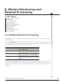
Motion Error . . . . . . . . . . . . . . . . . . . . . . . . . . . . . . . . . . . . . . . . . . . . . . . . . . . . . . . . . . 59
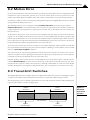
Travel-limit Switches . . . . . . . . . . . . . . . . . . . . . . . . . . . . . . . . . . . . . . . . . . . . . . . . . . 59
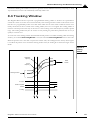
Tracking Window . . . . . . . . . . . . . . . . . . . . . . . . . . . . . . . . . . . . . . . . . . . . . . . . . . . . . 61
Motion Complete Indicator . . . . . . . . . . . . . . . . . . . . . . . . . . . . . . . . . . . . . . . . . . . . 62
In-motion Indicator . . . . . . . . . . . . . . . . . . . . . . . . . . . . . . . . . . . . . . . . . . . . . . . . . . . 63
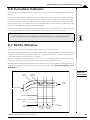
Settle Window . . . . . . . . . . . . . . . . . . . . . . . . . . . . . . . . . . . . . . . . . . . . . . . . . . . . . . . . 63
Trace Capture . . . . . . . . . . . . . . . . . . . . . . . . . . . . . . . . . . . . . . . . . . . . . . . . . . . . . . . . . 64
Trace Buffer Architecture . . . . . . . . . . . . . . . . . . . . . . . . . . . . . . . . . . . . . . . . . . . . . . 64
Host Interrupts . . . . . . . . . . . . . . . . . . . . . . . . . . . . . . . . . . . . . . . . . . . . . . . . . . . . . . . . 69
9. Hardware Control Signals . . . . . . . . . . . . . . . . . . . . . . . . . . . . . . . . . . . . . 73
9.1
9.2
9.3
9.4
The AxisOut Pin . . . . . . . . . . . . . . . . . . . . . . . . . . . . . . . . . . . . . . . . . . . . . . . . . . . . . . . 73
The AxisIn Pin . . . . . . . . . . . . . . . . . . . . . . . . . . . . . . . . . . . . . . . . . . . . . . . . . . . . . . . . . 73
Analog Input . . . . . . . . . . . . . . . . . . . . . . . . . . . . . . . . . . . . . . . . . . . . . . . . . . . . . . . . . . 74
The Synch Pin—Multiple Chip Synchronization . . . . . . . . . . . . . . . . . . . . . . . . 74
10. Encoder Interfacing . . . . . . . . . . . . . . . . . . . . . . . . . . . . . . . . . . . . . . . . . 77
10.1
10.2
10.3
Incremental Encoder Input . . . . . . . . . . . . . . . . . . . . . . . . . . . . . . . . . . . . . . . . . . . . 77
High-speed Position Capture . . . . . . . . . . . . . . . . . . . . . . . . . . . . . . . . . . . . . . . . . . 78
Parallel-word Position Input . . . . . . . . . . . . . . . . . . . . . . . . . . . . . . . . . . . . . . . . . . . 79
11. Motor Output . . . . . . . . . . . . . . . . . . . . . . . . . . . . . . . . . . . . . . . . . . . . . . . 81
11.1
11.2
11.3
11.4
11.5
11.6
11.7
11.8
Disabling the Motor Output Module . . . . . . . . . . . . . . . . . . . . . . . . . . . . . . . . . . . 81
Enabling the Motor Output Module . . . . . . . . . . . . . . . . . . . . . . . . . . . . . . . . . . . . 82
Motor Type . . . . . . . . . . . . . . . . . . . . . . . . . . . . . . . . . . . . . . . . . . . . . . . . . . . . . . . . . . . 82
Motor Command Output . . . . . . . . . . . . . . . . . . . . . . . . . . . . . . . . . . . . . . . . . . . . . . 83
Setting PWM Frequency . . . . . . . . . . . . . . . . . . . . . . . . . . . . . . . . . . . . . . . . . . . . . . . 87
Multi-Phase Motor Interfacing . . . . . . . . . . . . . . . . . . . . . . . . . . . . . . . . . . . . . . . . . 87
Pulse & Direction Signal Generation . . . . . . . . . . . . . . . . . . . . . . . . . . . . . . . . . . . 89
Microstepping Motor Output . . . . . . . . . . . . . . . . . . . . . . . . . . . . . . . . . . . . . . . . . . 91
12. Host Communication . . . . . . . . . . . . . . . . . . . . . . . . . . . . . . . . . . . . . . . . 95
12.1
12.2
12.3
12.4
12.5
Host I/O Commands . . . . . . . . . . . . . . . . . . . . . . . . . . . . . . . . . . . . . . . . . . . . . . . . . . . 96
Parallel Communication Port . . . . . . . . . . . . . . . . . . . . . . . . . . . . . . . . . . . . . . . . . . 97
Serial Port . . . . . . . . . . . . . . . . . . . . . . . . . . . . . . . . . . . . . . . . . . . . . . . . . . . . . . . . . . . .100
Controller Area Network (CAN) . . . . . . . . . . . . . . . . . . . . . . . . . . . . . . . . . . . . . . .104
Storing Communication Values . . . . . . . . . . . . . . . . . . . . . . . . . . . . . . . . . . . . . . .107
13. Brushless DC Motor Control . . . . . . . . . . . . . . . . . . . . . . . . . . . . . . . . . 109
13.1
13.2
13.3
13.4
13.5
13.6
13.7
13.8
13.9
13.10
Overview . . . . . . . . . . . . . . . . . . . . . . . . . . . . . . . . . . . . . . . . . . . . . . . . . . . . . . . . . . . .109
Number of Phases . . . . . . . . . . . . . . . . . . . . . . . . . . . . . . . . . . . . . . . . . . . . . . . . . . . .110
Phasing Control Modes . . . . . . . . . . . . . . . . . . . . . . . . . . . . . . . . . . . . . . . . . . . . . . .110
Phase Counts . . . . . . . . . . . . . . . . . . . . . . . . . . . . . . . . . . . . . . . . . . . . . . . . . . . . . . . .111
Phase Initialization . . . . . . . . . . . . . . . . . . . . . . . . . . . . . . . . . . . . . . . . . . . . . . . . . . .111
Phase Initialization Programming . . . . . . . . . . . . . . . . . . . . . . . . . . . . . . . . . . . . .113
Index Pulse Referencing . . . . . . . . . . . . . . . . . . . . . . . . . . . . . . . . . . . . . . . . . . . . . .114
Encoder Prescaler . . . . . . . . . . . . . . . . . . . . . . . . . . . . . . . . . . . . . . . . . . . . . . . . . . . .116
Sinusoidal Commutation . . . . . . . . . . . . . . . . . . . . . . . . . . . . . . . . . . . . . . . . . . . . .116
Field Oriented Control . . . . . . . . . . . . . . . . . . . . . . . . . . . . . . . . . . . . . . . . . . . . . . . .117
14. Step Motor Control . . . . . . . . . . . . . . . . . . . . . . . . . . . . . . . . . . . . . . . . . 121
14.1
14.2
A*
Overview . . . . . . . . . . . . . . . . . . . . . . . . . . . . . . . . . . . . . . . . . . . . . . . . . . . . . . . . . . . .121
Encoder Feedback . . . . . . . . . . . . . . . . . . . . . . . . . . . . . . . . . . . . . . . . . . . . . . . . . . .122
Magellan'Motion Processor User’s Guide
7"D%$+(>+9(&)$&)/
14.3
14.4
14.5
Stall Detection . . . . . . . . . . . . . . . . . . . . . . . . . . . . . . . . . . . . . . . . . . . . . . . . . . . . . . 122
Pulse & Direction Motor Control . . . . . . . . . . . . . . . . . . . . . . . . . . . . . . . . . . . . . 123
Microstepping Motor Control . . . . . . . . . . . . . . . . . . . . . . . . . . . . . . . . . . . . . . . . 124
15. Drive Control . . . . . . . . . . . . . . . . . . . . . . . . . . . . . . . . . . . . . . . . . . . . . . . 127
15.1
15.2
15.3
15.4
15.5
15.6
15.7
15.8
15.9
15.10
15.11
15.12
15.13
Current Loop . . . . . . . . . . . . . . . . . . . . . . . . . . . . . . . . . . . . . . . . . . . . . . . . . . . . . . . . 127
Current Loop Parameters . . . . . . . . . . . . . . . . . . . . . . . . . . . . . . . . . . . . . . . . . . . . 128
Enabling and Disabling Current Loop . . . . . . . . . . . . . . . . . . . . . . . . . . . . . . . . 129
Reading Current Loop Values . . . . . . . . . . . . . . . . . . . . . . . . . . . . . . . . . . . . . . . . 129
Drive Control Features . . . . . . . . . . . . . . . . . . . . . . . . . . . . . . . . . . . . . . . . . . . . . . . 130
Electrical Faults . . . . . . . . . . . . . . . . . . . . . . . . . . . . . . . . . . . . . . . . . . . . . . . . . . . . . . 130
Drive Fault Status Register . . . . . . . . . . . . . . . . . . . . . . . . . . . . . . . . . . . . . . . . . . . 131
FaultOut Signal . . . . . . . . . . . . . . . . . . . . . . . . . . . . . . . . . . . . . . . . . . . . . . . . . . . . . . 131
Overtemperature Sense . . . . . . . . . . . . . . . . . . . . . . . . . . . . . . . . . . . . . . . . . . . . . 132
Overvoltage Sense . . . . . . . . . . . . . . . . . . . . . . . . . . . . . . . . . . . . . . . . . . . . . . . . . . 132
Undervoltage Sense . . . . . . . . . . . . . . . . . . . . . . . . . . . . . . . . . . . . . . . . . . . . . . . . . 133
Drive Enable . . . . . . . . . . . . . . . . . . . . . . . . . . . . . . . . . . . . . . . . . . . . . . . . . . . . . . . . 133
Current Foldback . . . . . . . . . . . . . . . . . . . . . . . . . . . . . . . . . . . . . . . . . . . . . . . . . . . . 134
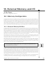
16. External Memory and I/O . . . . . . . . . . . . . . . . . . . . . . . . . . . . . . . . . . . . 137
16.1
16.2
Memory Configuration . . . . . . . . . . . . . . . . . . . . . . . . . . . . . . . . . . . . . . . . . . . . . . 137
User I/O . . . . . . . . . . . . . . . . . . . . . . . . . . . . . . . . . . . . . . . . . . . . . . . . . . . . . . . . . . . . . 139
Index . . . . . . . . . . . . . . . . . . . . . . . . . . . . . . . . . . . . . . . . . . . . . . . . . . . . . . . . . . 141
Magellan'Motion Processor User’s Guide
A**
7"D%$+(>+9(&)$&)/
This page intentionally left blank.
A***
Magellan'Motion Processor User’s Guide
F*/)+(>+G*#3-$/
2"1
3"1
4"1
4"2
4"3
4"4
4"5
4"6
4"7
4"8
4"9
5"1
5"2
5"3
5"4
5"5
5"6
8"1
8"2
8"3
10"1
11"1
11"2
11"3
11"4
11"5
11"6
11"7
11"8
11"9
11"10
12"1
12"2
13"1
13"2
13"3
13"4
13"5
14"1
14"2
15"1
Magellan system block diagram 6 6 6 6 6 6 6 6 6 6 6 6 6 6 6 6 6 6 6 6 6 6 6 6 6 6 6 6 6 6 6 6 6 6 6 6 6 6 6 6 6 6 6 6 6 613
Magellan internal block diagram 6 6 6 6 6 6 6 6 6 6 6 6 6 6 6 6 6 6 6 6 6 6 6 6 6 6 6 6 6 6 6 6 6 6 6 6 6 6 6 6 6 6 6 6 617
Simple trapezoidal point"to"point profiles 6 6 6 6 6 6 6 6 6 6 6 6 6 6 6 6 6 6 6 6 6 6 6 6 6 6 6 6 6 6 6 6 6 6 6 6 624
Trapezoidal profile with non"zero starting velocity 6 6 6 6 6 6 6 6 6 6 6 6 6 6 6 6 6 6 6 6 6 6 6 6 6 6 6 6 6 625
Simple trapezoidal point"to"point profile 6 6 6 6 6 6 6 6 6 6 6 6 6 6 6 6 6 6 6 6 6 6 6 6 6 6 6 6 6 6 6 6 6 6 6 6 6 625
Complex trapezoidal point"to"point profileE showing parameter changes 6 6 6 6 6 6 6 6 6 6 6 626
Typical S"curve point"to"point profile 6 6 6 6 6 6 6 6 6 6 6 6 6 6 6 6 6 6 6 6 6 6 6 6 6 6 6 6 6 6 6 6 6 6 6 6 6 6 6 6 627
S"curve that does not reach maximum acceleration 6 6 6 6 6 6 6 6 6 6 6 6 6 6 6 6 6 6 6 6 6 6 6 6 6 6 6 6 627
S"curve with no maximum"velocity segment 6 6 6 6 6 6 6 6 6 6 6 6 6 6 6 6 6 6 6 6 6 6 6 6 6 6 6 6 6 6 6 6 6 6 628
Velocity"contouring profile 6 6 6 6 6 6 6 6 6 6 6 6 6 6 6 6 6 6 6 6 6 6 6 6 6 6 6 6 6 6 6 6 6 6 6 6 6 6 6 6 6 6 6 6 6 6 6 6 629
Electronic gear profile 6 6 6 6 6 6 6 6 6 6 6 6 6 6 6 6 6 6 6 6 6 6 6 6 6 6 6 6 6 6 6 6 6 6 6 6 6 6 6 6 6 6 6 6 6 6 6 6 6 6 6 6 630
PID loop and biquad filters 6 6 6 6 6 6 6 6 6 6 6 6 6 6 6 6 6 6 6 6 6 6 6 6 6 6 6 6 6 6 6 6 6 6 6 6 6 6 6 6 6 6 6 6 6 6 6 6 633
Position loop flow 6 6 6 6 6 6 6 6 6 6 6 6 6 6 6 6 6 6 6 6 6 6 6 6 6 6 6 6 6 6 6 6 6 6 6 6 6 6 6 6 6 6 6 6 6 6 6 6 6 6 6 6 6 6 6 634
Magellan dual"loop flow 6 6 6 6 6 6 6 6 6 6 6 6 6 6 6 6 6 6 6 6 6 6 6 6 6 6 6 6 6 6 6 6 6 6 6 6 6 6 6 6 6 6 6 6 6 6 6 6 6 6 6 636
Magellan dual"loop digital filter 6 6 6 6 6 6 6 6 6 6 6 6 6 6 6 6 6 6 6 6 6 6 6 6 6 6 6 6 6 6 6 6 6 6 6 6 6 6 6 6 6 6 6 6 6 637
Biquad algorithm flow 6 6 6 6 6 6 6 6 6 6 6 6 6 6 6 6 6 6 6 6 6 6 6 6 6 6 6 6 6 6 6 6 6 6 6 6 6 6 6 6 6 6 6 6 6 6 6 6 6 6 6 6 638
Motor control pathsE trajectory enabled/disabled 6 6 6 6 6 6 6 6 6 6 6 6 6 6 6 6 6 6 6 6 6 6 6 6 6 6 6 6 6 6 642
Directional limit switch operation 6 6 6 6 6 6 6 6 6 6 6 6 6 6 6 6 6 6 6 6 6 6 6 6 6 6 6 6 6 6 6 6 6 6 6 6 6 6 6 6 6 6 659
Tracking window 6 6 6 6 6 6 6 6 6 6 6 6 6 6 6 6 6 6 6 6 6 6 6 6 6 6 6 6 6 6 6 6 6 6 6 6 6 6 6 6 6 6 6 6 6 6 6 6 6 6 6 6 6 6 6 6 661
Settle window 6 6 6 6 6 6 6 6 6 6 6 6 6 6 6 6 6 6 6 6 6 6 6 6 6 6 6 6 6 6 6 6 6 6 6 6 6 6 6 6 6 6 6 6 6 6 6 6 6 6 6 6 6 6 6 6 6 6 663
Tuadrature encoder timing 6 6 6 6 6 6 6 6 6 6 6 6 6 6 6 6 6 6 6 6 6 6 6 6 6 6 6 6 6 6 6 6 6 6 6 6 6 6 6 6 6 6 6 6 6 6 6 677
50/50 PWM encoding 6 6 6 6 6 6 6 6 6 6 6 6 6 6 6 6 6 6 6 6 6 6 6 6 6 6 6 6 6 6 6 6 6 6 6 6 6 6 6 6 6 6 6 6 6 6 6 6 6 6 6 6 685
Brushless motor VPWM modeW connection scheme 6 6 6 6 6 6 6 6 6 6 6 6 6 6 6 6 6 6 6 6 6 6 6 6 6 6 6 6 688
Brushless motor VDAC modeW connection scheme 6 6 6 6 6 6 6 6 6 6 6 6 6 6 6 6 6 6 6 6 6 6 6 6 6 6 6 6 6 688
Motor output waveform VVoutW 6 6 6 6 6 6 6 6 6 6 6 6 6 6 6 6 6 6 6 6 6 6 6 6 6 6 6 6 6 6 6 6 6 6 6 6 6 6 6 6 6 6 6 6 689
Step motor connection 6 6 6 6 6 6 6 6 6 6 6 6 6 6 6 6 6 6 6 6 6 6 6 6 6 6 6 6 6 6 6 6 6 6 6 6 6 6 6 6 6 6 6 6 6 6 6 6 6 6 6 690
Typical motor output waveform 6 6 6 6 6 6 6 6 6 6 6 6 6 6 6 6 6 6 6 6 6 6 6 6 6 6 6 6 6 6 6 6 6 6 6 6 6 6 6 6 6 6 6 6 691
Filtered PWM sign/magnitude waveform 6 6 6 6 6 6 6 6 6 6 6 6 6 6 6 6 6 6 6 6 6 6 6 6 6 6 6 6 6 6 6 6 6 6 6 6 6 692
Typical amplifier configuration for 2"phase motor 6 6 6 6 6 6 6 6 6 6 6 6 6 6 6 6 6 6 6 6 6 6 6 6 6 6 6 6 6 6 692
Typical amplifier current"control configuration 6 6 6 6 6 6 6 6 6 6 6 6 6 6 6 6 6 6 6 6 6 6 6 6 6 6 6 6 6 6 6 6 693
Typical amplifier configuration for 3"phase motor 6 6 6 6 6 6 6 6 6 6 6 6 6 6 6 6 6 6 6 6 6 6 6 6 6 6 6 6 6 6 694
Host to motion processor communications 6 6 6 6 6 6 6 6 6 6 6 6 6 6 6 6 6 6 6 6 6 6 6 6 6 6 6 6 6 6 6 6 6 6 6 695
Typical data frame format 6 6 6 6 6 6 6 6 6 6 6 6 6 6 6 6 6 6 6 6 6 6 6 6 6 6 6 6 6 6 6 6 6 6 6 6 6 6 6 6 6 6 6 6 6 6 6 6 6101
Commutation waveforms 6 6 6 6 6 6 6 6 6 6 6 6 6 6 6 6 6 6 6 6 6 6 6 6 6 6 6 6 6 6 6 6 6 6 6 6 6 6 6 6 6 6 6 6 6 6 6 6 6110
Hall"based phase initialization 6 6 6 6 6 6 6 6 6 6 6 6 6 6 6 6 6 6 6 6 6 6 6 6 6 6 6 6 6 6 6 6 6 6 6 6 6 6 6 6 6 6 6 6 6 6112
Sinusoidal commutation 6 6 6 6 6 6 6 6 6 6 6 6 6 6 6 6 6 6 6 6 6 6 6 6 6 6 6 6 6 6 6 6 6 6 6 6 6 6 6 6 6 6 6 6 6 6 6 6 6 6117
Control flow of FOC control 6 6 6 6 6 6 6 6 6 6 6 6 6 6 6 6 6 6 6 6 6 6 6 6 6 6 6 6 6 6 6 6 6 6 6 6 6 6 6 6 6 6 6 6 6 6118
Algorithmic flow of FOC controller 6 6 6 6 6 6 6 6 6 6 6 6 6 6 6 6 6 6 6 6 6 6 6 6 6 6 6 6 6 6 6 6 6 6 6 6 6 6 6 6 6119
Microstepping waveform generation 6 6 6 6 6 6 6 6 6 6 6 6 6 6 6 6 6 6 6 6 6 6 6 6 6 6 6 6 6 6 6 6 6 6 6 6 6 6 6 6 6124
Microstepping waveforms 6 6 6 6 6 6 6 6 6 6 6 6 6 6 6 6 6 6 6 6 6 6 6 6 6 6 6 6 6 6 6 6 6 6 6 6 6 6 6 6 6 6 6 6 6 6 6 6 6125
Current loop control flow 6 6 6 6 6 6 6 6 6 6 6 6 6 6 6 6 6 6 6 6 6 6 6 6 6 6 6 6 6 6 6 6 6 6 6 6 6 6 6 6 6 6 6 6 6 6 6 6128
Magellan'Motion Processor User’s Guide
*E
F*/)+(>+G*#3-$/
This page intentionally left blank.
E
Magellan'Motion Processor User’s Guide
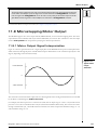
1I+7C$+!"#$%%"&+G"@*%<
1
In This Chapter
!"Family Summary
!"Magellan Motion Processor Products
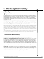
The Magellan Motion Processor User’s Guide supports the Magellan'Family of Motion Processors from PMD, including the
MC58000 Series (DC brush, brushless DC, microstepping, and step motor), the MC55000 Series (step motor), and the
Magellan/ION Motion Processor. In addition, Magellan processors are used in a number of card-level products,
including the Prodigy-PCI and Prodigy-PC/104 cards; the exact motion processor type can be determined from the
corresponding user’s guide.
Each Magellan is a complete chip-based motion processor, providing trajectory generation and related motion control
functions. Depending on the type of motor to be controlled, it provides servo loop closure, on-board commutation for
brushless motors, and high-speed pulse and direction outputs. Together, these products provide a software-compatible
family of dedicated motion processors that can handle a large variety of system configurations.
Each of the multi-chip versions of these products utilize a similar architecture, consisting of a high-speed computation
unit along with an ASIC (Application Specific Integrated Circuit). The computation unit contains special on-board
hardware that makes it well suited for the task of motion control. Single-axis/single-chip configurations of Magellan are
also available. In these products the logic provided in the ASIC is integrated directly with the high-speed computation
unit.
Along with similar hardware architecture, these chips also share most software commands. Therefore, software written
for one motion processor may be used with another, independent of motor type or hardware configuration.
1I1+G"@*%<+=3@@"-<
The various members of the Magellan family are designed for different motor types and applications:
MC5JEEE Series (MC5J42E, MC5JN2E, MC5J22E, MC5JD2E, MC5JDDE) - This series supports DC brush, brushless
DC, and step motors using both pulse and direction and microstepping output formats. For use with DC brush or
brushless DC with external commutation, it outputs in PWM or DAC-compatible format. With two-phase or threephase brushless DC motors it outputs in PWM or DAC-compatible format. With pulse and direction step motors it
outputs in pulse and direction format, and with microstepping step motors it outputs PWM or DAC-compatible format.
MC55EEE Series (MC5542E, MC55N2E, MC5522E, MC55D2E, MC55DDE) - This series outputs pulse and direction
signals for use with step motors.
Magellan/ION - This single-chip motion processor is specifically designed to work with the ION family of digital
drives. It provides one axis of control, with an additional auxiliary axis of encoder input. It controls either a DC brush
motor, a three-phase brushless DC motor, or a step motor. Compared to the MC50000, it has additional amplifier
control features such as digital current control and overtemperature sense. The Magellan/ION is only available
embedded in the ION Digital Drive; it is not sold as a separate motion processor device.
Magellan'Motion Processor User’s Guide
11
1
7C$+!"#$%%"&+G"@*%<
1I2+!"#$%%"&+!()*(&+,-(.$//(-+,-(43.)/
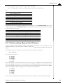
The following table presents a feature summary of the products in the Magellan Motion Processor product family:
\ of axes
Motor types supported
Output format
Parallel communication
Serial communication
CAN 260B communication
Incremental encoder input
Parallel word device input
Index & Home signals
Position capture
Directional limit switches
PWM output
Parallel DAC output
SPI DAC output
Pulse & direction output
Digital current control
Field oriented control
Under/overvoltage sense
12T Current foldback
Trapezoidal profiling
Velocity profiling
S"curve profiling
Electronic gearing
On"the"fly changes
PID position servo loop
Dual biquad filters
Dual encoder loop
Programmable derivative
sampling time
Feedforward Vaccel & velW
Data trace/diagnostics
Motion error detection
Axis settled indicator
Analog input
Programmable bit output
Software"invertible signals
User"defined I/O
External RAM support
Multi"chip synchronization
Chipset configurations
Motion processor devel"
operas kit p/nas
12
!95LMMM+=$-*$/
1E 2E 3E 4
!955MMM+=$-*$/
1E 2E 3E 4
DC brushE brushless DCE
step motor
Step motor
PWME DACE Pulse & direction
!
!
!
!
!
!
!
!
!
!
!
!
!
!
!
!
!
!
!
!
Vmulti"axis configurations onlyW
Pulse & direction
!
!
!
!
!
!
!
!
!
!
!
!
!
!
!
!
MC58420 V4 axesE 2 ICsW
MC58320 V3 axesE 2 ICsW
MC58220 V2 axesE 2 ICsW
MC58120 V1 axisE 2 ICsW
MC58110 V1 axisE 1 ICW
Db58420 V4 axesE 2 ICsW
Db58110 V1axisE 1 ICW
!
!
!
!
!
!
amplifier is internal
!
!
!
!
!
!
!
!
!
!
!
!
!
!
!
brushed or brushless only
!
!
!
!
!
!"#$%%"&N865
1
DC brushE
brushless DCE
step motor
PWM Vinternal to driveW
!
!
!
Vrequires encoderW
!
Vrequires encoderW
!
!
!
!
!
MC55420 V4 axesE 2 ICsW
MC55320 V3 axesE 2 ICsW
MC55220 V2 axesE 2 ICsW
MC55120 V1 axisE 2 ICsW
MC55110 V1 axisE 1 ICW
Db55420 V4 axesE 2 ICsW
Db55110 V1 axisE 1 ICW
!
!
!
!
!
!
Magellan/ION sold as part of
ION drive only6
Not available as motion pro"
cessor developeras kit6 Used
exclusively in ION digital
drive products6
Magellan'Motion Processor User’s Guide
2I+=</)$@+6A$-A*$P
2
In This Chapter
!"Documentation Guide
!"Product P/N Referencing Guide
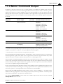
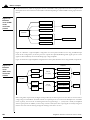
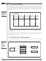
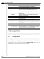
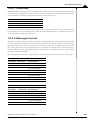
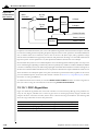
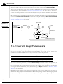
#igure 2*1+
Magellan
system 4loc7
diagram
CANOpen=CAN ).0> network
Aerial Network
1C or DECbit Parallel Port
Motor
amplifier
Parallel word input
Parallel
D6A
converter
Current A,B
(Magellan/ION only)
Positive
AxisIn
Limit
switches
Analog inputs
CANbus configuration
Negative
Aerial configuration
Serial
D6A
converter
Hall A,B,C
Motor configuration
@ABbit data bus
PWM or Pulse ? Direction output
Home
B
Index
A
-n,/)$%
AxisOut
Magellan Motion Processor
Aystem clock
H+0 MJKL
API
Host
External memory
DAC
output
User I6O
!"#$%&'($%&)$*+,$(
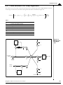
Figure 2-1 shows an interconnection diagram for the Magellan Motion Processor. For chip-level designs, you will
interface these interconnections with your own circuitry to create a complete motion card. For Magellan-based card and
module-level products, some of these connections (such as encoder, limit switches, etc.) are available externally to the
user, while some are connected to the internal card or module circuitry and do not require user interfacing. Refer to the
card user’s guide or module user’s manual for more information.
Regardless of the hardware configuration, the overall control approach is similar. Each axis inputs the actual location of
the axis using either incremental encoder signals or a parallel-word input device such as an absolute encoder, analog-todigital converter, resolver, or laser interferometer. If incremental signals are used, the incoming A and B quadrature data
stream is digitally filtered, and then passed on to a high-speed up/down counter. Using the parallel-word interface, a
direct binary-encoded position of up to 16 bits is read by the motion processor. Regardless of the encoder input method,
this position information is then used to maintain a 32-bit actual axis position counter.
Magellan contains a trajectory generator that calculates a new desired position at each cycle time interval, which is based
on the profile modes and parameters programmed by the host, as well as on the current state of the system. The cycle
time is the rate at which major system parameters (such as trajectory, servo compensation [if using the MC58000 or
Magellan/ION]) and other motion processor functions are updated.
For motion processors with servo motor support (MC58000, Magellan/ION), the output of the trajectory generator is
combined with the actual encoder position to calculate a 32-bit position error, which is passed through a PID position
loop.
Magellan'Motion Processor User’s Guide
13
2
=</)$@+6A$-A*$P
The resultant value is then output by the motion processor to an external amplifier using either PWM or DAC signals.
If the axis is configured for a brushless DC motor, then the output signals are commutated, meaning they are
combined with information about the motor phase angle to distribute the desired motor torque to two- or threephased output commands.
With an MC58000 axis configured for DC brush servo motors, the single-phase motor command is output directly.
For axes configured for step motors, the output of the trajectory generator is converted to either microstepping signals
(MC58000, Magellan/ION only), or pulse and direction signals, and is then output accordingly. Microstepping signals
are output in either PWM or DAC format.
For Magellan/ION, all motor output formats are utilized internally by the drive. In addition, ION provides a capability
for digital current or field oriented control, along with numerous monitoring and control features.
Current Loop and FOC are available only on Magellan/ION6
Communication to and from Magellan Motion Processors is accomplished using a parallel-bus interface, an
asynchronous serial port, or a CAN 2.0B interface. If parallel-bus communication is used, there is a further choice of
8-bit wide transfers or 16-bit wide transfers, allowing a range of microprocessors and data buses to be interfaced. If
serial communications are used, then the user selects parameters such as baud rate, number of stop/start bits, and the
transfer protocol. The transfer protocol may be either point-to-point (appropriate for single-motion processor
systems), or multi-drop (appropriate for serial communications to multiple motion processors). For CAN
communication, the user selects the desired CAN data bus rate and the CAN node address.
For card-product communications through the bus, the parallel-bus interface is fixed to a 16-bit format. For example,
the Prodigy-PCI card provides a complete PCI bus interface that connects on the card to the motion processor in its
16-bit parallel interface mode. PMD’s motion cards also provide serial and CANbus communication options.
Magellan/ION does not provide a parallel interface mode; it has serial or CANbus communications only.
Regardless of the hardware interface method, communication to and from Magellan Motion Processors occurs using
short commands sent or received as a sequence of bytes and words. These packets contain an instruction code word
that tells the motion processor which operation is being requested. It may also contain data sent to, or received from,
the motion processor.
These commands are sent by a host microprocessor or host computer executing a supervisor program that provides
overall system control. The Magellan Motion Processor is designed to function as the motion engine, managing highspeed dedicated motion functions such as trajectory generation, safety monitoring, etc., while the host software program provides the overall motion sequences.
2I1+?(.3@$&)")*(&+23*4$
Many functions are common across all Magellan Motion Processors. However, some sections of this user’s guide
describe features that apply to specific motor types, or to certain Magellan products. For example, servo filtering
applies only to axes configured for DC brush or brushless DC motors. The following table cross-references the
applicable chapters for each motor type and Magellan-based product.
14
Magellan'Motion Processor User’s Guide
=</)$@+6A$-A*$P
2
!"#$$$$%&e()e*%!+,)+-%.(+/e**+(*
The following table describes the MC50000 Series Motion Processors.
!()(-+7<R$
DC brush
Brushless DC
V2 phaseE 3 phaseW
Microstepping motor
Pulse & direction step
motor
?$/.-*R)*(&
SRR%*."D%$+9C"R)$-/
Servo motors with internal mechanical commutationE or 1d12E 16
connected to a commutating amplifier6
Servo motors requiring external electrical commutation6 1d13E 16
Step motor with microstepping drive6
Step motor with pulse & direction drive6
1d4E 6d12E 14E 16
1d4E 6d12E 14E 16
!01e220-3456%!+,)+-%.(+/e**+(*
The following table describes the Magellan/ION Motion Processors.
!()(-+7<R$
DC brush
Brushless DC
Step motor
?$/.-*R)*(&
Servo motors with internal mechanical commutation6
3"phase brushless DC servo motors6
2"phase step motor6
SRR%*."D%$+9C"R)$-/
1d12E 15
1d13E 15
1d12E 14E 15
2I2+,-(43.)+,N5+B$>$-$&.*&#+23*4$
Various chapters, sections, or paragraphs give descriptions such as “MC55000 only.” The following table indicates the
specific products that are referred to by each such reference.
B$>$-$&.$
MC58000
MC55000
MC50000
Magellan/ION
?$/.-*R)*(&
Indicates all MC58000 series Magellan Motion Processors6
,"-)/+8&.%34$4
MC58420
MC58320
MC58220
MC58120
MC58110
Indicates all MC55000 series Magellan Motion Processors6
MC55420
MC55320
MC55220
MC55120
MC55110
Indicates all Magellan Motion Processors except Magellan/ION6
MC58420
MC58320
MC58220
MC58120
MC58110
MC55420
MC55320
MC55220
MC55120
MC55110
Indicates all Magellan Motion Processors for the ION product familyE Not sold as separate
DC brushE brushless DCE and step motor6
motion processor6 Refer
to the !"#$%&'&()*$%+&,e$
.se+0s$1)23)* for a list of
ION digital drive product
numbers6
Magellan'Motion Processor User’s Guide
15
2
=</)$@+6A$-A*$P
This page intentionally left blank.
1T
Magellan'Motion Processor User’s Guide
3I+9(&)-(%+!(43%$/
3
In This Chapter
!"Control Flow Overview
!"Enabling and Disabling Control Modules
!"Reset Command
!"Setting the Cycle Time
!"The Time Register
!"GetVersion Command
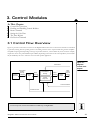
3I1+9(&)-(%+G%(P+6A$-A*$P
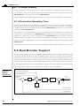
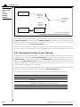
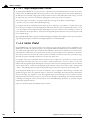
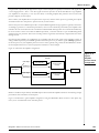
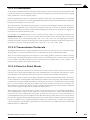
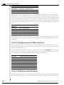
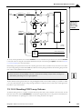
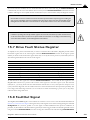
Figure 3-1 provides a control flow overview for the Magellan Motion Processors. It shows how a final motor command
is generated, starting with the profile generator and ending with the motor output module that generates amplifiercompatible output signals. Depending on the type of product and motor, some modules may not be used. For example,
step motors do not use a position PID loop. In addition, depending on the nature of the control problem, some modules
may be disabled by the user to tailor the control for their specific application.
#igure 3*1+
Magellan
internal 4loc7
diagram
Jall Aensors
Trajectory
Tenerator
Commanded
Position,
Yelocity,
Acceleration
Position
Loop
Motor
Command
Commutation=
Phasing
Phase
Command
Motor
Output
PVM
or DAC
output to
amplifier
Current
Loop= UOC
Current Ueedback
Position Wncoder
Current LoopE FOCE and Current Feedback are available only on Magellan/ION6
Magellan'Motion Processor User’s Guide
17
3
9(&)-(%+!(43%$/
Each of the major blocks within the control flow diagram is referred to as a module. The following table provides a
brief description of each module.
!(43%$+5"@$
Trajectory Generator
Position Loop
Commutation/Phasing
Current Loop/FOC
Motor Output
G3&.)*(&
This module accepts user"specified parameters and generates a trajectory6
This module is used with servo motors only6 It inputs the 4566)27e7$85s&(&52 Vthe
instantaneous desired axis positionW and the )4(3)*$85s&(&52 Vthe motor position mea"
sured by an encoderWE and passes the resultant 85s&(&52$e++5+ Vthe difference between the
commanded and the actual positionW through a PID filter along with dual biquad filters
to generate a motor command6
This module is used with multi"phase motors such as brushless DC motors or micro"
stepping step motorsE and generates desired torque signals for each phase of the motor6
This module is used with Magellan/ION only6 It inputs the desired torque for each
motor phase along with the actual measured current through each phaseE and passes
the resultant difference through a PI filter to generate a motor command6
This module inputs the desired motor phase command and generates the appropriate
signals for the selected output format6
Each of these modules is described in detail in subsequent chapters. Beyond the functions provided by these major
control modules, Magellan also provides numerous additional capabilities such as breakpoints, trace, and PLC-style
signal control. These features are common to all motor types and motion processors, and are also described in detail
in subsequent chapters.
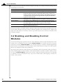
3I2+:&"D%*&#+"&4+?*/"D%*&#+9(&)-(%+
!(43%$/
At various times during setup or operation of an axis, it may be desirable to selectively enable or disable specific control
modules. This is accomplished using the command SetOperatingMode. To read back the status set using this
command, the command GetOperatingMode is used. Generally speaking, if a module is disabled, Magellan skips
whatever features and calculations are associated with that module, and the input from the previous module is passed
directly to the subsequent module without modification.
The following table summarizes which modules may be disabled or enabled, and describes typical circumstances
under which this might be useful. In addition to these specific modules it is possible to enable or disable an entire
axis using the SetOperatingMode command. Note that the commutation/phasing module may not be disabled
or enabled by the user. If a multi-phase motor type such as brushless DC or microstepping is selected, this
module is always enabled.
1L
Magellan'Motion Processor User’s Guide
9(&)-(%+!(43%$/
!(43%$
Trajectory Generator
Position Loop
Current Loop
VMagellan/ION onlyW
Motor Output
3
?$/.-*R)*(&
7<R*."%+0/$/
If disabledE the commanded position will stay The trajectory generator is not usually dis"
at its present value6
abled manually6 For trajectory controlE
which requires an immediate stopE the
SetStopMode command with an argu"
ment of Abrupt Stop is used instead6
Used with servo motors only6 If disabledE this Disabling this module with trajectory gen"
module outputs from one of two sourcesE
erator enabled is useful if voltage or
depending on whether the trajectory genera" current"proportional positioning devices
tor module is enabled or disabled6
are usedE such as certain kinds of galvanom"
9+):e4(5+;$'e2e+)(5+$e2)<*e7= If the trajectory
eters6 It may also be useful if amplifier cali"
generator is enabledE then the position loop is bration with automated ramps is required6
skippedE and the output of the profile generator With trajectory generator disabledE
is input directly to the subsequent module6
disabling this module may be useful for
9+):e4(5+;$'e2e+)(5+$7&s)<*e7=$If the trajectory amplifier or motor calibration6
generator is also disabledE the output comes
from the Motor Command registerE which
can be manually set using the command
SetMotorCommand6
See Section 566E %&s)<*&2'$)27$>2)<*&2'$(?e$@5s&A
(&52$B558$1573*e for more information6
If this module is disabledE the input motor
Disabling the current loop is useful when
command will be passed unmodified to the
you are using an external amplifier that
motor output module6
already provides torque or velocity"based
control6
Disabling this module sets all motor genera" Disabling motor output is useful in connec"
tion to a value of zero V0W6 The actual states tion with various safety"related conditionsE
of the associated motor output signals will
or for amplifier calibration6
depend on the selected signalling method
VPWM sign/magE PWM 50/50E parallel DACE
or serial DACW See Section 1164E 15(5+$C56A
6)27$"3(83( for more information6
In addition to manually disabling modules, there are a number of circumstances where modules may be automatically
disabled due to event-related issues, or breakpoints. See Section 8.1, SetEventAction Processing and Section 6.2,
Breakpoints for more information.
GetOperatingMode returns the value set using the command SetOperatingMode, which sets the desired operating
mode under normal operational circumstances. However this may differ from the actual operating mode for the
reasons mentioned above. To determine the actual current status of the operating mode word use the
GetActiveOperatingMode command.
This useras guide includes various command mnemonics to clarify motion process or command usage or provide
specific examples6 See the 1)'e**)2$15(&52$@+54ess5+$@+5'+)66e+0s$C566)27$DeEe+e24e for more information on
host commandsE nomenclatureE and syntax6
Magellan'Motion Processor User’s Guide
1V
3
9(&)-(%+!(43%$/
3I3+B$/$)+9(@@"&4
In addition to enabling and disabling control modules, it is possible to entirely reset the motion processor using the
Reset command. This command will bring all registers to their default values and reinitialize all motion control
functions. See the Magellan Motion Processor Programmer’s Command Reference for more information on the default values
of various Magellan registers.
For MC50000 products a Reset command will have an equivalent effect as toggling the motion processor’s Dese(
hardware signal. Also, in addition to manual resets or signal-based resets, a reset operation automatically occurs during
motion processors powerup. See the Magellan Motion Processor Electrical Specifications for more information.
For Magellan/ION users, the product will be reset automatically upon powerup, and may also be manually reset using
the Reset command.
Due to the large number of operations required to complete a reset operation, Reset commands generally take
substantially longer to process than standard Magellan commands. See the Magellan Motion Processor Electrical
Specifications or ION Digital Drive User’s Manual for more information.
Note that in normal operation resets are not required. They are generally used during development or debugging to
bring the system to a known initial state.
Executing a Reset command will result in the motor command for all axes immediately being set to zero V0WE and
all motion processor activity restarting from a default condition6 It is the responsibility of the user to determine
whether sending a Reset command is safe for a given operational condition6
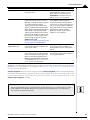
3I4+=$))*&#+)C$+9<.%$+7*@$
The motion processor calculates all trajectory and servo information on a fixed, regular interval. This interval is known
as the cycle time. For each enabled axis of the motion processor, there is a required “time slice” of either 51.2 (MC50000)
or 102.4 (Magellan/ION) microseconds. In addition, for some motion processors there may be added overhead
associated with the trace capture facility, and some internal overhead for multi-axis configurations. The minimum cycle
times for various configurations of the Magellan Motion Processor are provided in the following sections.
!"#$$$$
The following table describes the minimum cycle times for the MC50000 configuration of the Magellan Motion
Processor.
W+:&"D%$4+
SE$/
1 VIONW
1 VMagellan
Single"axisW
1 VMagellan
Multi"axisW
2 VMagellanW
3 VMagellanW
4 VMagellanW
2M
!*&*@3@+
9<.%$+
7*@$
10264 us
5162 µs
9<.%$+7*@$+
PN+7-".$+
9"R)3-$
10264 us
10264 fs
7*@$+
R$-+SE*/
10264 us
5162 fs
10264fs
10264 fs
10264 fs
!"E*@3@+9<.%$+
G-$X3$&.<
9676 kHz
19653 bHz V9676 w/
trace captureW
9676 kHz
15366 fs
20468 fs
256 fs
15366 fs
20468 fs
256 fs
7668 fs
6863 fs
64 fs
6651 bHz
4688 bHz
3691 bHz
Magellan'Motion Processor User’s Guide
9(&)-(%+!(43%$/
3
The minimum cycle time for Magellan/ION does not depend on whether trace has been selected, or any other factors.
The following table summarizes this.
!01e220-3456
The following table describes the minimum cycle time for the Magellan/ION configuration of the Magellan Motion
Processor
!*&*@3@+9<.%$+7*@$
10264 fs
!"E*@3@+9<.%$+G-$X3$&.<
9676 bHz
The cycle rate determines the trajectory update rate for all motor types, as well as the servo loop calculation rate for
the servo products (MC58000, Magellan/ION). It does not necessarily determine the commutation rate, the PWM
rate, or the current loop rate (Magellan/ION only).
An enabled axis receives its cycle time slice whether or not it is in motion, and whether or not all the modules are
enabled. For multi-axis motion processors, if cycle time is critical, it is possible to reclaim that time slice by disabling
an unused axis, and then resetting the loop rate with the instructions SetOperatingMode and SetSampleTime.
For example, using an MC55240, four axes are available. If only three of the axes will be used in a specific application,
then the unused axis may be disabled using the SetOperatingMode command and a new, lower sample time may be
set using the SetSampleTime command. This would improve the cycle frequency from 3.90 kHz to 4.88 kHz.
SetSampleTime may also be used to increase the cycle time to a value greater than the allowed minimum when
required.
SetSampleTime cannot be used to set a sample time lower than the required minimum cycle time for the
current configuration6 Attempting to do so will set the required minimum as the sample time6
3I5+7C$+7*@$+B$#*/)$Magellan processors keep a 32-bit register that holds the current motion processor time, measured as the number of
cycles executed since powerup or reset. This continuously changing value can be read using the command GetTime.
The register has two primary purposes. It can be used as a comparison value for time-based breakpoints (See Section
6.2, Breakpoints for more information). In addition, it can be a useful way of keeping track of actual time elapsed by
manually querying the time.
The Time register increases by a value of 1 for each cycle that the motion processor executes until it reaches its largest
possible value of FFFF FFFFh or 4,294,967,295 dec, at which point it wraps back to zero (0). The point at which the
time wrap will occur depends on the cycle time set for the motion processor. For example, for a 4-axis MC58000 with
the default cycle time of 256 uSec, wrap will occur at 256 uSec * 4,294,967,295 = ~12.7 days. All motion processor
operations will continue normally, although if a time breakpoint has been set, care should be taken to correctly
calculate the comparison time including any potential wrap.
Magellan'Motion Processor User’s Guide
21
3
9(&)-(%+!(43%$/
3IT+2$)Y$-/*(&+9(@@"&4
All Magellan Motion Processors can be queried to provide a unique code that indicates the product type and (if
applicable) version code. To retrieve this information use the GetVersion command. See the Magellan Motion Processor
Programmer’s Command Reference for more information.
22
Magellan'Motion Processor User’s Guide
4I+7-"Z$.)(-<+2$&$-")*(&
:
In This Chapter
!"Trajectories, Profiles, and Parameters
!"Trapezoidal Point-to-Point Profile
!"S-curve Point-to-Point Profile
!"Velocity-Contouring Profile
!"Electronic Gear Profile
!"The SetStopMode Command
!"Disabling and Enabling the Trajectory Generator Module
4I1+7-"Z$.)(-*$/[+,-(>*%$/[+"&4+,"-"@$)$-/
The trajectory generator performs calculations to determine the instantaneous position, velocity, and acceleration of
each axis at any given moment. These values are called the commanded values. During a motion profile, some or all of
these parameters will continuously change. Once the move is complete, these parameters will remain at the same value
until a new move begins.
To query the instantaneous commanded profile values, use the commands GetCommandedPosition,
GetCommandedVelocity, and GetCommandedAcceleration.
The specific profile created by the Magellan Motion Processor depends on several factors, including the presently
selected profile mode, the presently selected profile parameters, and other system conditions such as whether a motion
stop has been requested. Four trajectory profile modes are supported: S-curve point-to-point, trapezoidal point-topoint, velocity contouring, and electronic gearing. The operation of these profile modes will be explained in detail in
subsequent sections. The command used to select the profile mode is SetProfileMode. The command
GetProfileMode retrieves the programmed profile mode.
The profile mode may be programmed independently for each axis. For example, axis #1 may be in trapezoidal mode,
while axis #2 is in S-curve point-to-point mode.
Magellan Motion Processors can switch from one profile to another while an axis is in motion, with only one exception:
when switching to the S-curve point-to-point profile from any other profile, the axis must be at rest.
4I1I1+7-"Z$.)(-<+,"-"@$)$-+B$R-$/$&)")*(&
The Magellan Motion Processor sends and receives trajectory parameters using a fixed-point representation. In other
words, a fixed number of bits is used to represent the integer portion of a real number, and a fixed number of bits is
used to represent the fractional component of a real number. The following table describes the three formats that the
motion processor uses.
Magellan'Motion Processor User’s Guide
23
:
7-"Z$.)(-<+2$&$-")*(&
G(-@")
3260
;(-4+=*\$
32 bits
16616
32 bits
0632
32 bits
B"&#$
d2E147E483E648 to
g2E147E483E647
d32E768 to 32E767
g 65E535/65E536
?$/.-*R)*(&
Unity scaling6 This format uses an integer"only representation of
the number6
0 to
g2E147E483E647/
4E294E967E296
Uses 1/232 scaling6 The motion processor expects a 32"bit number
scaled by a factor of 4E294E967E296 V232W6 For exampleE to specify a
value of 60075E 60075 is multiplied by 4E294E967E296 and the result is
sent to the motion processor as a 32"bit integer V32E212E256 deci"
mal or 00EB8520h6W6
Uses 1/216 scaling6 The motion processor expects a 32"bit number
scaled by a factor of 65E5366 For exampleE to specify a velocity of
2675E 2675 is multiplied by 65E536E and the result is sent to the
motion processor as a 32"bit integer V180E224 dec6 or 0002C000hW6
4I2+7-"R$\(*4"%+,(*&)])(],(*&)+,-(>*%$
The following table summarizes the host-specified profile parameters for the trapezoidal point-to-point profile mode.
,-(>*%$+
,"-"@$)$Position
Starting Velocity
Velocity
Acceleration
G(-@")
3260
16616
16616
16616
;(-4+=*\$
32 bits
32 bits
32 bits
32 bits
B"&#$
d2E147E483E648 to 2E147E483E647 counts6
0 to 32E767 g 65E535/65E536 counts/cycle6
0 to 32E767 g 65E535/65E536 counts/cycle6
Deceleration
16616
32 bits
0 to 32E767 g 65E535/65E536 counts/cycle26
0 to 32E767 g 65E535/65E536 counts/cycle26
The host instructions SetPosition, SetStartVelocity, SetVelocity, SetAcceleration, and SetDeceleration load
these values. The commands GetPosition, GetStartVelocity, GetVelocity, GetAcceleration, and
GetDeceleration retrieve the programmed values.
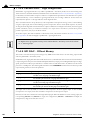
For this profile, the host specifies an initial acceleration and deceleration, a velocity, and a destination position. The
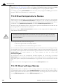
profile gets its name from the resulting curve (see Figure 4-1). The axis accelerates linearly (at the programmed
acceleration value), until it reaches the programmed velocity. It continues in motion at that velocity, then decelerates
linearly (using the deceleration value) until it stops at the specified position.
#igure :*1+
Simple
trape=oidal
point*to*point
profiles
A Z acceleration
D Z deceleration
Y Z velocity
Yelocity
Y
A
D
Time
CD
CA
CY
24
Magellan'Motion Processor User’s Guide
7-"Z$.)(-<+2$&$-")*(&
:
Figure 4-1 illustrates a trapezoidal profile with the starting velocity set at the default value of zero (0). When wholestepping a step motor, it is sometimes desirable to define a non-zero starting velocity from which the motor will
instantaneously begin motion. This is to avoid passing through the resonant frequency of a step motor. In the
deceleration phase of the profile, rather than continuously decelerate to a velocity of zero (0), the velocity will
transition from the start velocity to zero (0) velocity with no deceleration phase in between. Figure 4-2 shows a typical
trapezoidal profile with non-zero starting velocity.
#igure :*2+
?rape=oidal
profile @ith
non*=ero
starting
velocity
A Z acceleration
D Z deceleration
Y Z velocity
Yelocity
Y
D
A
Atarting
Yelocity
Time
Atarting
Yelocity
CA
CD
CY
Note that a programmable starting velocity is supported in Trapezoidal and Velocity Contouring profile modes only.
It is not supported in Electronic Gear or S-curve profile modes.
If deceleration must begin before the axis reaches the programmed velocity, the profile will have no constant velocity
portion, and the trapezoid becomes a triangle, as shown in Figure 4-3.
#igure :*3+
Simple
trape=oidal
point*to*point
profile
Yelocity
A Z acceleration
D Z deceleration
A
D
Time
The slopes of the acceleration and deceleration segments may be symmetric (if acceleration is equal to deceleration),
or asymmetric (if acceleration is not equal to deceleration).
The acceleration parameter is always used at the start of the move. Thereafter, the acceleration value will be used when
the absolute value of velocity is increasing, and deceleration will be used when the absolute value of velocity is
Magellan'Motion Processor User’s Guide
25
:
7-"Z$.)(-<+2$&$-")*(&
decreasing. If no motion parameters are changed during the motion, then the acceleration value will be used until the
maximum velocity is reached. The deceleration value will be used when ramping down to zero (0).
A Z acceleration
D Z deceleration
YD, Y) Z velocity
change velocity
YD
Yelocity
#igure :*:+
Complex
trape=oidal
point*to*point
profile,
sho@ing
parameter
changes
A
D
Y)
change target position
D
Time
CA
CD
reverse direction
CY)
It is acceptable to change any of the profile parameters while the axis is moving in this profile mode. The profile
generator will always attempt to remain within the legal bounds of motion specified by the parameters. If, during the
motion, the destination position is changed in such a way that an overshoot is unavoidable, the profile generator will
decelerate until stopped, then reverse direction to move to the specified position. This is illustrated in Figure 4-4
If a deceleration value of zero (0) is programmed (or no value is programmed, leaving the motion processor’s default
value of zero[0]), then the value specified for acceleration (SetAcceleration) will automatically be used to set the
magnitude of deceleration.
4I3+=].3-A$+,(*&)])(],(*&)+,-(>*%$
The following table summarizes the host-specified profile parameters for the S-curve point-to-point profile mode.
,-(>*%$+
,"-"@$)$Position
Velocity
Acceleration
G(-@")
3260
16616
16616
;(-4+=*\$
32 bits
32 bits
32 bits
B"&#$
d2E147E483E648 to 2E147E483E647 counts6
0 to 32E767 g 65E535/65E536 counts/cycle6
Deceleration
16616
32 bits
0 to 32E767 g 65E535/65E536 counts/cycle26
Jerk
0632
32 bits
0 to 2E147E483E647/4E294E967E296 counts/cycle36
0 to 32E767 g 65E535/65E536 counts/cycle26
The host instructions SetPosition, SetVelocity, SetAcceleration, SetDeceleration, and SetJerk load these
respective values. The commands GetPosition, GetVelocity, GetAcceleration, GetDeceleration, and GetJerk
retrieve the programmed values.
In S"curve profile modeE the same value must be used for both acceleration and deceleration6 Asymmetric profiles
are not allowed6
2T
Magellan'Motion Processor User’s Guide
7-"Z$.)(-<+2$&$-")*(&
:
The S-curve point-to-point profile adds a limit to the rate of change of acceleration to the basic trapezoidal curve. A
new parameter (jerk) is added which specifies the maximum change in acceleration in a single cycle.
In this profile mode, the acceleration gradually increases from 0 to the programmed acceleration value, then the
acceleration decreases at the same rate until it reaches 0 again at the programmed velocity. The same sequence in
reverse brings the axis to a stop at the programmed destination position.
Aegments
I
II
III
Yelocity
C,
IY
Y
Y
YI
#igure :*F+
?ypical S*curve
point*to*point
profile
YII
A 0,,$1$%0"+/n
D )$,$1$%0"+/n
Y&&*$1/,+"2
,&&&3$%4
C,
A
D
,
,
Time
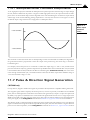
Figure 4-5 shows a typical S-curve profile. In Segment I, the S-curve profile drives the axis at the specified jerk (J) until
the maximum acceleration (A) is reached. The axis continues to accelerate linearly (jerk = 0) through Segment II. The
profile then applies the negative value of the jerk to reduce acceleration to 0 during Segment III. The axis is now at
maximum velocity (V), at which it continues through Segment IV. The profile will then decelerate in a manner similar
to the acceleration stage, using the jerk value first to reach the maximum deceleration (D) and then to bring the axis
to a halt at the destination.
An S-curve profile might not contain all of the segments shown in Figure 4-5. For example, if the maximum
acceleration cannot be reached before the “halfway” point to or from the velocity, the profile would not contain a
Segment II or a Segment VI. Such a profile is shown in Figure 4-6.
Aegments
I
III
IY
Y
YII
#igure :*6+
S*curve that
does not reach
maximum
acceleration
Yelocity
Y
C,
C,
,
Y&&*$1/,+"2
,&&&3$%4
,
Time
Similarly, if the position is specified such that velocity is not reached, there will be no Segment IV, as shown in Figure
4-7. There may also be no Segment II or Segment VI depending on where the profile is truncated.
Magellan'Motion Processor User’s Guide
27
:
7-"Z$.)(-<+2$&$-")*(&
#igure :*H+
S*curve @ith
no maximum*
velocity
segment
Aegments
I
III
Y
Yelocity
C,
YII
C,
,&&&3$%4
,
,
Time
Unlike the trapezoidal profile modeE the S"curve profile mode does not support changes to any of the profile pa"
rameters while the axis is in motion6
An axis may not be switched into S-curve profile mode while the axis is in motion. It is legal to switch from S-curve
mode to any other profile mode while in motion.
4I4+Y$%(.*)<]9(&)(3-*&#+,-(>*%$
The following table summarizes the host-specified profile parameters for the velocity-contouring profile mode.
,-(>*%$+
,"-"@$)$Start Velocity
Velocity
G(-@")
16616
16616
;(-4+=*\$
32 bits
32 bits
B"&#$
0 to 32E767 g 65E535/65E536 counts/cycle6
d32E768 to 32E767 g 65E535/65E536 counts/
cycle6
Acceleration
16616
32 bits
0 to 32E767 g 65E535/65E536 counts/cycle26
Deceleration
16616
32 bits
0 to 32E767 g 65E535/65E536 counts/cycle26
The host instructions SetStartVelocity, SetVelocity, SetAcceleration, and SetDeceleration load these respective
values. The commands GetStartVelocity, GetVelocity, GetAcceleration, and GetDeceleration retrieve the
programmed values.
Unlike the trapezoidal and S-curve profile modes where the destination position determines the direction of initial
travel, in the velocity-contouring profile mode, the sign of the velocity parameter determines the initial direction of
motion. Therefore, the velocity value sent to the motion processor can have positive values (for positive direction
motion), or negative values (for negative direction motion).
2L
Magellan'Motion Processor User’s Guide
7-"Z$.)(-<+2$&$-")*(&
:
In this profile, no destination position is specified. The motion is controlled entirely by changing the acceleration,
velocity, and deceleration parameters while the profile is being executed.
In velocity"contouring profile modeE axis motion is not bounded by a destination6 It is the hostis responsibility to
provide accelerationE decelerationE and velocity values that result in safe motion within acceptable position limits6
The trajectory is executed by continuously accelerating the axis at the specified rate until the velocity is reached. The
axis starts decelerating when a new velocity is specified with a smaller value (in magnitude) than the present velocity,
or a sign that is opposite to the present direction of travel. Figure 4-8 illustrates a more complicated profile, in which
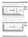
both the velocity and the direction of motion change twice.
As was the case for the Trapezoidal Profile mode, in addition to a maximum velocity, a starting velocity value can be
specified which will cause the profile to instantly begin motion at that velocity, and instantly decelerate to zero (0) from
that starting velocity.
increase velocity
decrease velocity
decrease velocity
A1, A2 = acceleration
D1 = deceleration
V1, V2, V3, V4, V5 = velocity
+
#igure :*8+
Velocity*
contouring
profile
Velocity
V2
D1
A1
V5
V3
A2
V1
D1
A1
Time
_
–D1
–A2
V4
change velocity,
acceleration
4I5+:%$.)-(&*.+2$"-+,-(>*%$
The following table summarizes the host-specified profile parameters for the electronic gear profile mode.
,-(>*%$+
,"-"@$)$Gear Ratio
Master Axis \
Master Source
G(-@")
16616
"
"
;(-4+=*\$
32 bits
2 bits
1 bit
B"&#$
d32E768 to 32E767 g 65E535/65E536 counts/cycle6
0d3j
2 valuesk encoder or commanded Vsee below for more
information6W
The host instructions SetGearRatio and SetGearMaster load these respective values. The commands
GetGearRatio and GetGearMaster retrieve the programmed values.
In this profile, the host specifies three parameters. The first is the master axis number. This is defined as the axis that
will be the source of position information used to drive the slave axis, which is the axis in gear mode. The second is
Magellan'Motion Processor User’s Guide
2V
:
7-"Z$.)(-<+2$&$-")*(&
the gear source, which is either actual (the encoder position of the master axis), or commanded (the commanded
position of the master axis). The third is the gear ratio, which specifies the direction and ratio of master gear counts
to slave counts.
Normally, the slave axis is set to an axis different than the master axis. One allowed exception is when step motors are
being used. In this case, the master axis may be set to the same axis as the slave, as long as the gear source is set to
encoder. For servo motors, the master axis must be a different axis than the slave axis.
Note that for Magellan/ION, the “auxiliary axis” is treated as the second axis.
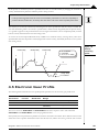
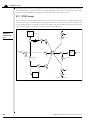
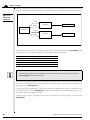
Figure 4-9 shows the arrangement of encoders and motor drives in a typical electronic gearing application.
#igure :*K+
Llectronic gear
profile
Motor
Alave encoder
Amplifier
Magellan Motion Processor
/5"+/n01
Master encoder
Amplifier
Motor
A positive gear ratio value means that during an increase in either the master axis actual or commanded position, the
slave commanded position will also increase. A negative gear ratio value has the opposite effect: increasing master
position will result in decreasing slave axis commanded position.
For example, assume the slave axis is axis #1 and the master axis is set to axis #4. Also, assume the source will be
actual with a gear ratio of –1/2. Then for each positive encoder count of axis 4, axis 1 commanded position will
decrease in value by 1/2 count, and for each negative encoder count of axis 4, axis 1 commanded position will increase
in value by 1/2 count.
The electronic gear profile requires two axes to be enabled. The single-axis motion processors do not support
electronic gearing.
If the master axis source is set to actual, then this axis need not have a physical motor attached to it. Frequently, it is used
only for its encoder input, for example, from a directly driven (open-loop) motor, or a manual control. It is possible to
drive a motor on the master axis by enabling the axis and applying a profile mode other than electronic gear to the axis.
The effect of this arrangement is that both master and slave can be driven by the same profile, even though the slave can
drive at a different ratio and in a different direction if desired. The master axis will operate the same, whether or not it
happens to be the master for some other geared axis. The “optional” components shown in Figure 4-9 illustrate this
arrangement. Such a configuration can be used to perform useful functions such as linear interpolation of two axes.
3M
Magellan'Motion Processor User’s Guide
7-"Z$.)(-<+2$&$-")*(&
:
The gear ratio parameter may be changed while the axis is in motionE but care should be taken to select ratios so
that safe motion is maintained6
Note that unlike the trapezoidal, S-curve, and velocity contouring profile modes, electronic gearing profile mode does
not have an explicit sense of whether motion is “completed” or not. Therefore, the “motion complete” bit of the Event
Status register, as well as the “in-motion” bit of the Activity Status register, do not function when in this profile mode.
For ION 3000 usersE Electronic gear can also be used with a pulse & direction input signal for the auxiliary
encoder axis6 In this modeE all the standard electronic gear commands are usedE with one master axis input lpulsea
being equivelent to one master axis input encoder lticka6 To operate the ION in this mode the master axis number
is set to \2 Vauxiliary axisW and the encoder source is set to pulse & direction6 See Chapter 10, Encoder Interfacing
for more information on the SetEncoderSource command6
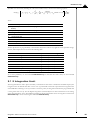
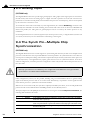
4IT+7C$+=$)=)(R!(4$+9(@@"&4
Normally, each of the trajectory profile modes will execute the specified trajectory, within the specified parameter limits, until
the profile conditions are satisfied. For example, for the point-to-point profile modes this means that the profile will move
the axis until the final destination position has been reached, at which point the axis will have a velocity of zero (0).
In some cases, it may be necessary to halt the trajectory manually, either for safety reasons, or simply to achieve a
specific profile. This may be accomplished using one of two methods: Abrupt Stop or Smooth Stop.
To perform a stop, the command SetStopMode is used. To retrieve the current stop mode, the command GetStopMode
is used. Using the SetStopMode command to set the mode to Abrupt Stop instantaneously stops the profile by setting the
target velocity of the designated axis to zero (0). This is, in effect, an emergency stop with instantaneous deceleration.
Setting the stop mode to Smooth Stop brings the designated axis to a controlled stop, using the current deceleration
parameter to reduce the velocity to zero (0).
In either mode, the target velocity is set to zero (0) after the SetStopMode command is executed. Before any other
motion can take place, the velocity must then be reset using the SetVelocity command.
F<+38($G(58 must be used with care6 Sudden deceleration from a high velocity can damage equipment or cause
injury6
Abrupt Stop functions in all profiles. Smooth Stop functions in all profiles except electronic gearing.
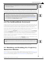
4I7+?*/"D%*&#+"&4+:&"D%*&#+)C$+7-"Z$.)(-<+
2$&$-")(-+!(43%$
There are a number of reasons why it might be desirable to disable the trajectory generator module. See Section 3.1, Control
Flow Overview for more information on the functions of the Trajectory Generator. In addition, there are event-related actions
that may result in this module being disabled. See Section 8.1, SetEventAction Processing for more information.
Magellan'Motion Processor User’s Guide
31
:
7-"Z$.)(-<+2$&$-")*(&
If the trajectory generator module is disabled, the current commanded position will remain at its present value. All
profile and other commands will be ignored. In addition, if the position loop is enabled, at the time the trajectory
generator module is disabled, the position error will be set to 0 (equivalent to ClearPositionError command).
A previously disabled trajectory generator module may be re-enabled in a number of ways. If the module was disabled
using the SetOperatingMode command, then another SetOperatingMode command may be issued. If the
trajectory generator module was disabled as part of an automatic event-related action (see Section 8.1, SetEventAction
Processing for more information) then the command RestoreOperatingMode is used.
32
Magellan'Motion Processor User’s Guide
5I+,(/*)*(&+F((R
F
In This Chapter
!"Overview
!"Dual Encoder Support
!"Biquad Output Filters
!"Output Limit
!"Motor Bias
!"Disabling and Enabling the Position Loop Module
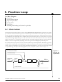
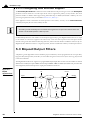
5I1+6A$-A*$P
For motion processors that provide servo motor support (MC58000 Series, Magellan/ION), a position loop is used as
part of the basic method of determining the motor command output. The function of the position loop is to match as
closely as possible the commanded position, which comes from the trajectory generator, and the actual motor position.
To accomplish this, the commanded value is combined with the actual encoder position to create position error, which
is then passed through a digital PID-type servo filter. The scaled result of the filter calculation is the motor command,
which is then passed to a “downstream” module, either the commutation/phasing module, the current loop/FOC
module, or the motor output module, depending on the motor type chosen and Magellan product being used.
The overall position loop is split into two major sections, the PID loop, and the biquad filters. The PID loop generates
an initial motor command, while the dual biquad filters can be used to perform various frequency-domain filtering such
as notch, lowpass, and bandpass. Once the output of the PID and biquad filters is generated, it can be further limited
to a prescribed range, thereby accommodating amplifiers, motors, or physical systems, as shown in Figure 5-1.
#igure F*1+
PID loop and
4iPuad filters
Commanded Acceleration
Commanded Yelocity
Commanded
Position
\
Position
Wrror
C
PID
Uilter
\\
\
>i[uad
D
>i[uad
)
\
Motor
Command
\
Motor
Limit
Position Wncoder
Magellan'Motion Processor User’s Guide
Motor
>ias
33
F
,(/*)*(&+F((R
To perform position control, all servo applications require that safe and stable PID loop parameters be specified. Use
of the dual biquad filters, on the other hand, is optional and will depend on the nature and complexity of the control
problem. The more demanding the application, the more likely that the biquads will be useful.
5I1I1+,8?+F((R
The servo filter used with the Magellan Motion Processors is a proportional-integral-derivative (PID) algorithm, with
velocity and acceleration feed-forward terms and an output scale factor. An integration limit provides an upper bound
for the accumulated error. An optional bias value may be added to the filter calculation to produce the final motor
output command. Figure 5-2 provides a control flow overview of the PID loop:
commanded velocity
#igure F*2+
Position loop
flo@
]
CD
E
integration
limit
commanded
position
B
F
G
`i
)^E
F
encoder
feedback
C
G
+
F
` vff
E
bi[uad
filters
F
`p
G
derivative
time
output
E^,^_E
` out
B
F
`d
]
CD
F
` aff
F
1
commanded acceleration
34
Magellan'Motion Processor User’s Guide
,(/*)*(&+F((R
F
The PID+Vff+Aff formula, including the scale factor and bias terms, is shown in the following equation:
n
Output n % K p E n & K d ! E k # E k # " " &
CmdVel
K i*
# Ej $ ********
& K vff '% *********************(& & K aff ! CmdAccel $ , "
+
'()
j%$
K out
$ ******************
)() (-)
where
k
En
Ek
m n d modulus Vn/derivative timeW
m position loop error at the derivative sampling interval VCommanded Position d Actual
PositionW
m position loop error at the derivative sampling interval
bi
m Integral Gain
bd
m Derivative Gain
bp
m Proportional Gain
baff m Acceleration feed"forward
bvff m Velocity feed"forward
bout m scale factor for the output command
All filter parameters are programmable, so that the filter may be fine-tuned to any application. The parameter ranges,
formats, and interpretations are shown in the following table.
7$-@
Ilimit
bi
5"@$
Integration Limit
Integral Gain
B$R-$/$&)")*(&+^+B"&#$
unsigned 32 bits V0 to 2E147E483E647W
unsigned 16 bits V0 to 32E767W
bd
Derivative Gain
unsigned 16 bits V0 to 32E767W
bp
Proportional Gain
unsigned 16 bits V0 to 32E767W
baff
Acceleration feed"forward
unsigned 16 bits V0 to 32E767W
bvff
Velocity feed"forward
unsigned 16 bits V0 to 32E767W
bout
Output scale factor
unsigned 16 bits V0 to 32E767W
DerivativeTime
Derivative Sampling Time
unsigned 16 bits V1 to 32E767W
To set servo parameters, use the command SetPositionLoop. To read back these same values, use the command
GetPositionLoop.
5I1I2+8&)$#-")*(&+F*@*)
The integration limit is used to place a boundary on the absolute value that is contributed to the PID output by the
integration term. Its default value after a reset is zero (0), which will result in the output from the integration term
of the PID filter evaluating to zero (0). In order to use the Ki value, the integration limit must be programmed with
a value greater than zero (0). See the Magellan Programmer’s Command Reference for more information on the scaling
of the integration limit. As for other PID loop parameters, the integration limit can be set using the host instruction
SetPositionLoop. It can be read using the command GetPositionLoop.
Magellan'Motion Processor User’s Guide
35
F
,(/*)*(&+F((R
5I1I3+63)R3)+/."%*&#
The Kout parameter can be used to scale down the output of the PID filter by multiplying the filter result by Kout/
65,536. It has the effect of increasing the usable range of Kp. The Kout value is set using the host instruction
SetPositionLoop. It is read by using the command GetPositionLoop.
Unlike the default value of most PID loop parameters, which is zero (0), Kout has a power-up default value of 65,535, or 100%.
5I1I4+?$-*A")*A$+="@R%*&#+7*@$
Normally, the derivative term of the PID loop is recalculated at every servo cycle. Under some circumstances,
however, it may be desirable to reduce the derivative sampling rate to a rate lower than this, to improve system stability,
or simplify tuning. This can be accomplished using the command SetPositionLoop, and the value set can be read back
using the command GetPositionLoop.
The specified value is the desired number of servo cycles per motion processor sample time. For example, if the
motion processor’s sample time (set using SetSampleTime command) has been set to 200 uSec (giving an effective
sampling time of 204.8 uSec), a value of 1 programmed in the DerivativeTime register will result in a derivative
sample time of 204.8 uSec, while a value of 10 will result in a sample time of 2.048 mSec, or once every 10 servo cycles.
Changing the derivative sample time has no effect on the overall motion processor sample time set using the command
SetSampleTime.
The default value for the derivative time is 1, meaning that by default the derivative term is calculated at each servo cycle.
5I2+?3"%+:&.(4$-+=3RR(-)
The multi-axis MC58000 motion processors (MC58420, MC58320, MC58220) and the Magellan/ION support a dual
encoder PID configuration, which may be useful for applications where the position of the load is critical, but cannot be
deterministically related to the motor position because of backlash or other forms of mechanical compliance. In this
configuration, the encoder input for a second axis (other than the one being controlled) is incorporated as the derivative term
in the servo loop as shown in Figure 5-3. For the Magellan/ION, this second axis is known as the auxiliary encoder input.
For axes driving brushless DC motors in dual encoder mode, the auxiliary axis encoder is used for sinusoidal commutation.
Figure 5-3 provides an overall connection scheme for axes used in the dual loop configuration.
#igure F*3+
Magellan
dual*loop flo@
C o m m a n d e d A c ce le ra tio n
C o m m a n d e d Y e lo city
C om m anded
P o sitio n
\
C
PI
\\
\
C
> i[ u a d
D
> i[ u a d
)
\
M o to r
C om m and
\
M o to r
L im it
D
M o to r
> ia s
M o to r W n c o d e r
L o a d W n co d e r
3T
Magellan'Motion Processor User’s Guide
,(/*)*(&+F((R
F
5I2I1+?3"%+:&.(4$-+,8?+F((R+S%#(-*)C@
The structure of the servo filter used by the motion processor in dual-encoder mode is slightly different from that
used in single-encoder mode. The dual-encoder algorithm that follows is illustrated in Figure 5-4:
n
Output n % K p E" n # K d ! P n # P n # " " &
K
i
* & K vff ' CmdVel
*********************( & K aff ! CmdAccel $ , "
# E"j $ ********
%
'()
+ &
j%$
K out
$ ******************
)() (-)
where
E1n
m the accumulated error terms from the main encoder
Pn
m position of the auxiliary encoder
bi
m Integral Gain
bd
m Derivative Gain
bp
m Proportional Gain
baff
m Acceleration feed"forward
bvff
m Velocity feed"forward
bout
m scale factor for the output command
#igure F*:+
Magellan dual*
loop digital
filter
commanded velocity
] CD
E
integration
limit
commanded
position
F
G
`i
)^E
B
F
encoder
feedback
`p
C
E
G
+
F
`vff
bi[uad
filters
F
G
output
E^,^_E
`out
auxiliary
encoder
B
F
`d
] CD
F
`aff
F
1
commanded acceleration
Magellan'Motion Processor User’s Guide
37
F
,(/*)*(&+F((R
5I2I2+9(&>*#3-*&#+?3"%+:&.(4$-+=3RR(-)
The SetAuxiliaryEncoderSource command is used to enable dual encoder processing for an axis. The AuxiliaryAxis
parameter controls which axis’ encoder input will be used to augment the primary (Load) encoder. The mode
parameter enables or disables dual loop processing. When dual loop is disabled (the default condition), the servo
processing loop functions exactly as described in Section 5.1.1, PID Loop .”
If the application needs to determine the actual position of the auxiliary encoder, use the GetActualPosition
command, and specify the axis of the auxiliary encoder.
The auxiliary encoder should always have a resolution which is greater than or equal to the resolution of the main
encoder to avoid unstable operation in dual loop mode6
For MC50000 products the total number of encoder inputs supported by a given Magellan Motion Processor is equal
to the number of control axes supported. In other words, a four-axis motion processor has four input encoder
channels. Using an encoder channel for dual-loop, therefore, reduces the total number of available control axes by one.
Magellan/ION is different in that it is a single axis product, but has an additional “auxiliary” encoder input channel.
5I3+_*X3"4+63)R3)+G*%)$-/
A biquad is a generic digital filter structure. With the proper coefficients, it can be programmed to be a low-pass filter,
high-pass filter, band-pass filter, notch filter, or custom filter. Programs such as Octave (www.octave.org) may be used
to find the coefficients.
The Magellan Motion Processor supports two programmable biquad output filters for each axis. These filters are chained.
When both are enabled, the output of Filter1 feeds the input of Filter2. If Filter1 is disabled (the default state), the entire filter
chain is bypassed, and the motion processor output passes unfiltered to the motor.
#igure F*F+
QiPuad
algorithm flo@
Input
X
]
]
3L
`Acalar
>0
CD
CD
\
X
\\ \ \
>D
AD
X
X
>)
A)
X
X
]
CD
]
CD
Output
Magellan'Motion Processor User’s Guide
,(/*)*(&+F((R
F
The output of the filter at time n is determined with the following equation:
Yn % K $ ! B$ $ Xn & B" $ Xn # " & B' $ Xn # ' & A" $ Yn # " $ A' $ Yn # ' "
where:
pn
m output of the filter at time n
qn
m input to the filter at time n
b
B0
m positive scaling value used to avoid rounding errors
m programmable biquad coefficient
B1
m programmable biquad coefficient
B2
m programmable biquad coefficient
A1
m programmable biquad coefficient
A2
m programmable biquad coefficient
The following table shows biquad filter coefficients that are set using the command SetPositionLoop. They can be
read back using the command GetPositionLoop. The following table also summarizes the representation and range
for the settable biquad parameters.
7$-@
b
A1
5"@$
biquad scalar
coefficient A1
B$R-$/$&)")*(&+^+B"&#$
unsigned 16 bits V0 to 32E767W
signed 16 bits Vd32E768 to 32E767W
A2
coefficient A2
signed 16 bits Vd32E768 to 32E767W
B0
coefficient B0
signed 16 bits Vd32E768 to 32E767W
B1
coefficient B1
signed 16 bits Vd32E768 to 32E767W
B2
coefficient B2
signed 16 bits Vd32E768 to 32E767W
5I3I1+?$)$-@*&*&#+_*X3"4+9($>>*.*$&)/
Typically, coefficients used in biquad filter equations are small floating point numbers. To avoid rounding errors when
storing these numbers as 16-bit values, the K coefficient is scaled by 227 to allow the other coefficients to be entered as
integers.
For example, in Octave, the coefficients for a second-order butterworth filter can be found as:
nbEao m butterV2E061W
This results in the coefficients:
b0 m 06020083
b1 m 06040167
b2 m 06020083
a1 m d1656102
a2 m 0664135
If the motion processor’s filter equation (shown at the top of this page) is compared to the filter equation used by
Octave (type help filter in Octave), there is a slight difference in that the ax components are subtracted in Octave, as
opposed to being added in the motion processor. The result is that the a1 and a2 coefficients from Octave (or Matlab)
need to be multiplied by PD before being sent to the motion processor. This results in:
b0 m 06020083
b1 m 06040167
b2 m 06020083
a1 m 1656102
a2 m d0664135
Once the output scaling factor b is determined, these values will be scaled and set as the output filter coefficients.
Magellan'Motion Processor User’s Guide
3V
F
,(/*)*(&+F((R
5I3I2+?$)$-@*&*&#+)C$+_*X3"4+=."%*&#+G".)(To obtain maximum output precision, the programmable scaling value b should be set to a value which will scale the
largest absolute value of the set of coefficients (a1 in this case) closest to 32,767 (the largest positive value for a 16-bit
signed integer). Note that in this step, if the coefficients are not chosen correctly there is the potential to create an
overflow result. Using the coefficient values on the previous page (and accounting for the 227 internal scaling factor),
b is determined using this equation.
a1 m b j 32767 j 2d27
which can be easily resolved:
restated as:
b = Va1 j 227W / 32767
substituting:
evaluates to:
b m V1656102 j 227W / 32767
b m 6394
5I3I3+=."%*&#+_*X3"4+9($>>*.*$&)/
Once the optimal b scaling factor has been determined, the integer equivalents of the biquad coefficients must be
calculated. These integer values (named B0E B1E B2E A1E and A2) are calculated as shown in the following example.
b0 m B0 j b j 2d27
restated as:
B0 m Vb0j 227W / b
substituting:
evaluates to:
B0 m V06020083 j 227W / 6394
B0 m 422
Using this formula (q m Vx j 227W / b) for each of the coefficients yields:
B0 m 422
B1 m 843
B2 m 422
A1 m 32767
A2 m d13463
b m 6394
5I4+63)R3)+F*@*)
The motor output limit prevents the filter output from exceeding a boundary magnitude in either direction. If the filter
produces a value greater than the limit, the motor command takes the limiting value. The motor limit value is set using
the host instruction SetMotorLimit. It is read by using the command GetMotorLimit. The value specified is a 16bit unsigned number with a range of 0 to 32,767. The specified value is the maximum magnitude that will be output
to the motor. For example, if the motor limit is set to 30,000 (or 91.6% output), then motor values greater than 30,000
will be output as 30,000, and motor values less than –30,000 will be output as –30,000.
The motor limit applies only when the position loop is enabled. In the case that the position loop is disabled, the
output limit does not affect either the value passed on from the trajectory generator, or the value specified from the
Motor Command register.
The default value of the motor command limit is 32,767, which corresponds to 100% output.
4M
Magellan'Motion Processor User’s Guide
,(/*)*(&+F((R
F
5I5+!()(-+_*"/
When an axis is subject to a net external force in one direction (such as a vertical axis pulled downward by gravity),
the servo filter can compensate for it by adding a constant DC bias to the filter output. As for the regular PID values,
the bias value is set using the host instruction SetMotorBias. It can be read using the command GetMotorBias.
The motor bias is applied at all times that the position loop is enabled. If the position loop is disabled but the trajectory
generator is enabled, the motor bias is also applied at all times.
If the position loop is disabled and the trajectory generator is also disabled, then the motor bias is applied only after a
transition to this state, and any subsequent setting of the Motor Command register will be applied without motor bias.
See Section 5.6, Disabling and Enabling the Position Loop Module for more information on setting the Motor Command
register. For example, if a motor bias value of +1,000 (= ~+3%) has been set, at the time a SetOperatingMode
command is given to disable trajectory generator and position loop, or at the time a safety-related response such as
motion error occurs and these modules are automatically disabled, the output motor command will be +1,000. If, in
the process of recovering from this condition, a user sets the motor command to +2,000, this value, unaffected by the
motor bias, will be output.
The default value of motor bias is zero (0).
If the specified bias value does not properly compensate for the external forceE the axis may move suddenly in one
direction or another after a SetOperatingMode command6 It is the responsibility of the user to select a motor
bias value which will maintain safe motion6
5IT+?*/"D%*&#+"&4+:&"D%*&#+)C$+,(/*)*(&+
F((R+!(43%$
There are a number of reasons why it might be desirable to disable the position loop module. See Section 3.1, Control
Flow Overview for more information. In addition, there are event-related actions that may result in this module being
disabled. See Section 8.1, SetEventAction Processing for more information.
If the position loop module is disabled, the overall control flow of the motion processor module will be altered in one
of two ways, depending on whether the trajectory generator is enabled or disabled when the position loop module is
disabled.
Trajectory generator disabled — If the trajectory generator module is disabled when the position loop is disabled,
the output of the position loop module will be a 16-bit word derived from a programmable motor command register,
set using SetMotorCommand, and read back using GetMotorCommand.
Trajectory generator enabled — If the trajectory generator module is enabled when the position loop is disabled,
then the position loop module is bypassed, and the output value of the trajectory generator becomes the motor
command value. Note that only the low word of the 32-bit commanded position is used. This is because the output
of the trajectory generator is a 32-bit commanded position, while the output of the position loop, and therefore the
input to subsequent modules, is a 16-bit motor command. Effectively this means that when used in this mode, the
range of the trajectory generator is limited to 16 bits (–32,768 to +32,767).
Regardless of whether the position loop module is enabled or disabled, the actual effective motor command value may
be queried using the command GetActiveMotorCommand. This value will indicate the motor command being sent
to “downstream” processing modules such as commutation, current control (Magellan/ION only), or motor output.
Magellan'Motion Processor User’s Guide
41
F
,(/*)*(&+F((R
#igure F*6+
Motor control
paths,
traRectory
ena4ledS
disa4led
Motor command
register
Trajectory c
position loop
disabled
To commutation,
current loop or
motor output
module
Trajectory or
position loop
enabled
Trajectory generator
Position Loop
Actual position Hfrom encoderL
A previously disabled position loop module may be re-enabled in a number of ways. If the module was disabled using
the SetOperatingMode command, then another SetOperatingMode command may be issued. If the position loop
module was disabled as part of an automatic event-related action (see Section 8.1, SetEventAction Processing for more
information) then the command RestoreOperatingMode is used.
Regardless of how the module is re-enabled, at the time that the re-enable operation is requested, certain special
processing occurs to avoid unexpected axis movement. In particular, all position loop state variables are set to zero(0).
5ITI1+B$"4*&#+,(/*)*(&+F((R+Y"%3$/
As indicated in this chapter and others, there are a number of commands which can be used to read various position
loop-related values. These include GetCommandedPosition to read the input command of the position loop,
GetActualPosition to read the actual encoder position, GetPositionError to read the difference between these two
quantities, and GetActiveMotorCommand to read the output of the position loop module. In addition to being
readable through these commands, these variables can also be selected for tracing. See Section 8.8, Trace Capture for
more information on Magellan’s capture trace facility.
Beyond these registers, to further facilitate tuning, there are a number of internal position loop values that can be read
back as well as traced. To read back these values the command GetPositionLoopValue is used.
The variables within the position loop that can be read and traced are summarized in the following table.
Y"-*"D%$+5"@$
Integrator Sum
Integral Contribution
Derivative
BiTuad1 Input
BiTuad2 Input
42
G3&.)*(&
This register holds the sum of the integrator for the position PID loop6
This register holds the overall contribution of the integrator to the position
PID loop6
This register holds the position error derivative value6 That isE the difference
between the present position error and the previous one6
This register holds the input value to biquad filter 16
This register holds the input value to biquad filter 26
Magellan'Motion Processor User’s Guide
TI+,"-"@$)$-+0R4")$+"&4+
_-$"`R(*&)/
6
In This Chapter
!"Parameter Buffering
!"Breakpoints
TI1+,"-"@$)$-+_3>>$-*&#
Various parameters must be specified to the motion processor for an axis to be correctly controlled. Some situations
may require that a set of parameters take effect at the exact same time to facilitate precise synchronized motion. To
support this, all profile parameters, most position loop parameters, and most current loop parameters, are loaded into
the motion processor using a buffered scheme. These buffered commands are stored in an area of the motion processor
that does not affect the actual motion processor behavior until an Update event occurs. An Update results in buffered
registers being copied to the active registers, thereby causing the motion processor to act on the new parameters.
There are three separate types of buffered registers, each of which may be independently updated and made active. They
are the profile parameters, the position loop parameters, and the current loop parameters. The command
SetUpdateMask controls which of these three types will be copied upon receipt of an Update command. The
command GetUpdateMask is used to read back the specified mask value. Separately updateable parameters are useful
because they allow (for example) the profile parameters to be modified on-the-fly without affecting the servo
parameters, or the current loop parameters to be changed without altering the position loop parameters. Many
applications will not need this complexity, however, and it is not uncommon for the mask to be set just once, so that all
three buffered register types are always updated.
The following command sequence illustrates the loading and updating of a set of parameters. In this case, a new profile
mode, position, velocity, and acceleration (all of which are buffered commands) are loaded, followed by an update
command to make them active.
SetProfileMode Axis1E trapezoidal
SetPosition Axis1E 12345
SetVelocity Axis1E 223344
SetAcceleration Axis1E 1000
SetUpdateMask Axis1E Profile
Update
// set profile mode to trapezoidal for axis 1
// load a destination position for axis 1
// load a velocity for axis 1
// load an acceleration for axis 1
// specify that an update of profile parameters only
// is to occur
// Double buffered registers are copied into
// the active registersE thereby initiating the move
In this sequence, the trajectory profile mode will actually be changed to trapezoidal and the specified parameters loaded
into the trajectory generator only when the Update occurs. At that point the trajectory generator will begin the
programmed motion.
The value set using the SetUpdateMask command is only altered by a subsequent SetUpdateMask command. That
is, its value is not affected by the Update command itself or by any other commands.
The default value of the update mask for MC50000 motion processors is to update profile parameters and servo
parameters. The default value for Magellan/ION is to update profile parameters, servo parameters, and current loop
parameters.
Magellan'Motion Processor User’s Guide
43
6
,"-"@$)$-+0R4")$+"&4+_-$"`R(*&)/
TI1I1+0R4")$/
Including the manual Update command described in Section 6.1, Parameter Buffering, there are three different ways in
which an update can occur.
D
Update command—The simplest way is to give an Update command as described in Section 6.1,
Parameter Buffering. This causes the parameters for the programmed axis to be updated immediately.
2 MultiUpdate command—The MultiUpdate command causes multiple axes to be updated simultaneously.
This can be useful when synchronized multi-axis profiling is desired. This command takes a one-word
argument which consists of a bit mask, with one bit assigned to each axis of the chipset. Note that for
Magellan/ION and single axis MC50000, this command will have no utility beyond the standard Update
command. Executing the MultiUpdate command has the same effect as sending a set of Update commands
to each of the individual axes selected in the MultiUpdate command mask. As was the case with the Update
command, the command SetUpdateMask is used for each separate axis to be updated to control which
parameters are copied from the buffered registers.
N Breakpoints—A very useful facility supported by the motion processor which may be programmed to
generate an Update command automatically when a pre-programmed condition becomes true. The
breakpoint facility is useful for performing operations such as “automatically change the velocity when a
particular position is reached,” or “stop the axis abruptly when a particular external signal goes active.”
Unlike the standard manual Update command, however, transfer from buffered to active registers during
a breakpoint is controlled by the SetBreakpointUpdateMask command. Breakpoints are discussed in
detail in Section 6.2, Breakpoints.
All three of the update methods execute in the same manner. At the time the Update occurs, the selected type of
buffered registers and commands are copied to the active registers. While most commands take place instantaneously
upon an Update, it should be noted that depending on the calculations previously performed in the servo loop, these
values may not be used until the next cycle. Also, as was illustrated in the preceding example, before the Update
occurs, sending buffered commands will have no effect on the system behavior.
In addition to profile generation, most servo parameter commands, most current control parameters, as well as a few
other commands are buffered.
7+892e%:8;;e(e<%"+==0-<*
The following table provides a complete list of buffered commands and values.
7-"Z$.)(-<
SetProfileMode
ClearPositionError
SetStopMode
SetPosition
SetVelocityj
SetAcceleration
SetDeceleration
SetJerk
SetGearMaster
SetGearRatio
,(/*)*(&+F((R
SetPositionLoop
SetMotorCommand
93--$&)+F((R
SetCurrentLoop
SetFOCLoop
SetCurrentControlMode
./012 1341 SetStartVelocity 56 701 809:;2*:9<<2=28>
44
Magellan'Motion Processor User’s Guide
,"-"@$)$-+0R4")$+"&4+_-$"`R(*&)/
6
TI2+_-$"`R(*&)/
Breakpoints are a convenient way of programming a motion processor event based upon a specific condition.
Depending on the breakpoint instruction’s arguments, a breakpoint can cause an update, an abrupt stop, a smooth
stop, it can disable specific modules, or it can cause no action at all.
Each Magellan axis contains two breakpoints that may be programmed for that axis. In this manner, two completely
separate conditions may be monitored and acted upon. These two breakpoints are known as breakpoint 1 and
breakpoint 2. In addition, the buffered registers that are to be copied can be independently specified for each
breakpoint using the command SetBreakpointUpdateMask. This value can be read back using the command
GetBreakpointUpdateMask.
TI2I1+?$>*&*&#+"+_-$"`R(*&)
Each breakpoint consists of six components: the breakpoint axis, the source axis for the triggering event, the event
itself, the action to be taken, the breakpoint update mask associated with the action, and the comparison value. These
components are described in the following table.
_-$"`R(*&)+.(@R(&$&)
Breakpoint axis
Source axis
Trigger
Action
Breakpoint update mask
Comparison value
?$/.-*R)*(&
The axis on which the specified action is to be taken6
The axis on which the triggering event is located6 It can be the same as or
different than the breakpoint axis6 Any number of breakpoints may use the same
axis as a source axis6
The event that causes the breakpoint6
The sequence of operations executed by the motion processor when the break"
point is triggered6 After a breakpoint is triggeredE the action is performed on the
breakpoint axisE using the breakpoint update mask specified for the breakpoint axis6
The mask that controls whether profile and/or position loop and/or current loop
parameters will be transferred into the active registers upon occurrence of a
breakpoint trigger6
The value used in conjunction with the action to define the breakpoint event6
These parameters provide great flexibility in setting breakpoint conditions. By combining these components, almost
any event on any axis can cause a breakpoint.
The command used to send the breakpoint axis, the trigger, the source axis, and the action is SetBreakpoint. To
retrieve these values, the command GetBreakpoint is used.
Upon receipt of the SetBreakpoint command, the breakpoint will become active. That is, the motion processor will
begin to compare the conditions specified by the breakpoint with the actual conditions present in the motion
processor. This means that any other required information for the breakpoint to function (such as comparison value
and breakpoint update mask) should already be loaded before this command is sent. See Section 6.2.7, Breakpoint
Examples for examples of how to program breakpoints.
To set the comparison value, the command SetBreakpointValue is used. This comparison value can be retrieved
using the command GetBreakpointValue. For each of these commands, the breakpoint number (1 or 2) must be
specified. To specify the breakpoint update mask for a given breakpoint, the command SetBreakpointUpdateMask is
used. This value can be read back using the command GetBreakpointUpdateMask.
The SetBreakpointMask and SetBreakpointValue commands should always be sent before the SetBreakpoint
command when setting up a particular breakpoint6
Magellan'Motion Processor User’s Guide
45
6
,"-"@$)$-+0R4")$+"&4+_-$"`R(*&)/
TI2I2+_-$"`R(*&)+7-*##$-/
The following table describes the breakpoint trigger conditions that the Magellan Motion Processors support.
7-*##$-+9(&4*)*(&
Greater or equal commanded position
F$A$%+(-+
7C-$/C(%4
threshold
Lesser or equal commanded position
threshold
Greater or equal actual position
threshold
Lesser or equal actual position
threshold
Commanded position crossed
threshold
Actual position crossed
threshold
Time
threshold
Event status
level
Activity status
level
Drive status
level
Signal status
level
None
r
?$/.-*R)*(&
Satisfied when the current commanded position is equal to or
greater than the programmed compare value6
Satisfied when the current commanded position is equal to or
less than the programmed compare value6
Satisfied when the current actual position is equal to or
greater than the programmed compare value6
Satisfied when the current actual position is equal to or less
than the programmed compare value6
Satisfied when the current commanded position crosses Vis
equal toW the programmed compare value6
Satisfied when the current actual position crosses Vis equal toW
the programmed compare value6
Satisfied when the current motion processor time Vin number
of cycles since power"upW is equal to the programmed com"
pare value6
Satisfied when the Event Status register matches bit mask and
high/low pattern in programmed compare value6
Satisfied when the Activity Status register matches bit mask
and high/low pattern in programmed compare value6
Satisfied when the Drive Status register matches bit mask and
high/low pattern in programmed compare value6
Satisfied when the Signal Status register matches bit mask and
high/low pattern set in programmed compare value6
Disables any previously set breakpoint6
To de-activate a breakpoint, specify “none” for the breakpoint trigger. Only one of the triggers listed in the preceding
table may be selected at a time. For a description of level-triggered breakpoints, see Section 6.2.4, Level-Triggered
Breakpoints.
TI2I3+7C-$/C(%4]7-*##$-$4+_-$"`R(*&)/
Threshold-triggered breakpoints use the value set by the SetBreakpointValue command as a single 32-bit threshold
value to which a comparison is made. When the comparison is true, the breakpoint is triggered.
For example, if it is desired that the trigger occur when the commanded position is equal to or greater than 1,000,000,
then the comparison value loaded using SetBreakpointValue would be 1,000,000, and the trigger selected would be
GreaterOrEqualCommandedPosition.
TI2I4+F$A$%]7-*##$-$4+_-$"`R(*&)/
To set a level-triggered breakpoint, the host instruction supplies two 16-bit data words: a trigger mask, and a sense
mask. These masks are set using the SetBreakpointValue instruction. The high word of data passed with this
command is the trigger mask value and the low word is the sense mask value.
The trigger mask determines which bits of the selected status register are enabled for the breakpoint. A value of one
in any position of the trigger mask enables the corresponding status register bit to trigger a breakpoint. A value of zero
(0) in the trigger mask disables the corresponding status register bit. If more than one bit is selected, then the
breakpoint will be triggered when any selected bit enters the specified state.
4T
Magellan'Motion Processor User’s Guide
,"-"@$)$-+0R4")$+"&4+_-$"`R(*&)/
6
The sense mask determines which state of the corresponding status bits causes a breakpoint. Any status bit that is in
the same state (i.e., 1 or 0) as the corresponding sense bit, is eligible to cause a breakpoint (assuming that it has been
selected by the trigger mask).
For example, if the Activity Status register breakpoint has been selected, and the trigger mask contains the value 0402h
and the sense mask contains the value 0002h, then the breakpoint will be triggered when bit 1 (the “at max velocity”
indicator) assumes the value 1, or bit 10 (the “in motion” indicator) assumes the value zero (0).
TI2I5+_-$"`R(*&)+S.)*(&/
The following table describes the instruction sequences that he motion processer may be programmed to perform
once a breakpoint has been triggered.
S.)*(&
None
Update
Smooth Stop
Abrupt Stop
Abrupt Stop with Position Error Clear
Disable Position Loop & Higher Modules
Disable Current Loop & Higher Modules
Disable Motor Output & Higher Modules
?$/.-*R)*(&
No action takenE however breakpoint bit in Event Status register still set6
Will transfer the double buffered registers specified by the
SetBreakpointUpdateMask command6
Causes a smooth stop to occur at the current active decelaration rate6
Velocity command will be set to zero V0W after breakpoint occurs6
Causes an instantaneous halt of the trajectory generator6 Velocity com"
mand will be set to zero V0W after breakpoint occurs6
Causes an instantaneous halt of the trajectory generator as well as a zero"
ing of the position error Vequivalent to ClearPositionError commandW6
Velocity command will be set to zero V0W after breakpoint occurs6
Disables trajectory generator and position loop module6
Disables trajectory generatorE position loopE and current loop modules6
Disables trajectory generatorE position loopE current loopE and motor
output modules6
For the Update action, the SetBreakpointUpdateMask determines which type of double buffered register will be
updated upon occurrence of the breakpoint. The value set using SetBreakpointUpdateMask is not altered by
occurrence of a breakpoint, thus it may be set once and left at the same value, or changed any number of times as the
application requires.
For MC50000, the default value of SetBreakpointUpdateMask is to update trajectory and position loop parameters.
For Magellan/ION, the default value of SetBreakpointUpdateMask is to update trajectory, position loop, and
current loop parameters.
For specified actions that alter the operating mode, to restore normal operation the user must send a
RestoreOperatingMode command.
Once a breakpoint condition has been satisfied, the Event Status bit that corresponds to the breakpoint is set, and the
breakpoint is deactivated.
TI2IT+_-$"`R(*&)+F")$&.*$/
The latency after a breakpoint condition exists and before the breakpoint occurs depends on the condition selected.
Breakpoints that are conditional on internal Magellan registers will have a latency equivalent to the sample time.
Breakpoints that are conditional on external Magellan signals will have a latency equivalent to twice the sample time.
Magellan'Motion Processor User’s Guide
47
6
,"-"@$)$-+0R4")$+"&4+_-$"`R(*&)/
TI2I7+_-$"`R(*&)+:E"@R%$/
Here are a few examples to illustrate how breakpoints may be used.
Example TD: The host would like axis 1 to change velocity when the encoder position reaches a particular value.
Breakpoint #1 should be used.
This is accomplished using the following command sequence. Note that this sequence assumes that the UpdateMask
has been left at its default value of trajectory and position loop update.
SetPosition Axis1E 123456
// Load destination
SetVelocity Axis1E 55555
// Load velocity
SetAcceleration Axis1E 500
// Load acceleration
SetDeceleration Axis1E 1000
// Load deceleration
Update Axis1
// Make the move6 Profile and position loop parameters are
// updatedE of which only profile parameters have been changed6
// Load a new velocity of 111E111 but do not send an Update
SetVelocity Axis1E 111111
SetBreakpointValue Axis1E
0E 100000
// Load 100E000 into the comparison register for breakpoint 1
SetBreakPointUpdateMask Axis 1E
0E Profile
// Update profile parameters only
SetBreakpoint Axis1E
0E Axis1E UpdateE
GreaterOrEqualActualPosition
// Specify a positive actual position breakpoint on axis 1
// which will result in an Update when satisfied for
// breakpoint 16 Note that this is the last command in the
// breakpoint definition sequenceE since this is the command
// that results in the breakpoint comparison being initiated6
This sequence makes an initial move, and loads a breakpoint after the first move has started. The defined breakpoint
will result in the velocity being updated to 111,111 when the actual position reaches a value of 100,000. Therefore, at
100,000, the axis will accelerate from a velocity of 55,555 to 111,111 with an acceleration value of 500. Note that any
buffered values that are not re-sent will remain in the buffered registers. When the breakpoint performs an Update,
the values for position, acceleration, and deceleration are unchanged and are therefore copied over to the active
registers without modification.
Example T2: The host would like axis 1 to perform an emergency stop whenever the FH&s!2 signal for axis 3 goes high.
In addition, the axis 1 acceleration and derivative gain factor should change whenever a particular commanded position is achieved on axis 4. This is accomplished using the following command sequence.
4L
SetPosition Axis1E 123456
SetVelocity Axis1E 55555
SetAcceleration Axis1E 500
SetDeceleration Axis1E 1000
Update Axis1
// Load destination
// Load velocity
// Load acceleration
// Load deceleration
// Make the move Vassumes that
// updatemask already setW
SetBreakpointValue Axis1E
0E 0x400040
// Load mask and sense word of 0x40E 0x40
// Vbit 6 must be highW for breakpoint 1
Magellan'Motion Processor User’s Guide
,"-"@$)$-+0R4")$+"&4+_-$"`R(*&)/
SetBreakPointUpdateMask Axis 1E
0E Profile
SetBreakpoint Axis1E 0E Axis3E
AbruptStopE SignalStatus
SetAcceleration Axis1E 111111
SetPositionLoop Axis1E bdE 1250
SetBreakpointValue Axis1E 1E 100000
SetBreakPointUpdateMask
Axis1E 1E Profile 1 Position Loop
SetBreakpoint Axis1E 1E Axis4E
UpdateE PositiveCommandedPosition
6
// Update profile parameters
// Specify a breakpoint to monitor the signal
// status register of axis 3 to trigger when bit 6
//VAxisInW goes high for breakpoint 1
// Load a new acceleration of 111E111 but do
// not send an Update
// Load a new bd
// Load 100E000 into the comparison register
// for breakpoint 2
// Update profile parameters & Position Loop
// for breakpoint 2
// Specify a positive commanded position
// breakpoint on axis 4 which will result in an
// Update when satisfied for breakpoint 2
This sequence is similar to the previous example, except that an additional breakpoint has been defined which causes
the abrupt stop. In addition, these breakpoints have been set to be triggered by events on axes 3 and 4. Both of these
breakpoints were defined after the primary move was started. This may not be necessary depending on when the
breakpoint is expected to occur. Breakpoints should be set to occur after the primary move, because there is only one
set of buffered registers. It is impossible to load primary move parameters (position, velocity, etc.), and also breakpoint
profile parameters (the profile parameters that take effect once the breakpoint occurs) before the primary move is
updated.
Magellan'Motion Processor User’s Guide
4V
6
,"-"@$)$-+0R4")$+"&4+_-$"`R(*&)/
This page intentionally left blank.
5M
Magellan'Motion Processor User’s Guide
7I+=)")3/+B$#*/)$-/
H
In This Chapter
!"Event Status Register
!"Activity Status Register
!"Drive Status Register
!"Signal Status Register
7I1+6A$-A*$P
The Magellan Motion Processor can monitor almost every aspect of the motion of an axis. There are various numerical
registers that may be queried to determine the current state of the motion processor, such as the current actual position
(GetActualPosition command), the current commanded position (GetCommandedPosition command), etc.
In addition to these numerical registers, there are four bit-oriented status registers that provide a continuous report on
the state of a particular axis. These status registers conveniently combine a number of separate bit-oriented fields for the
specified axis. These four 16-bit registers are Event Status, Activity Status, Drive Status, and Signal Status.
The host may query these four registers, or the contents of these registers may be used in breakpoint operations to define
a triggering event such as “trigger when bit 8 in the Signal Status register goes low.” These registers are also the source
of data for the AxisOut mechanism (see Section 8.1, SetEventAction Processing), which allows one or more bits within
these four registers to be output as a hardware signal.
7I2+:A$&)+=)")3/+B$#*/)$The Event Status register is designed to record events that do not continuously change in value but rather tend to occur
once due to a specific event. As such, each bit in this register is set by the motion processor and cleared by the host.
The following table describes the Event Status register.
_*)
0
5"@$
Motion complete
1
Position wraparound
2
3
4
Breakpoint 1
Capture received
Motion error
5
6
7
8
Positive limit
Negative limit
Instruction error
Disable
?$/.-*R)*(&
Set when a trajectory profile completes6 The motion being considered complete may
be based on the commanded positionE or the actual encoder position6
Set when the actual motor position exceeds 7FFF FFFFh Vthe most positive positionWE
and wraps to 8000 0000h Vthe most negative positionWE or vice versa6
Set when breakpoint \1 is triggered6
Set when the high"speed position capture hardware acquires a new position value6
Set when the actual position differs from the commanded position by an amount more
than the specified maximum position error6 The motion processor can be configured
to stop motion automatically when this flag is set6
Set when a positive limit switch event occurs6
Set when a negative limit switch event occurs6
Set when an instruction error occurs6
Set when the user disables the controller by making the enable signal inactive
VMagellan/ION onlyW6 See Section 15612E %+&,e$>2)<*e6
Magellan'Motion Processor User’s Guide
51
H
=)")3/+B$#*/)$-/
_*)
9
10
5"@$
Overtemperature fault
Bus voltage fault
11
12
13
14
15
Commutation error
Current foldback
Dese+,e7
Breakpoint 2
Dese+,e7
?$/.-*R)*(&
Set when an overtemperature fault occurs VMagellan/ION onlyW6
Set when an over or undervoltage fault occurs with the main supply bus voltage
VMagellan/ION onlyW6
Set when a commutation error occurs VMC58000E Magellan/ION onlyW6
Set when current foldback occurs VMagellan/ION onlyW6
1);$452()&2$I$5+$J=
Set when breakpoint \2 is triggered6
1);$452()&2$J$5+$I=
The command GetEventStatus returns the contents of the Event Status register for the specified axis.
Bits in the Event Status register are latched. Once set, they remain set until cleared by a host instruction or a system
reset. Event Status register bits may be reset to 0 by the instruction ResetEventStatus, using a 16-bit mask. Register
bits corresponding to 0s in the mask are reset; all other bits are unaffected.
The Event Status register may also be used to generate a host interrupt signal using the SetInterruptMask command
as described in Section 8.10, Host Interrupts.”
7I2I1+8&/)-3.)*(&+:--(Bit 7 of the Event Status register indicates an instruction error. Such an error occurs if an otherwise valid instruction
or instruction sequence is sent when the Magellan’s current operating state makes the instructions invalid. Instruction
errors can occur at the time the instruction is issued or at the time of an update.
Should an instruction error occur, the invalid parameters are ignored, and the Instruction Error indicator of the
Event Status register is set. While invalid parameters checked at the time of the update are ignored, valid parameters
are sent on. This can have unintended side effects depending on the nature of the motion sequence, so all instruction
error events should be treated seriously.
In the following example, the negative velocity is not valid in the new profile mode.
SetProfileMode Vaxis2E VelocityW
SetVelocity Vaxis2E d4387W
SetUpdateMaskVaxis2E TrajectoryW
Update Vaxis2W
SetProfileMode Vaxis2E TrapezoidalW
SetPosition Vaxis2E 123456W
Update Vaxis2W
// Set the profile mode to velocity contouring
// Set the velocity to a negative value
// Set the update mask
// Perform the Update
// Change the profile mode to trapezoidal
// Load a position
// Perform the Update
The Update is executed, but the Instruction Error bit is set. Legitimate parameters such as position are updated, and
profile generation continues.
52
Magellan'Motion Processor User’s Guide
=)")3/+B$#*/)$-/
H
7I3+S.)*A*)<+=)")3/+B$#*/)$Like the Event Status register, the Activity Status register tracks various motion processor fields.
Activity Status register bits are not latched, however. They are continuously set and reset by the motion processor to
indicate the status of the corresponding conditions.
The following table describes the Activity Status register.
_*)
0
1
2
3d5
6
7
8
9
10
11
12
13d15
5"@$
Phasing initialized
?$/.-*R)*(&
Set V1W when the motoris commutation hardware has been initialized6 Cleared V0W if not
yet initialized6 Valid only for the MC58000 series motion processors6
At maximum velocity Set V1W when the commanded velocity is equal to the maximum velocity specified by the
host6 Cleared V0W if it is not6 This bit functions only when the profile mode is trapezoidalE
velocity contouringE or S"curve6 It will not function when the motion processor is in
electronic gearing mode6
Position tracking
Set V1W when the servo is keeping the axis within the Tracking Window6 Cleared V0W
when it is not6 See Section 762E >,e2($G()(3s$De'&s(e+6
Current profile mode These bits indicate the profile mode currently in effectE which might be different from
the value set using the SetProfileMode command if an Update command has not yet
been issued6 These three bits define the profile mode as followss
bit 5
bit 4
bit 3
Profile Mode
0
0
0
trapezoidal
0
0
1
velocity contouring
0
1
0
S"curve
0
1
1
electronic gear
Dese+,e7
1);$452()&2$J$5+$I=
Axis settled
Set V1W when the axis has remained within the settle window for a specified period of
time6 Cleared V0W if it has not6 See Section 765E G&'2)*$G()(3s$De'&s(e+6
Position Loop Enabled Set V1W when either the position loop or trajectory generator is enabled6 Cleared V0W
when both the trajectory generator and position loop are disabled6 The
SetOperatingMode command is normally used to select what modules are enabled or
disabledk howeverE modules can be automatically disabled by event actions
VSetEventAction commandW or breakpoints6
Position capture
Set V1W when a new position value is available to read from the high speed capture
hardware6 Cleared V0W when a new value has not yet been captured6 While this bit is setE
no new values will be captured6 The command GetCaptureValue retrieves a captured
position value and clears this bitE thus allowing additional captures to occur6
In"motion indicator
Set V1W when the trajectory profile commanded position is changing6 Cleared V0W when
the commanded position is not changing6 The value of this bit may or may not
correspond to the value of the motion complete bit of the Event Status registerE
depending on whether the motion complete mode has been set to commanded or
actual6
In positive limit
Set V1W when the motor is in a positive limit condition6 Cleared V0W when it is not6
In negative limit
Set V1W when the motor is in a negative limit condition6 Cleared V0W when it is not6
Profile segment
Indicates the S"curve segment numberE 1d7 Vsee Section 463E GA43+,e$@5&2(A(5A@5&2($@+5E&*eW6
A value of 0 in this field indicates the trajectory is not in motion6 This field is undefined
for other profile modes and may contain 0s or 1s6
The command GetActivityStatus returns the contents of the Activity Status register for the specified axis.
Magellan'Motion Processor User’s Guide
53
H
=)")3/+B$#*/)$-/
7I4+?-*A$+=)")3/+B$#*/)$The Drive Status register functions similarly to the Activity Status register in that it continuously tracks various motion
processor fields. In other words, Drive Status register bits are not latched; they are continuously set and reset by the
motion processor to indicate the status of the corresponding conditions. The following table describes the specific
status bits provided by the Drive Status register.
_*)
0
1
5"@$
Dese+,e7
In foldback
2
Overtemperature
3
4
5
Dese+,e7
In holding
Overvoltage
6
Undervoltage
7d15
Dese+,e7
?$/.-*R)*(&
1);$452()&2$J$5+$I=
Set V1W when not in foldbackE cleared V0W if in foldback6
Note: Depending on the applicationE when this condition occurs it may be
necessary to power down the system and check for proper operation or service6
Set V1W when the axis is currently in an overtemperature condition6 Cleared V0W if
the axis is currently not in an overtemperature condition6
Note: Depending on the applicationE when this condition occurs it may be
necessary to power down the system and check for proper operation or service6
1);$452()&2$J$5+$I=
Set V1W when the axis is in a holding current conditionE cleared V0W if not6
Set V1W when the axis is currently in an overvoltage condition6 Cleared V0W if the
axis is currently not in an overvoltage condition6
Note: Depending on the applicationE when this condition occurs it may be
necessary to power down the system and check for proper operation or service6
Set V1W when the axis is currently in an undervoltage condition6 Cleared V0W if the
axis is currently not in an undervoltage condition6
Note: Depending on the applicationE when this condition occurs it may be
necessary to power down the system and check for proper operation or service6
1);$452()&2$J$5+$I=
For more information on undervoltage, in foldback, overtemperature, and overvoltage, see Chapter 15, Drive Control.
For more information on holding current, see Chapter 14, Step Motor Control.
The command GetDriveStatus returns the contents of the Drive Status register for the specified axis.
7I5+=*#&"%+=)")3/+B$#*/)$The Signal Status register provides real-time signal levels for various motion processor I/O pins. The following table
describes the Signal Status register.
54
_*)
0
1
2
3
5"@$
A encoder
B encoder
Index encoder
Home/Capture
4
5
6
7
8
9
10
Positive limit
Negative limit
AxisIn
Hall1
Hall2
Hall3
AxisOut
?$/.-*R)*(&
A signal of quadrature encoder input6
B signal of quadrature encoder input6
Index signal of quadrature encoder input6
For MC50000E this bit holds the home signal input6
For Magellan/IONE this bit holds the home signalE the HighSpeedCapture signalE or
the Index signalE depending on which was set as the high speed capture6 See Section
1062E K&'?As8ee7$@5s&(&52$C)8(3+e for information on setting high speed capture6
Positive limit switch input6
Negative limit switch input6
Generic axis input signal6
Hall effect sensor input number 16
Hall effect sensor input number 26
Hall effect sensor input number 36
Programmable axis output signal6
Magellan'Motion Processor User’s Guide
=)")3/+B$#*/)$-/
_*)
11d12
13
14
15
5"@$
Dese+,e7
/Enable
FaultOut
Dese+,e7
H
?$/.-*R)*(&
1);$452()&2$J$5+$I=
Enable signal input VMagellan/ION onlyW6
Fault signal output VMagellan/ION onlyW6
1);$452()&2$J$5+$I=
The command GetSignalStatus returns the contents of the Signal Status register for the specified axis. All Signal
Status register bits are inputs except bit 10 (FH&s"3() and bit 14 (L)3*("3().
The bits in the Signal Status register represent the actual hardware signal level combined with the state of the signal
sense mask described in Section 7.5.1, Signal Sense Mask. That is, if the signal level at the motion processor is high, and
the corresponding signal mask bit is 0 (do not invert), then the bit read using GetSignalStatus will be 1. Conversely,
if the signal mask for that bit is a 1 (invert), then a high signal on the pin will result in a read of 0 using the
GetSignalStatus command.
The actual interpretation of the signal is dependent on its function. For example, !27eHM$K56eM$#e')(&,e$B&6&(M and @5s&(&,e
B&6&( are interpreted as active low, meaning that if a 0 is read using the GetSignalStatus command, the signal is active.
Using the$#e')(&,e$B&6&( signal as an example, if GetSignalStatus indicates a value of 0, the motion processor interprets
this to mean that the axis is in the negative limit switch. Other signals such as K)**FM$K)**NM$K)**CM$FH&s!2M and FH&s"3( do
not have an active high or active low interpretation as such. See the sections of the manual that describe these hardware
functions for information on how these signals are used by the motion processor.
7I5I1+=*#&"%+=$&/$+!"/`
The bits in the Signal Status register represent the high/low state of various signal pins on the motion processor. It is
possible to invert the incoming signal under software to match the signal interpretation of the user’s hardware. This
function is accessed via the command SetSignalSense, and can be read back using the command GetSignalSense.
The default value of the signal sense mask is “not inverted” except for the Index signal, which has a default value of
“inverted.” The following table describes the bits of the signal sense mask register.
_*)
0
1
2
5"@$
A encoder
B encoder
Index encoder
3
Home/Capture
4
Positive limit
5
Negative limit
8&)$-R-$)")*(&
Set V1W to invert quadrature A input signal6 Clear V0W for no inversion6
Set V1W to invert quadrature B input signal6 Clear V0W for no inversion6
Set V1W to invertE clear V0W for no inversion6 This means that for active low
interpretation of index signalE set to 0k and for active high interpretationE set to 16
Set V1W to invertE clear V0W for no inversion6 This means that for active low
interpretation of Home/Capture signalE set to 0k and for active high interpretationE
set to 16
Set V1W to invertE clear V0W for no inversion6 This means that for active low
interpretation of positive limit switchE set to 0k and for active high interpretationE
set to 16
Set V1W to invertE clear V0W for no inversion6 This means that for active low
interpretation of negative limit switchE set to 0k and for active high interpretationE
set to 16
Magellan'Motion Processor User’s Guide
55
H
=)")3/+B$#*/)$-/
_*)
6
7
8
9
10
11
5"@$
AxisIn
Hall A
Hall B
Hall C
AxisOut
Step Output
12
Motor Direction
13d15 Dese+,e7
8&)$-R-$)")*(&
Set V1W to invert AxisIn signal6 Clear V0W for no inversion6
Set V1W to invert HallA signal6 Clear V0W for no inversion6
Set V1W to invert HallB signal6 Clear V0W for no inversion6
Set V1W to invert HallC signal6 Clear V0W for no inversion6
Set V1W to invert AxisOut signal6 Clear V0W for no inversion6
Set V1W to define active transition as low"to"high6 Clear V0W to define active transiont
as high"to"low VMC50000 onlyW6
Set V1W to invert Motor Direction6 Clear V0W for no inversion VMC50000 onlyW6
When the capture source is set to Index with the SetCaptureSource commandE the Index signal sense Vbit 2W
should be used to control the polarity of the index6
5T
Magellan'Motion Processor User’s Guide
LI+!()*(&+!(&*)(-*&#+"&4+
B$%")$4+,-(.$//*&#
8
In This Chapter
!"SetEventAction Processing
!"Motion Error
!"Travel-limit Switches
!"Tracking Window
!"Motion Complete Indicator
!"In-motion Indicator
!"Settle Window
!"Trace Capture
!"Trace Buffer Architecture
!"Host Interrupts
LI1+=$):A$&)S.)*(&+,-(.$//*&#
The Magellan Motion Processors provide a programmable mechanism for reacting to various safety or performancerelated conditions.
The command SetEventAction is used to specify what action should be taken for a given condition. To define an eventrelated response, both a condition and an action must be specified. The following table lists the possible Event Status
register conditions that can be used to define an event-related action.
9(&4*)*(&+5"@$
Motion error
Positive limit
Negative limit
Current foldback
?$/.-*R)*(&
A motion error occurs when the position error exceeds
a programmable threshold6
A positive limit event occurs when the corresponding
signal goes active while the motor velocity is positive6
A negative limit event occurs when the corresponding
signal goes active while the motor velocity is negative6
VMagellan/ION onlyW6 A current foldback event occurs
when the amplifier current output goes into a foldback
condition6
Both motion error processing and limit switch processing are described in detail later in this chapter. For more
information on current foldback see Section 15.13, Current Foldback. In addition to these four monitored conditions it is
possible to request an immediate safety action. See the Magellan Motion Processor Programmer’s Command Reference for more
information.
Magellan'Motion Processor User’s Guide
57
8
!()*(&+!(&*)(-*&#+"&4+B$%")$4+,-(.$//*&#
The following table describes the actions that can be programmed for these conditions.
S.)*(&+5"@$
No Action
Smooth Stop
Abrupt Stop
Abrupt Stop with Position Error Clear
Disable Position Loop & Higher Modules
Disable Current Loop & Higher Modules
Disable Motor Output & Higher Modules
?$/.-*R)*(&
No action taken6
Causes a smooth stop to occur at the current active deceleration rate6
The velocity command will be set to zero after event action occurs6
Causes an instantaneous halt of the trajectory generator6 The velocity
command will be set to zero V0W after event action occurs6
Causes an instantaneous halt of the trajectory generator as well as a zeroing
of the position error Vequivalent to ClearPositionError commandW6 The
velocity command will be set to zero V0W after event action occurs6
Disables trajectory generator and position loop module6
Disables trajectory generatorE position loopE and current loop modules6
Disables trajectory generatorE position loopE current loopE and motor
output modules6
Once the event condition is programmed, the motion processor monitors the specified condition continuously and
executes the programmed action if it occurs. Upon occurrence, the programmed action is executed, and related actions
may occur such as setting the appropriate bit in the Event Status register.
To recover from an event action, the command RestoreOperatingMode is used. This command will reset the motion
processor to the operating mode previously specified using SetOperatingMode command. Note that if the event
condition is still present, then the event action will immediately occur again.
It is the responsibility of the user to safely and thoroughly investigate the cause of event"related eventsE and only
restart motion operations when appropriate corrective measures have been taken6
If the event action programmed was either No Action, Abrupt Stop, or Smooth Stop, then the RestoreOperatingMode
command will have no effect. It is intended to restore disabled modules only, and has no effect on trajectory generator
parameters.
Once programmed, an event action will be in place until reprogrammed. The occurrence of the event condition does
not reset the programmed event action.
Magellan provides default values for event-related processing. These defaults are intended to provide safe operation
for many typical motion systems. Whether or not these defaults are appropriate must be determined by the user.
The following table summarizes the default event actions.
9(&4*)*(&
Motion Error
Positive & Negative Limit
Current Foldback
5L
?$>"3%)+S.)*(&
Disable position loop and trajectory generator6
Abrupt Stop with Position Error Clear6
Disable motor output and higher modules6
Magellan'Motion Processor User’s Guide
!()*(&+!(&*)(-*&#+"&4+B$%")$4+,-(.$//*&#
8
LI2+!()*(&+:--(Under certain circumstances, the actual axis position (encoder position) may differ from the commanded position
(instantaneous output of the profile generator) by an excessive amount. Such an excessive position error often
indicates a potentially dangerous condition such as motor failure, encoder failure, or excessive mechanical friction.
To detect this condition, as well as increasing safety and equipment longevity, the Magellan Motion Processors include
a programmable maximum position error.
The maximum position error is set using the command SetPositionErrorLimit, and read using the command
GetPositionErrorLimit. To determine whether a motion error has occurred, the position error limit is continuously
compared against the actual position error. If the position error limit value is exceeded, then the axis is said to have
had a motion error.
At the moment a motion error occurs, several events occur simultaneously. The motion error bit of the Event Status
register is set. If the default event action for motion error has not been modified, then the trajectory generator and
position loop are disabled. For servo axes this means the manually-set Motor Command register will be used as the
motor output value. For step motors this means the axis will immediately stop. If a new event action for motion error
has been specified, then whatever programmed action was entered will occur.
To recover from a motion error, the cause of motion error should be determined, and the problem corrected (this
may require human intervention). If the event response resulted in a disabling of control modules, the host should
then issue a RestoreOperatingMode command.
If an event action of No Action was programmed, then only the motion error status bit is set. In this case, no recovery
sequence is required to continue operating the motion processor. However, for safety reasons, the user may still want
to manually stop motion, and determine the cause of the motion error.
Generally speaking, after a motion error the corresponding bit in the Event Status register is cleared using the
command ResetEventStatus. For event actions of Smooth Stop, Abrupt Stop, and Abrupt Stop with Position Error Clear,
clearing this bit is required to make a subsequent move. Although recommended, for event actions that disable
modules, clearing this bit is not required to make a further move, nor is it required for an event action of No Action.
LI3+7-"A$%]%*@*)+=P*).C$/
The Magellan Motion Processors support motion travel limit switches which may be used to automatically recognize
an end-of-travel condition. This is an important safety feature for systems with a defined range of motion.
The following figure shows a schematic representation of an axis with travel-limit switches installed, indicating the
legal motion area and the over-travel, or illegal region.
negative
limit switch
positive
limit switch
#igure 8*1+
Directional
limit s@itch
operation
Legal travel region
negative
overCtravel region
Magellan'Motion Processor User’s Guide
positive
overCtravel region
5V
8
!()*(&+!(&*)(-*&#+"&4+B$%")$4+,-(.$//*&#
For detailed information on interfacing to these signals, see the Magellan Motion Processor Electrical Specification (motion
processor users), or the motion card or ION Digital Drive User’s Manual (card and module users).
At the moment a positive or negative limit switch event occurs, several events occur simultaneously. The corresponding
overtravel bit of the Event Status register is set, along with a bit in the Activity Status register. If the default event action
for positive and negative limits has not been modified, then the trajectory generator will undergo an abrupt stop and the
position error will be cleared. If a new event action for overtravel has been defined, then whatever programmed action
was entered will occur.
If an event action of No Action was programmed, then only the limit status bit is set. In this case, no recovery sequence
is required to continue operating the motion processor. However, for safety reasons, the user may still want to
manually stop motion, and determine the cause of the position limit.
To process limit switch events, the motion processor will constantly monitor the limit switch input pins looking for a
limit switch event. A limit switch event occurs when a limit switch goes active while the axis commanded position or
torque is moving that motor in that limit switch’s direction. If the axis is not moving, or if the trajectory generator (or
torque command) is moving the motor in the opposite direction, then a limit switch event will not occur. For example,
a positive limit switch will occur when the axis commanded position is moving in the positive direction, and the
positive limit switch goes active. However, it will not occur if the axis commanded position is moving in the negative
direction or is stationary.
The sense of the limit switch inputs (active high or active low) may be controlled using the SetSignalSense
command.
Once an axis has entered a limit switch condition, the following steps should be taken to clear the limit switch
event.
D
Unless limit switch events can occur during normal machine operation, the cause of the event should be
investigated and appropriate safety corrections made.
2 The limit switch bit(s) in the Event Status register should be cleared by issuing the ResetEventStatus
command. Unless the programmed action was set to No Action, no motion is possible in any direction
while either of the limit switch bits in the Event Status register are set.
N If the default event action of Abrupt Stop with Position Error Clear is not altered, a move should be made in
the direction opposite to that which caused the limit switch event. This can be any profile move that
backs the axis out of the limit. If the host attempts to move the axis further into the limit, a new limit
event will occur, and an instruction error will be generated. See Section 12.2.5, Instruction Errors for more
information on instruction errors. Note that as part of the event action associated with the abrupt stop,
the Velocity register is loaded with zero (0). Thus a SetVelocity command must be sent along with any
other desired profile parameters.
4 If the event action is altered from the default value such that a module is disabled, the host should issue
a RestoreOperatingMode command to restore normal operation of the control loop. Then a reversing
move should be made as described in step #3.
If an event action of No Action is defined for limit switches, then only step 1 is required.
For axes in elecronic gearing mode, the above steps are modified slightly. After the ResetEventStatus, a SetGearRatio
command followed by an Update command are required. This is because the limit event sets GearRatio to zero (0).
If the limit switches are wired to separate switches, then it should not be possible for both limit switches to be active
at the same time. However, if this does occur (presumably due to a special wiring arrangement), then both limit switch
bits in the Activity Status register will be set, thus disabling moves in either direction. In this case, the SetEventAction
command should be used with a value of No Action to temporarily disable limit switch processing while the motor is
moved off of the switches.
Limit switch processing generally is used with the trajectory generator module enabled. When the trajectory generator
is disabled (for example during amplifier calibration), limit switch processing still occurs but the possible event actions
TM
Magellan'Motion Processor User’s Guide
!()*(&+!(&*)(-*&#+"&4+B$%")$4+,-(.$//*&#
8
are limited to disabling other modules. The trajectory generator must be enabled for Smooth Stop, Abrupt Stop, or Abrupt
Stop with Position Error Clear to be automatically executed by a limit event.
LI4+7-".`*&#+;*&4(P
The Magellan Motion Processor provides a programmable tracking window to monitor servo performance
outside the context of a motion error. The functionality of the tracking window is similar to the motion error in
that there is a programmable position error limit within which the axis must remain. Unlike the motion error
facility, should the axis move outside of the tracking window, the axis is not stopped. The tracking window is
useful for external processes that rely on the motor’s correct tracking of the desired trajectory within a specific
range. The tracking window may also be used as an early warning for performance problems that do not yet
qualify as a motion error.
To set the size of the tracking window (the maximum allowed position error while remaining within the tracking
window), the command SetTrackingWindow is used. The command GetTrackingWindow retrieves this value.
When the position error is less than or equal to the window value, the tracking bit in the Activity Status register
is set. When the position error exceeds the tracking window value, the tracking bit is cleared. See Figure 8-2 for
details.
#igure 8*2+
?rac7ing
@indo@
Calculated
trajectory
Actual
trajectory
Aettle
window
Tracking window
In motion
Motion complete
Aettled
Tracking
Magellan'Motion Processor User’s Guide
T1
8
!()*(&+!(&*)(-*&#+"&4+B$%")$4+,-(.$//*&#
LI5+!()*(&+9(@R%$)$+8&4*.")(In many cases, it may be advantageous to have the motion processor signal that a given motion profile is complete.
This functionality is available in the motion complete indicator.
The motion complete indicator appears in bit 0 of the Event Status register. Like all bits in the Event Status register,
the motion complete bit is set by the motion processor and cleared by the host. When a motion is complete, the
motion processor sets the motion complete bit to on. The host can examine this bit by polling the Event Status
register, or the host can program an automatic follow-on function using a breakpoint, a host interrupt, or an AxisOut
signal. In either case, once the host has recognized that the motion has been completed, the host should clear the
motion complete bit. This action will enable the bit to indicate the end of motion for the next move.
Motion complete can indicate the end of the trajectory motion in one of two ways. The first is commanded: the motion
complete indicator is set based on the profile generator registers only. The other method is actual: the motion complete
indicator is based on the actual encoder. The host instruction SetMotionCompleteMode determines which
condition controls the indicator.
When set to commanded, the motion is considered complete when both trajectory generator registers for commanded
velocity and acceleration become zero (0). This normally happens at the end of a move when the destination position
has been reached. It may also happen as the result of a stop command (SetStopMode command), a change of velocity
to zero (0), or when a limit switch event occurs, or after a motion error occurs.
When set to actual, the motion is considered complete when all of the following actions have occurred:
The profile generator (commanded) motion is complete.
The difference between the actual position and the commanded position is less than or equal to the value of
the settle window. The settle window is set using the command SetSettleWindow. This same value may be
read back using the command GetSettleWindow. See Section 8.7, Settle Window for more information on
the settled window.
The two previous conditions have been met continuously for the last N cycles, where N is the programmed
settle time. The settle time is set using the command SetSettleTime. This same value may be read back using
the command GetSettleTime.
At the end of the trajectory profile, the cycle timer for the actual-based motion complete mechanism is cleared, so
there will always be at least an N cycle delay (where N is the settle time) between the profile generator being completed
point-to-point, and the motion complete bit being set. The motion complete bit functions in the S-curve point-topoint trapezoidal point-to-point, and velocity contouring profile modes only. It does not function when the profile
mode is set to electronic gearing.
Appropriate software methods should be used with the actual motion complete modeE because it is possible that
the motion complete bit will never be set if the servo is not tracking well enough to stay within the programmed
position error window for the specified settle time6
T2
Magellan'Motion Processor User’s Guide
!()*(&+!(&*)(-*&#+"&4+B$%")$4+,-(.$//*&#
8
LIT+8&]@()*(&+8&4*.")(The motion processor can indicate whether or not the axis is moving. This function is available through the in-motion
indicator.
The in-motion indicator appears in bit 10 of the Activity Status register. The in-motion bit is similar to the motion
complete bit, however, there are two important differences. The first is that (like all bits in the Activity Status register)
the in-motion indicator continuously indicates its status without interaction with the host. In other words, the inmotion bit cannot be set or cleared by the host. The other difference is that this bit always indicates the profile
generator (commanded) state of motion, not the actual encoder.
The in-motion indicator bit functions in the S-curve point-to-point, trapezoidal point-to-point, and velocity
contouring profile modes only. It does not function when the profile mode is set to electronic gearing.
It is recommended that the motion complete bit be used for determining when a motion profile has finished6
LI7+=$))%$+;*&4(P
The motion processor can also continuously indicate whether or not the axis has settled.
The settled indicator appears in bit 7 of the Activity Status register. The settled indicator is similar to the motion
complete bit when the motion complete mode is set to actual. The differences are that the settled indicator
continuously indicates its status (cannot be set or cleared).
The axis is considered to be settled when the axis is at rest (i.e., not performing a trajectory profile), and when the
actual motor position has settled at the commanded position for the programmed settle time.
The settle window and settle time used with the settled indicator are the same as the motion complete bit when set to
actual. Correspondingly, the same commands are used to set and read these values: Set/GetSettleWindow and Set/
GetSettleTime.
Actual
trajectory
#igure 8*3+
Settle @indo@
Calculated
trajectory
Aettle
window
Tracking window
In motion
Motion complete
Aettled
Trajectory finishedd
settle timer started
Magellan'Motion Processor User’s Guide
Axis out of
windowd settle
timer stopped
and reset
Axis back
inside windowd
settle timer
restarted
Axis settled
T3
8
!()*(&+!(&*)(-*&#+"&4+B$%")$4+,-(.$//*&#
LIL+7-".$+9"R)3-$
Trace capture is a powerful feature of the Magellan Motion Processor that allows various motion processor parameters
and registers to be continuously captured and stored to a memory buffer. The captured data may later be downloaded
by the host using standard memory buffer access commands. Data traces are useful for optimizing servo performance,
verifying trajectory behavior, capturing sensor data, or to assist with any type of monitoring where a precise time-based
record of the system’s behavior is required.
Maintaining the trace buffer requires the motion processor to perform extra work during each cycle6 In very high"
performance scenarios Vsuch as a single axis configuration running at maximum speedWE the user may have to in"
crease the chip cycle Vservo loopW time6 See Section 364E Ge((&2'$(?e$C;4*e$9&6e for more information on cycle time
requirements6 Most applications should disable trace capture once the motion profile has been debugged6
Trace data capture (by the motion processor) and trace data retrieval (by the host) are executed as two separate
processes. The host specifies which parameters will be captured, and how the trace will be executed. Then the motion
processor performs the trace. Finally, the host retrieves the data after the trace is complete. It is also possible to
perform continuous data retrieval, even as the motion processor is continuing to collect additional trace data.
LIV+7-".$+_3>>$-+S-.C*)$.)3-$
The Magellan’s powerful trace feature relies on the availability of a data memory pool which can be accessed by the
motion processor. For MC55000 series and MC58000 series card level designs, this memory is located externally to
the motion processor, and typically takes the form of single or dual ported static RAM. How much RAM, and what
type of RAM, is up to the user that is designing the card, and generally is determined by the number of desired trace
elements multiplied by the desired time duration of the trace.
For PMD’s off-the-shelf motion cards using the MC55000 or MC58000 processors, the amount of external RAM is
fixed, and is described in the corresponding user’s guide for that product. Most of these cards provide the trace RAM
in a dual port architecture, so that data can be read from the port at high speed directly through the parallel bus, even
while the motion processor is writing trace data to the buffer.
Magellan/ION also supports a trace buffer, however it is located within the motion processor itself, and has a fixed
size of 1536 Bytes (1.5 KBytes).
To start a trace, the host must specify a number of parameters. The following table describes the parameters.
,"-"@$)$Trace buffer
Trace variables
Trace period
Trace mode
Trace start/stop
conditions
T4
?$/.-*R)*(&
The host must initialize the data trace buffer memory6 The Magellan Motion Processor provides
special instructions to initialize external memory into buffersE allowing various sizes and start
locations of external memory to be used for tracing6 For Magellan/IONE buffer initialization is not
requiredE as its size and location is fixed6
Depending on the motion processor typeE there are many dozens of separate items within the
motion processor that may be tracedk for exampleE actual positionE Event Status registerE position
errorE etc6 The user must specify the variables and the axes from which data will be recorded6
The motion processor can capture the value of the trace variables for every single motion processor
cycleE every other cycleE or at any programmed frequency6 The period of data collection and storage
must be specified6
The motion processor can trace in one of two modess one"timeE or rolling mode6 This determines
how the data is storedE and whether the trace will stop automatically or whether it must be
stopped by the host6
To allow precise synchronization of data collectionE it is possible to define the start and stop
conditions for a given trace6 The motion processor monitors these specified conditions and starts
or stops the trace automatically without host intervention6
Magellan'Motion Processor User’s Guide
!()*(&+!(&*)(-*&#+"&4+B$%")$4+,-(.$//*&#
8
LIVI1+7C$+7-".$+_3>>$The Magellan Motion Processor organizes external memory into data buffers. Each buffer is given a numerical ID.
The trace buffer must always be ID 0 (zero). For MC55000 and MC58000 series processors, before parameter traces
may be used, memory buffer 0 must be programmed with a valid base address and length. For Magellan/ION,
memory buffer 0 has been pre-configured. No initialization is required, and the remaining comments in this section
on the trace buffer do not apply.
The size of the trace buffer determines the maximum number of data points that can be captured. The maximum size
of the trace buffer is only limited by the amount of physical memory in the system. The addressable memory space
allows up to 2,048 megawords of RAM to be installed, all of which may be used to store trace information.
While trace data is being collected, it is not legal to change the trace buffer configuration. If an attempt is made to
change the base address, length, or write pointer associated with buffer 0 while a trace is running, the change will be
ignored and an error will be flagged. It is possible to change the read pointer and read data from the trace buffer while
a trace is running. This allows the buffer to be constantly emptied while the trace runs.
LIVI2+7C$+7-".$+,$-*(4
The tracing system supports a configurable period register that defines the frequency at which data is stored to the
trace buffer. The tracing frequency is specified in units of motion processor cycles, where one cycle is the time required
to process all enabled axes.
The command SetTracePeriod sets the trace period, and the command GetTracePeriod retrieves it.
LIVI3+7-".$+Y"-*"D%$/
When traces are running, one to four motion processor parameters may be stored to the trace buffer for every trace
period. The four trace variable registers are used to define which parameters are stored. The following commands are
used to configure the trace variables.
The command SetTraceVariable selects which traceable parameter will be stored by the trace variable specified. The
command GetTraceVariable retrieves this same value.
The value passed and returned by the two preceding commands specifies the variable number, axis, and type of data
to be stored. The first 16-bit word specifies the variable number, and the second 16-bit word specifies the axis number
and variable ID. The following table describes the bits and their names.
_*)/
0d3
4d7
8d15
5"@$
TraceAxis
Dese+,e7
VariableID
?$/.-*R)*(&
Selects the source axis for the parameter6
Must be written as zero6
Selects the parameter to be stored6
The following table defines the supported variable ID values.
8?
5"@$
Trajectory Generator
2
Commanded Position
3
Commanded Velocity
4
Commanded Acceleration
Encoder
5
Actual Position
6
Actual Velocity
9
Capture Register
Magellan'Motion Processor User’s Guide
?$/.-*R)*(&
The commanded position output from the profile generator6
The commanded velocity output from the profile generator6
The commanded acceleration output from the profile generator6
The actual position of the motor6
The actual velocity Vcalculated using a simple low"pass filterW6
The contents of the high"speed Capture register6
T5
8
!()*(&+!(&*)(-*&#+"&4+B$%")$4+,-(.$//*&#
8?
5"@$
15
Phase Angle
16
Phase Offset
Position Loop
1
Position Error
10
Position Loop Integral
11
Position Loop Derivative
57
Position Loop Integral Contribution
64
Biquad 1 Input
65
Biquad 2 Input
Status Registers
12
Event Status
13
Activity Status
14
Signal Status
56
Drive Status
Commutation/Phasing
7
Active Motor Command
17
Phase A Command
18
Phase B Command
19
Phase C Command
29
Phase Angle Scaled
Current Loop
66
Phase A Reference
67
Phase B Reference
30
Phase A Error
35
Phase B Error
31
Phase A Actual Current
36
Phase B Actual Current
32
Phase A Integrator Sum
37
Phase B Integrator Sum
33
Phase A Integral Contribution
38
Phase B Integral Contribution
34
Phase A Current Loop Output
39
Phase B Current Loop Output
Field Oriented Control
40
D Reference
46
T Reference
41
D Error
47
T Error
42
D Feedback
48
T Feedback
43
D Integrator Sum
49
T Integrator Sum
44
D Integral Contribution
50
T Integral Contribution
45
D Output
51
T Output
52
FOC A Output
53
FOC B Output
31
Phase A Actual Current
36
Phase B Actual Current
TT
?$/.-*R)*(&
The motor phase angle6
The phase offset6
The difference between the actual and commanded position6
The integral value used in the position loop PID filter6
The derivative value of the position loop PID filter6
The contribution of the integral portion of the PID filter6
The value input to biquad 1 filter6
The value input to biquad 2 filter6
The Event Status register6
The Activity Status register6
The Signal Status register6
The Drive Status register6
The instantaneous motor command6
The output command for Phase A6
The output command for Phase B6
The output command for Phase A6
The phase angleE scaled from 0 to 360 deg rather than in encoder
counts6
The current loop reference for phase A6
The current loop reference for phase B6
The current loop Error for phase A6
The current loop Error for phase B6
The current loop actual current for phase A6
The current loop actual current for phase B6
The current loop integral sum for phase A6
The current loop integral sum for phase B6
The current loop integrator contribution to PI filter for phase A6
The current loop integrator contribution to PI filter for phase B6
The current loop output for phase A6
The current loop output for phase B6
The FOC reference for D VdirectW loop6
The FOC reference for T VquadratureW loop6
The FOC D VdirectW loop error6
The FOC T VquadratureW loop error6
The FOC D VdirectW feedback current6
The FOC T VquadratureW feedback current6
The FOC integral for D VdirectW loop6
The FOC integral for T VquadratureW loop6
The FOC integrator contribution for D VdirectW loop6
The FOC integrator contribution for T VquadratureW loop6
The FOC output for D VdirectW loop6
The FOC output T VquadratureW loop6
The FOC output for phase A6
The FOC output for phase B6
The FOC actual current for phase A Vsame ID \ as in current loopW6
The FOC actual current for phase B Vsame ID \ as in current loopW6
Magellan'Motion Processor User’s Guide
!()*(&+!(&*)(-*&#+"&4+B$%")$4+,-(.$//*&#
8?
5"@$
Motor Output
54
Bus Voltage
55
Temperature
Analog inputs
20
Analog input 1
21
Analog input 2
22
Analog input 3
23
Analog input 4
24
Analog input 5
25
Analog input 6
26
Analog input 7
27
Analog input 8
Miscellaneous
0
None
8
Motion Processor Time
8
?$/.-*R)*(&
The bus voltage6
The temperature of the driveas output stage6
The most recently read value from analog input 16
The most recently read value from analog input 26
The most recently read value from analog input 36
The most recently read value from analog input 46
The most recently read value from analog input 56
The most recently read value from analog input 66
The most recently read value from analog input 76
The most recently read value from analog input 86
No trace variable selected6
The motion processor time Vunits of servo cyclesW6
Setting a trace variable’s parameter to zero will disable that variable and all subsequent variables. Therefore, if N
parameters are to be saved each trace period, trace variables 0 to (N–1) must be used to identify the parameters to be
saved, and trace variable N must be set to zero. Note that N * 4.
For example, assume that the actual and commanded position values are to be stored for axis three for each cycle
period. The following commands would be used to configure the trace variables.
SetTraceVariable 0E 0202h
SetTraceVariable 1E 0502h
SetTraceVariable 2E 0002h
// Sets trace variable 0 to store parameter 2 Vcommanded
// positionW for axis 36
// Sets trace variable 1 to store parameter 5 Vactual
// positionW for axis 36
// Disables trace variables 2 Vand higherW6
LIVI4+7-".$+!(4$/
As trace data is collected, it is written to sequential locations in the trace buffer. When the end of the buffer is reached,
the trace mechanism will behave in one of two ways, depending on the selected mode.
If one-time mode is selected, then the trace mechanism will stop collecting data when the buffer is full.
If rolling-buffer is selected, then the trace mechanism will wrap around to the beginning of the trace buffer and
continue storing data. Data from previous cycles will be overwritten by data from subsequent cycles. In this mode, the
diagnostic trace will not end until the conditions specified in a SetTraceStop command are met.
Use the command SetTraceMode to select the trace mode. The command GetTraceMode retrieves the trace mode.
LIVI5+7-".$+=)"-)N=)(R+9(&4*)*(&/
The command SetTraceStart is used to specify the conditions that will cause the trace mechanism to start collecting
data. A similar command (SetTraceStop) is used to define the condition that will cause the trace mechanism to stop
collecting data. Both SetTraceStart and SetTraceStop require a 16-bit word of data, which contains four encoded
parameters. The following table describes the bits and their names.
_*)/
0d3
5"@$
Trigger Axis
4d7
Condition
?$/.-*R)*(&
For trigger types other than !66e7&)(eE this field determines which axis will be used as the
source for the trigger6 Use 0 for axis 1E 1 for axis 2E etc6
Defines the type of trigger to be used6 See the following table for a complete list of trigger
types6
Magellan'Motion Processor User’s Guide
T7
8
!()*(&+!(&*)(-*&#+"&4+B$%")$4+,-(.$//*&#
_*)/
8d11
5"@$
Trigger bit
12d15
Trigger State
?$/.-*R)*(&
For trigger types based on a status registerE this field determines which bit V0d15W of the
status register will be monitored6
For trigger types based on a status registerE this field determines which state V0 or 1W of the
specified bit will cause a trigger6
The following table defines the values for the Trigger Type field.
8?
0
5"@$
Immediate
1
Update
2
Event Status
3
Activity Status
4
Signal Status
5
Drive Status
?$/.-*R)*(&
This trigger type indicates that the trace starts VstopsW immediately when the SetTraceStart
VSetTraceStopW command is issued6 If this trigger type is specifiedE the trigger axisE bit
numberE and bit state value are not used6
The trace will start VstopW on the next update of the specified trigger axis6 This trigger type
does not use the bit number or bit state values6
The specified bit in the Event Status register will be constantly monitored6 When that bit
enters the defined state V0 or 1WE then the trace will start VstopW6
The specified bit in the Activity Status register will be constantly monitored6 When that bit
enters the defined state V0 or 1WE then the trace will start VstopW6
The specified bit in the Signal Status register will be constantly monitored6 When that bit
enters the defined state V0 or 1WE then the trace will start VstopW6
The specified bit in the Drive Status register will be constantly monitored6 When that bit
enters the defined state V0 or 1WE then the trace will start VstopW6
LIVIT+?(P&%("4*&#+7-".$+?")"
Once a trace has executed and the trace buffer is full (or partially full) of data, the captured data may be downloaded by the
host using the standard commands to read from the external buffer memory. See Section 16.1.2, External Memory Commands
for a complete description of external memory buffer commands.
When a trace stops running (either because of a SetTraceStop command or because the end of the trace buffer has
been reached), the trace buffer's read pointer will be adjusted to point to the oldest word of data in the trace. If the
trace buffer did not wrap, then this will be location 0. If a wrap occurred in the trace buffer, then the read pointer will
be set to the memory location that would have been overwritten by the next trace sample.
This behavior is tailored for the case where the desire is to download the trace data after the trace has stopped.
However, if the host will be downloading data while the trace is running, the following steps must be taken to avoid
reading data as the read pointer is modified. First, assign bufferID 1 with the same start address and length as the trace
buffer. Second, use this buffer to read the data. BufferID 1’s read pointer will not be modified when the trace stops.
To read the location where the data is currently being stored, read the write pointer from bufferID 0.
At any time, the command GetTraceCount may be used to get the number of 32-bit words of data stored in the trace
buffer. This value may be used to determine the number of ReadBuffer commands that must be issued to download the
entire contents of the trace buffer. Since the read pointer is automatically set to the oldest word of data in the trace buffer
when the trace ends, and since the read pointer will automatically increment and wrap around the buffer as data is read,
reading the entire contents of the trace buffer is as easy as issuing N ReadBuffer commands (where N is the value
returned by GetTraceCount).
During each trace period, each of the trace variables is used in turn to store a 32-bit value to the trace buffer. Therefore,
when data is read from the buffer, the first value read would be the value corresponding to trace variable 1, the second
value will correspond to trace variable 2, up to the number of trace variables used.
Both the length of the trace buffer and the number of trace variables set directly affect the number of trace samples that
may be stored. For example, if the trace buffer is set to 1000 words (each 32-bits), and two trace variables are initialized
(variables 0 and 1), then up to 500 trace samples will be stored. However, if three trace variables are used, then 333 full
trace samples may be stored. In this case, the remaining word of data will store the first variable from the 334th sample.
TL
Magellan'Motion Processor User’s Guide
!()*(&+!(&*)(-*&#+"&4+B$%")$4+,-(.$//*&#
8
If the trace mode is set to RollingBuffer, then the 334th trace sample will store the first word in the last location of the trace
buffer, and the second and third words will be stored in locations 0 and 1, respectively. In this case, the first two words of
sample 333 have been overwritten by the last two words of sample 334. When the trace is stopped, the read pointer will point
to the oldest word of data in the buffer. This word may not correspond to the first word of a trace sample.
Therefore, it is recommended that the length of the trace buffer be set so that it is an even multiple of the number of
trace variables being used. This will ensure that the read index is pointing to the first word in a complete trace sample;
whether or not the trace buffer wraps. The simplest solution is to verify that the trace buffer length is an even multiple
of 12 (since 12 is evenly divisible by all possible numbers of trace variables: 1, 2, 3, or 4).
LIVI7+B3&&*&#+7-".$/
The following is a summary of data trace operations to assist in getting started.
D
Specify the data to be stored. The command SetTraceVariable is used to specify up to four variables to
be stored for each trace period. The location of trace variables must be used contiguously. For example,
to trace two variables, use trace variables 1 and 2. To trace three variables, use trace variables 1, 2, and 3.
The first trace variable found that is set to none (see SetTraceVariable in the Magellan Motion Processor
ProgrammerPs Command Reference) is assumed to be the last variable being traced. If trace variable 1 is set to
none and trace variable 2 is set to actual position, then no variables will be traced since the first variable
(set to none) specifies the end of variables being traced. If four variables are being traced, do not set any
variables to none since all variable locations are being used.
2 (MC50000 only) Set up the trace buffer. Using the commands SetBufferStart and SetBufferLength,
define the location in external RAM where trace data should be stored, and the amount of RAM to be
used to hold the trace data. The trace data will be stored in the buffer with an ID of zero. Be careful not
to extend the buffer beyond the amount of available physical RAM. Keep in mind that SetBufferStart
and SetBufferLength specify values based on a 32-bit word size.
N Set the trace period. The command SetTracePeriod sets the interval between trace samples in units of
chip cycles. The minimum is one cycle.
4 Set the trace mode. If the trace is to be started on a specific event, then the One Time mode should probably
be used. This will allow one buffer full of trace data to be stored, beginning with the starting event (set using
SetTraceStart). Alternatively, if the trace is to stop on an event (as specified using SetTraceStop), then
the rolling buffer mode should be used. This will cause the system to constantly record data until the
stopping event occurs. At that point, the data leading up to the event will be saved in the trace buffer.
5 Set the stopping mode (if desired). If a specific event will cause the trace to stop, then it should be programmed
using the SetTraceStop command. However, if the trace is to be programmed to stop when the buffer fills
up (by setting the trace mode to One Time), then it is not necessary to set another stopping event. Also, at any
time while the trace is running, the SetTraceStop command may be issued to immediately stop the trace.
6 Start the trace. The SetTraceStart command may be used to start the trace directly (by specifying the
Immediate trigger type). Alternatively, a triggering event may be specified to start the trace when this
command occurs.
LI1M+a(/)+8&)$--3R)/
Interrupts allow the host to become aware of a special motion processor condition without the need for continuous
monitoring or polling of the status registers. The Magellan Motion Processors provide this service in the form of a
host interrupt.
The actual signal generated to indicate an interrupt condition depends on the communication mode being used. For
parallel communications, a physical signal on the motion processor or motion card indicates the event. For more
information on this K5s(!2(+8( signal, see the Magellan Motion Processor Electrical Specifications (if using the motion
processor directly) or the appropriate Magellan Motion Controller Card User’s Guide (if using an off-the-shelf motion card).
Magellan'Motion Processor User’s Guide
TV
8
!()*(&+!(&*)(-*&#+"&4+B$%")$4+,-(.$//*&#
For CANbus communications, host interrupt events cause a CAN message to be sent. See Section 12.4, Controller Area
Network (CAN) for more information on CANbus communications. If serial communication is being used, then host
interrupts are not sent out, which generally means that the host interrupt mechanism will not be used for processors
running in that communication mode.
The events that trigger a host interrupt are the same as those that set the assigned bits of the Event Status register.
The following table defines those events.
_*)
0
1
2
3
4
5
6
7
8
9
10
11
12
14
:A$&)
Motion complete
Position wraparound
Breakpoint 1
Capture received
Motion error
Positive limit
Negative limit
Instruction error
Disable
Overtemperature fault
Bus voltage fault
Commutation error
Current foldback
Breakpoint 2
6..3-/+PC$&
The profile has reached its endpointE or motion is otherwise stopped6
The axis position has wrapped6
Breakpoint 1 condition has been satisfied6
Encoder index pulse or home pulse has been captured6
Maximum position error set for a particular axis has been exceeded6
Positive over"travel limit switch violation has occurred6
Negative over"travel limit switch violation has occurred6
Host instruction causes an error6
User enable signal has been brought inactive VMagellan/ION onlyW6
Over temperature condition has occurred in drive VMagellan/ION onlyW6
Bus voltage fault has occurred VMagellan/ION onlyW6
Index pulse does not match actual phase VMC58000E Magellan/ION onlyW6
Current foldback has occurred VMagellan/ION onlyW6
Breakpoint 2 condition has been satisfied6
Using a 16-bit mask, the host may condition any or all of these bits to cause an interrupt. This mask is set using the
command SetInterruptMask. The value of the mask may be retrieved using the command GetInterruptMask. The
mask bit positions correspond to the bit positions of the Event Status register. If a 1 is stored in the mask, then a 1 in
the corresponding bit of the Event Status register will cause an interrupt to occur. Each axis supports its own interrupt
mask, allowing the interrupting conditions to be different for each axis.
The motion processor continually and simultaneously scans the Event status register and interrupt mask to determine
if an interrupt has occurred. When an interrupt occurs, the HostIntrpt signal is made active.
At this point, the host can respond to the interrupt (although the execution of the current host instruction, including
the transfer of all associated data packets, should be completed), but it is not required to do so.
Since it is possible for more then one axis to be configured to generate interrupts at the same time, the motion
processor provides the command GetInterruptAxis. This command returns a bitmasked value with one bit set for
each axis currently generating an interrupt. Bit 0 will be set if axis 1 is interrupting, bit 1 is set for axis 2, etc. If no
interrupt is currently pending, then no bits will be set.
To process the interrupt, normal motion processor commands are used. The specific commands sent by the host to
process the interrupt depend on the nature of the interrupting condition. At minimum, the interrupting bit in the
Event Status should be cleared using the ResetEventStatus command. If this is not done, then the same interrupt
will immediately occur once interrupts are re-enabled.
Once the host has completed processing the interrupt, it should send a ClearInterrupt command to clear the
interrupt line, and re-enable interrupt processing. Note that if another interrupt is pending, the interrupt line will only
be cleared momentarily and then reasserted.
When the motion processor is communicating with the host via the CAN interfaceE motion processor events that
generate interrupts via the parallel interface are reported as CAN messages6 See Section 1264E C52(+5**e+$F+e)$#e(A
O5+P$QCF#R for further information6
7M
Magellan'Motion Processor User’s Guide
!()*(&+!(&*)(-*&#+"&4+B$%")$4+,-(.$//*&#
8
The following table provides a typical sequence of interrupts and host responses. In this example, an axis has hit a
limit switch in the positive direction, causing a limit switch event and an abrupt stop. The abrupt stop causes a motion
error. Assume that these events all occur more or less simultaneously. In this example, the interrupt mask for this axis
has been set so that either motion errors or limit switch trips will cause an interrupt.
:A$&)
Motion error & limit switch trip
generates interrupt6
A bitmask identifying all interrupting
axes is returned by the motion
processor6 This value identifies one axis
as generating the interrupt6
Motion Processor clears motion error
bit and disables host interrupt line6
Motor moves off limit switch6 Activity
status limit bit is cleared6
a(/)+".)*(&
Sends GetInterruptAxis instruction6 Note that for Magellan/IONE this
command is not necessary since there is only one axis6
Sends GetEventStatus instructionE detects motion errorE and limit switch
flags are set6
Issues a ResetEventStatus command to clear both bits6
Returns the axis to closed loop mode by issuing a RestoreOperatingMode
command6
Issues a ClearInterrupt command to reset the interrupt signal6
Generates a negative direction move to clear the limit switch6
None
At the end of this sequence, all status bits are cleared, the interrupt line is inactive, and no interrupts are pending.
Magellan'Motion Processor User’s Guide
71
8
!()*(&+!(&*)(-*&#+"&4+B$%")$4+,-(.$//*&#
This page intentionally left blank.
72
Magellan'Motion Processor User’s Guide
VI+a"-4P"-$+9(&)-(%+=*#&"%/
K
In This Chapter
!"The AxisOut Pin
!"The AxisIn Pin
!"Analog Input
!"The Synch Pin–Multiple Chip synchronization
There are a number of signals that may be used to coordinate motion processor activity with events outside the motion
processor, card, or module. In this section, these signals will be discussed.
VI1+7C$+SE*/63)+,*&
Each axis has a general purpose axis output pin which can be programmed to track the state of any of the assigned bits
in the Event Status, Activity Status, Drive Status, or Signal Status registers. One or more bits can be output using a
selection mask, and their senses can be programmed using a sense mask. The command SetAxisOutMask is used to
program these conditions, and the command GetAxisOutMask retrieves the programmed values.
The tracked bit(s) in one of these registers may be in the same axis or in a different axis as the axis of the AxisOut signal
itself. This function is useful for triggering external peripherals by outputting hardware signals. For example, it allows
the FH&s"3( signal to be driven when conditions such as “Drive FH&s"3( when motion complete bit is low, or when
commutation error bit is high” occur. Whether$FH&s"3( drives the signal with a high or low signal can be controlled using
the command SetSignalSense.
It is possible to use the AxisOut pin as a software-programmed direct output bit under direct host control. This may
be done by selecting zero as the register in the SetAxisOutMask command, and by adjusting the level of the resulting
inactive output state to either high or low by using the SetSignalSense command.
See the Magellan Motion Processor Electrical Specifications (for motion processor users), the Magellan Motion Controller Card
User’s Guide (for card users), or the ION Digital Drive User’s Manual (for module users) for more information on
interfacing to this signal.
VI2+7C$+SE*/8&+,*&
Each axis has an input pin (AxisIn signal) that can be used as a general purpose input. This is read using the
GetSignalStatus command. It can also be used to trigger automatic events such as performing a motion change (stop,
start, change of velocity, etc.) upon a signal transition using breakpoints.
See the Magellan Motion Processor Electrical Specifications (for motion processor users), the Magellan Motion Controller Card
User’s Guide (for card users), or the ION Digital Drive User’s Manual (for module users) for more information on
interfacing to this signal.
No special commands are required to set up or enable the AxisIn signals.
Magellan'Motion Processor User’s Guide
73
K
a"-4P"-$+9(&)-(%+=*#&"%/
VI3+S&"%(#+8&R3)
>!"#$$$$%+-2y@
The Magellan Motion Processors provide eight general-purpose analog inputs. These eight inputs are connected to
internal circuitry that converts the analog signal to a digital word with a precision of 10 bits. The conversions are
performed on a 21.6 microsecond period (at the nominal motion processor clock frequency), with no action required
by the user for the conversion to occur.
To read the most recent value converted by any of the eight channels, the command ReadAnalog is used. The value
returned by this command is the result of shifting the converted 10-bit value six bits to the left. For MC50000 and
related card products, the analog data are general-purpose and are not used by the motion processor in any
calculations.
See the Magellan Motion Processor Electrical Specifications (for motion processor users), or Magellan Motion Controller Card
User’s Guide (for card users) for more information on interfacing to these signals.
VI4+7C$+=<&.C+,*&b!3%)*R%$+9C*R+
=<&.C-(&*\")*(&
>!"#A$$$%+-2y@
The Magellan Motion Processors contain support for synchronizing their internal cycle time across multiple motion
processors. This allows the start/stop and modification of motion profiles to be synchronized across more than one
motion processor when precise timing of movement is required. This may be necessary because the motion processors
are remotely located, or the application may require greater than four axes of synchronized motion. In the most
common configuration, one motion processor is assigned as a master node, and the other motion processors are set
into slave mode.
Multi"chip synchronization is not available if any axis is configured for a Pulse & Direction motor type6 Therefore
synchronization is not available with the MC55000 motion processor6
Other configurations, however, are also possible, including using an external hardware device to generate timing
signals for all motion processors that are set to slave mode. Alternatively, it is possible to use the signals from the
master motion processor to synchronize external user hardware.
When an axis is run in slave mode, the cycle time is explicitly controlled by the master, as are external parallel-word
position encoder reads. Communications and PWM generation are not affected, however.
The input/output state of the G;24? pin and its function are set using the command SetSynchronizationMode. The
following table summarizes the modes.
74
:&.(4*&#
0
!(4$
Disabled
1
Master
2
Slave
?$/.-*R)*(&
In the disabled modeE the pin is configured as an input and is not used6 This is the default
mode after reset or power"up6
In the master modeE the pin outputs a synchronization pulse that may be used by slave
nodes or by other devices to synchronize with the internal chip cycle of the master node6
In the slave modeE the pin is configured as an inputE and a pulse on the pin synchronizes
the internal chip cycle6
Magellan'Motion Processor User’s Guide
a"-4P"-$+9(&)-(%+=*#&"%/
K
See the Magellan Motion Processor Electrical Specifications (motion processor users) or Magellan Motion Controller Card User’s
Guide (card users) for more information on interfacing to these signals.
When synchronizing multiple motion processors, the following rules must be observed:
•
All motion processors must have their sample time set to the same value. For example, if an MC58420 and
MC58220 are to be synchronized, the sample time must be at least equal to the greater of the two sample
times. See Section 3.4, Setting the Cycle Time for more information on the motion processor cycle time.
•
Only one node in the network may be a master. For example, with three motion processors in a network,
one motion processor must be designated the master and the other two must be slaves.
•
Slave nodes must be set into slave mode before the master is set. This ensures that the slave(s) cycle starts
at precisely the moment that the master assumes its state as master.
Magellan'Motion Processor User’s Guide
75
K
a"-4P"-$+9(&)-(%+=*#&"%/
This page intentionally left blank.
7T
Magellan'Motion Processor User’s Guide
1MI+:&.(4$-+8&)$->".*&#
1T
In This Chapter
!"Incremental Encoder Input
!"High-speed Position Capture
!"Parallel-word Position Input
All Magellan Motion Processors provide incremental quadrature encoder input, while the MC50000 processors also
provide parallel-word feedback, which allows devices such A/D (Analog to Digital) converters, R/D (resolver to digital)
converters, parallel encoders, and other devices to be used as the motor position source. In addition, ION 3000 users
can select an input encoding format of pulse and direction for the auxiliary axis which is useful when operating the ION
with a motion controller that outputs pulse and direction signals. See Section 4.5, Electronic Gear Profile for more
information on using the ION with pulse and direction command input.
To set the feedback type, the command SetEncoderSource is used. This value can be read using the command
GetEncoderSource.
1MI1+8&.-$@$&)"%+:&.(4$-+8&R3)
Incremental encoder feedback provides two square-wave signals: A quadrature and B quadrature. There is also an
optional index pulse, which indicates when the motor has made one full rotation. The A and B signals are offset from
each other by 90°, as shown in Figure 10-1.
#igure 1T*1+
Uuadrature
encoder timing
Huad A
Huad B
JIndex
Index
HZ efuadA * efuad> * eIndexL
For the quadrature incremental position to be properly registered by the motion processor with the motor moving in
the positive direction, S3)7F should lead S3)7N. When the motor moves in the negative direction, S3)7N should lead
S3)7F. Due to the 90° offset, four resolved quadrature counts occur for one full phase of each A and B channel.
Magellan'Motion Processor User’s Guide
77
1T
:&.(4$-+8&)$->".*&#
1MI1I1+S.)3"%+,(/*)*(&+B$#*/)$The motion processor continually monitors the position feedback signals, and accumulates a 32-bit position value
called the actual position. At power-up, the default actual position is zero. The actual position can be set with one of
two commands: SetActualPosition, and AdjustActualPosition. The current actual position can be retrieved using
the command GetActualPosition.
SetActualPosition sets the position to an absolute specified 32-bit value. Particularly when using incremental
feedback, the actual position is generally set shortly after power-up, using a homing procedure to reference the actual
position to a physical hardware location. AdjustActualPosition changes the current actual position by a signed
relative value. For example a value of –25 specified using this command will subtract 25 from the current actual
position.
In addition to retrieving the actual axis position, it is also possible to retrieve an estimation for the instantaneous
velocity of the axis. This is accomplished using the command GetActualVelocity. Note that the provided velocity is
an estimated quantity, created by subtracting the current position from the previous cycle’s position. It is therefore
subject to jitter or noise, particularly at low velocity.
1MI1I2+?*#*)"%+G*%)$-*&#
All encoder inputs, as well as both the index and home capture inputs, are digitally filtered to enhance reliability. The filter
requires that a valid transition be accepted only if it remains in its new (high or low) state for at least 175nSec. This insures
that brief noise pulses will not be interpreted as an encoder transition.
Although this digital filtering scheme can increase the overall reliability of the quadrature data, to achieve the highest
possible reliability, additional techniques may be required. Techniques such as differential line drivers/receivers, or
analog filtering have been proven in this area. Whether these additional schemes are required depends on the specific
system, and the amount and type of noise sources.
1MI2+a*#C]/R$$4+,(/*)*(&+9"R)3-$
Each axis of the Magellan Motion Processors supports a high-speed Position Capture register that allows the current axis
location (as determined by an attached encoder) to be captured when triggered by an external signal. For MC50000
motion processors, two signals may be used as the capture trigger: the !27eH signal or the K56e signal. For Magellan/ION,
there is an additional available input source called K&'?G8ee7C)8(3+e. The following table describes the available positions
for the capture signal triggers.
,-(43.)
MC50000
Magellan/ION
SA"*%"D%$+R(/*)*(&+."R)3-$+/*#&"%+)-*##$-/
Index
Home
Index
Home
HighSpeedCapture
These input triggers differ in how a capture is recognized. For all products except the MC58110 and MC55110, when
the !27eH signal is used as the trigger, a capture will be triggered when the F, N, and !27eH signals achieve a particular
state (defined by the Signal Sense register using the SetSignalSense command). If the K56e or K&'?G8ee7C)8(3+e signal
is selected as the capture trigger source, then only that signal need be in a particular state for the capture to be triggered.
For the single chip motion processors (MC5x110), the !27eH operates like the K56e or K&'?G8ee7C)8(3+e.
The command SetCaptureSource determines whether the !27eH signal, the K56e signal, or the K&'?G8ee7C)8(3+e
signal will be used as the position capture trigger. The command GetCaptureSource retrieves this same value. When
7L
Magellan'Motion Processor User’s Guide
:&.(4$-+8&)$->".*&#
1T
!27eH is selected as the trigger source, use the !27eH bit in the Signal Sense register to set the trigger state. When either
K56e or K&'?G8ee7C)8(3+e are selected as the trigger source, use the Capture bit to set the trigger state.
When a capture is triggered, the contents of the Actual Position registers (derived from an attached encoder) are
transferred to the Position Capture register, and the capture-received indicator (bit 3 of the Event Status register) is
set. To read the Capture register, the command GetCaptureValue is used. The Capture register must be read before
another capture can take place. Reading the Position Capture register causes the trigger to be re-armed, allowing for
more captures to occur. As for all Event Status register bits, the Position Capture indicator may be cleared by using
the command ResetEventStatus.
Magellan/ION only supports high"speed Index capture when an incremental encoder is attached6
1MI3+,"-"%%$%]P(-4+,(/*)*(&+8&R3)
>!"#$$$$%+-2y@
For feedback systems that do not provide incremental signals, but instead use a digital binary word, Magellan supports
a parallel-word input mechanism that can be used with a large variety of devices including resolvers (after resolver to
digital conversion), absolute optical encoders, laser interferometers with parallel word read-out, incremental encoders
with external quadrature decoder circuit, and A/D converters reading an analog feedback signal.
In this position-input mode, the encoder position is read through the motion processor’s external bus by reading a 16bit word. One word is read for each axis set to this mode. Depending on the nature of the feedback device, fewer than
16 bits of resolution may be available, in which case the unused high order data bits should be arranged to indicate a
0 value when read by the motion processor. It is also acceptable to sign-extend these bits. Under no circumstances
should unused bits of the parallel-word be left floating.
The value input by the motion processor should be binary coded. The Magellan Motion Processors assume that the
position data provided by the external device is a two's complemented signed number. If the value returned ranges
from 0 to 2n–1 (where n is the number of bits provided by the feedback device), then the difference in behavior will
be the interpretation of the start location. This will be shifted by one-half of the full scale feedback range. If desired,
this initial position may be altered using the SetActualPosition command.
When the encoder source is set to parallel, the first value read from the external bus is assumed to be an absolute
position, and is directly stored in the Actual Position register.
1MI3I1+!3%)*]73-&+=</)$@/
In addition to supporting position tracking across the full numeric feedback range of a particular device, the ability to
support multi-turn systems is also provided. The parallel encoder values are continuously examined, and a position
wrap condition is automatically recognized. This ranges from the largest encoder value to the smallest encoder value
(negative wrap), or from smallest value to largest value (positive wrap).
Using this virtual multi-turn counter, the Magellan Motion Processors continuously maintain the axis location to a full
32-bit value. If the axis does not wrap around (non multi-turn system), the range will stay within a 16-bit value.
As the motor moves in the positive direction, the input value should increase to a maximum value, at which point it
may wrap back to zero and continue increasing from there. Likewise, when the motor moves in the negative direction,
the value should decrease to zero, at which point it may wrap back to its maximum. The value at which the parallel
Magellan'Motion Processor User’s Guide
7V
1T
:&.(4$-+8&)$->".*&#
input device wraps is called the device’s modulus, and should be set using the SetEncoderModulus command. Note
that the SetEncoderModulus command takes as a parameter one-half of the value of the modulus.
For example, if a rotary motor uses a 12-bit resolver for feedback, the encoder modulus is 4,096 and therefore, the
value sent to the SetEncoderModulus command would be 2,048. Once this is done, then each time the motor rotates
and the binary word value jumps from the largest binary output to the smallest, the Magellan Motion Processor will
properly recognize the motor wrap condition, and accumulate actual encoder position with values larger than 4,096
or smaller than 0.
For systems using a position counter with a modulo smaller than the encoder counts per revolution, set the counts/
rev value equal to the position counter size. For example, if a rotary laser interferometer is being used that provides a
16-bit output value, but provides 16,777,216 counts per revolution, use a counts/rev value of 32,768 (216/2).
The encoder modulus should always be set prior to setting the encoder source to parallel.
No high"speed position capture is supported in the parallel"word device input mode6 Therefore the Index and
Home signalsE as well as the QuadA and QuadB signals are unused6
1MI3I2+,"-"%%$%];(-4+?$A*.$+8&)$->".*&#
For each axis set for parallel-word input, the motion processor will use its peripheral bus to read the position feedback
value for that axis. The motion processor will perform a peripheral read at the corresponding address, but axes not in
parallel-word mode will not be addressed. This read occurs every 50µs. See the Magellan Motion Processor Electrical
Specification for more information on parallel-word addresses and interfacing.
Motion cards such as Prodigy-PCI and Prodigy-PC/104 do not directly provide the ability to connect parallel-word
encoder devices; however, it is possible to purchase or construct a daughtercard that plugs into the main motion card
and supports this interface.
LM
Magellan'Motion Processor User’s Guide
11I+!()(-+63)R3)
11
In This Chapter
!"Disabling the Motor Output Module
!"Enabling the Motor Output Module
!"Motor Type
!"Motor Command Output
!"Setting PWM Frequency
!"Multi-Phase Motor Interfacing
!"Pulse & Direction Signal Generation
!"Microstepping Motor Output
Magellan Motion Processors contain a motor output module to control how motor command signals are generated and
output to the amplifier. For MC50000, these signals are output through the motion processor and are used to interface
to external circuitry. For Magellan/ION, these signals remain internal to the drive. This chapter will detail how to enable
and disable the motor output module, how to select a motor type, and how to select and interface to different amplifier
signaling techniques.
11I1+?*/"D%*&#+)C$+!()(-+63)R3)+!(43%$
There are a number of reasons why it might be desirable to disable the motor output module. See Section 3.2, Enabling
and Disabling Control Modules for an overall discussion of module enabling and disabling. In particular, the motor output
module is generally disabled for safety-related condition, or for system calibration. To disable the motor output module
the command SetOperatingMode is used. The value set using this command can be read using GetOperatingMode.
If the motor output module is disabled, a “zero” command will be sent to the motor, or to each phase of the motor for
multi-phase motors such as brushless DC or microstepping motor. Depending on the motor output signal format, this
zero command will be represented in different ways. See the subsequent sections of this chapter for more information
on motor output signal representation.
Note that disabling the motor output module may or may not immediately stop the motor. Disabling this module has
the effect of “free-wheeling” the motor, which means the motor may stop, coast, or even accelerate (if a constant
external force exists such as on a vertical axis) depending on the load, inertia, and configuration of the axis mechanics.
For MC50000 products the default condition of the motor output module is enabled.
For Magellan/ION the default condition is disabledE therefore to begin drive operationsE a SetOperatingMode
command must be sent to enable the motor output module6
Magellan'Motion Processor User’s Guide
L1
11
!()(-+63)R3)
11I2+:&"D%*&#+)C$+!()(-+63)R3)+!(43%$
A previously disabled motor output module may be re-enabled in a number of ways. If the module was disabled using
the SetOperatingMode command, then another SetOperatingMode command may be issued. If this module was
disabled as part of an automatic event-related action (see Section 8.1, SetEventAction Processing for more information),
then the command RestoreOperatingMode is used.
Regardless of how the module is re-enabled, at the time that the reenable operation is requested, the desired motor
commands for each phase of the motor will immediately be output to the amplifier. Care should therefore be taken to reenable this module when the axis is in a stable condition, such that no abrupt motion occurs. Along these lines, it is
recommended that if additional modules are to be enabled such as the current loop, the position loop, and the trajectory
generator, all modules be enabled at the same time, thereby insuring that internal current loop or position loop values
(such as integrators) will be zeroed at the time of enabling.
11I3+!()(-+7<R$
Magellan Motion Processors provide support for a number of motor types, including DC brush, brushless DC and
step motors. In addition, in the case of Brushless DC and microstepping motors, both two and three phase motors
are supported for some products. The following table shows the types of motors that each product supports.
,-(43.)
MC58000 Motion Processor
MC55000 Motion Processor
Magellan/ION VDC brushW
Magellan/ION Vbrushless DCW
Magellan/ION VmicrosteppingW
!()(-+7<R$/+=3RR(-)$4
DC brush
Brushless DCE 2"phase
Brushless DCE 3"phase
MicrosteppingE 2"phase
MicrosteppingE 3"phase
Step
Step
DC brush
Brushless DCE 3"phase
MicrosteppingE 2"phase
For products such as Magellan/ION, which support one motor type, selection of the correct motor type is not
necessary since the motor type is already set to its default condition. For products such as MC58000 motion processors
or MC58000-based cards, the motor type for each axis must be selected, and this value is used to determine a number
of default operating conditions such as which control modules are enabled and the default amplifier interface format.
During powerup, the Magellan processor reads a motor configuration word at a specific memory address on its
external bus to determine the default motor type setting for each axis. For motion processor designs, see the Magellan
Motion Processor Electrical Specifications for more information. For MC58000-based cards, the logic used to respond to
this read operation accesses on-card user-specified DIP switches. See the Magellan Motion Controller Card User’s Guide
for more information.
The value of the motor type read during powerup can also be set at a later time via the command SetMotorType.
The value set can be read back using the command GetMotorType. If the motor type is to be set by the user in this
way, the motor type should be sent first if a series of commands are to be used to configure the output method and
amplifier interface format. This is because a number of default operational values are set upon receipt of this
command. See the Magellan Motion Processor Programmer’s Command Reference for more information.
L2
Magellan'Motion Processor User’s Guide
!()(-+63)R3)
11
11I4+!()(-+9(@@"&4+63)R3)
In addition to selection of the motor type, to correctly interface to an amplifier or amplifier circuit, the motor
command output format must be chosen. The Magellan Motion Processors provide a variety of methods to generate
signals used to interface to the motor amplifier; however, the methods available vary with each product series. The
following table shows the motor output options available for each supported motor type and motion processor. For
Magellan/ION products, the motor amplifier is located internally, and the motor command output format need not
be selected.
!"#$%%"&
MC58000
,C"/$/+
!()(-+7<R$
R$-+SE*/
DC brush or brushless DC with 1
external commutation
SA"*%"D%$+63)R3)+>(-@")/
Sign/magnitude PWM
50/50 PWM
Parallel DAC " offset binaryj
Parallel DAC " sign magnitude
SPI DAC " offset binary
MC58000
Brushless DC
2 or 3
SPI DAC " twoas complement
Sign/magnitude PWMjj
50/50 PWM
Parallel DAC " offset binaryj
MC58000
Microstepping
2 or 3
Parallel DAC " sign magnitude
Sign/magnitude PWMjj
50/50 PWM
Parallel DAC " offset binaryj
MC55000E MC58000
Magellan/ION
Step
All VDC ServoE brushless DCE
microsteppingW
1
Parallel DAC " sign magnitude
Pulse and Direction
Not applicable
Amplifier is internal6 No motor command
signal output through hardware6
S Card products directly output PWM through the connector interface. Analog output uses the parallel DAC - offset binary output mode,
and appears at the connector as a standard T/– 10V signal compatible with external amplifiers.
SS Only when 2-phases are selected. This format is not supported for 3-phase motors.
Sign/magnitude PWM, 50/50 PWM, parallel DAC, and SPI DAC all output a signed numerical motor command value
while using different signal formats. Each of these signal formats encodes this signed numerical value, which
represents the torque or velocity at which the motion processor is commanding the motor.
Pulse and direction is fundamentally different from the other output formats, because it makes no attempt to encode
a motor torque. Instead, pulse and direction interfaces directly with step motor amplifiers which accept this popular
format. It should be noted that pulse and direction is generally used to drive step motors, but can also be used with
servo motors for amplifiers designed with this capability.
Choice of output mode generally determines the nature of the amplifier you will use. PWM output formats are most
commonly used with IC-based switching circuits. Analog output formats such as parallel DAC or SPI DAC are most
often used to generate a +/10V signal which is then connected to an external amplifier.
When working with PMD’s Magellan-based card products, you have a choice of PWM or +/–10V analog output.
PWM can be either sign/magnitude or 50/50. If analog output is desired, select the parallel DAC - offset binary option
rather than the parallel DAC - sign magnitude or SPI DAC options.
The command SetOutputMode controls which of the available output formats will be used. The command
GetOutputMode retrieves this value.
Magellan'Motion Processor User’s Guide
L3
11
!()(-+63)R3)
11I4I1+=*#&+!"#&*)34$+,;!
In sign magnitude PWM mode, two pins are used to output the motor command information for each motor phase.
One pin carries the PWM magnitude, which ranges from 0 to 100%. This signal expresses the absolute magnitude of
the desired motor command. A high signal on this pin means the motor coil should be driven with voltage. A second
pin outputs the sign of the motor command by going high for positive sign, and low for negative.
In this mode, output is resolvable to one part per 2,048. The total range of the Motor Command register
(–32,768 to +32,767) is scaled to fit the PWM output range.
For example, if the motor commands that the motion processor outputs for a given phase is +12,345, then the sign
bit will be output as a high level, and the magnitude pin will output with a duty cycle of 2,048*12,345/32,768 = 771.56
= 772. This indicates that the magnitude signal will be high for 772 cycles, and low for the remaining 1,276 cycles. If
it were desired that the output value be –12,345, then the magnitude signal would be the same, but the sign bit would
be low instead of high.
Sign magnitude PWM output is typically used with H-bridge type amplifiers. Most amplifiers of this type have separate
sign and magnitude inputs, which allows the Magellan signals to be connected directly.
11I4I2+5MN5M+,;!
In 50/50 PWM mode, only one pin is used per motor output or per motor phase. This pin carries a variable duty cycle
PWM signal, much like the magnitude signal for sign magnitude PWM. This PWM output method differs in that a
50% output signal (high half the time, low half the time) indicates a desired motor command of zero. Positive motor
commands are encoded as duty cycles greater than 50% duty cycles, and negative motor commands are encoded as
duty cycles less than 50%. In this mode, a full-on positive command is encoded as a 100% duty cycle (always high),
and a full on negative command is encoded as a 0% duty cycle (always low).
For example, if the motor commands that the motion processor outputs for a given phase is +12,345, then the
magnitude pin will output with a duty cycle of 1,024 + 1,024*12,345/32,768 = 771.56 = 1,409.78 = 1,410. This
indicates that the magnitude signal will be high for 1,410 cycles, and low for the remaining 638 cycles. If it were desired
that the output value be –12,345, then the magnitude signal would have a duty cycle of 1,024 + 1,024*–12,345/32,768
= 638.2 = 638; indicating that the magnitude signal will be high for 638 cycles, and low for the remaining 1,410.
50/50 magnitude PWM output is used with two different types of amplifiers. When driving a brushless PM
(permanent magnet) motor, the magnitude signal is connected to a half-bridge driver. When driving a DC brushed
motor, an H-bridge type amplifier is used. The magnitude signal of the H-bridge is always turned on, and the
magnitude output of the motion processor is connected to the sign input of the H-bridge. This alternative method of
controlling an H-bridge is useful in situations where motor back-EMF during deceleration is a problem using the
standard sign magnitude schemes.
Figure 11-1 illustrates typical 50/50 PWM output waveforms.
L4
Magellan'Motion Processor User’s Guide
!()(-+63)R3)
D
0 = D0)+
HoffL
D = D0)+
HminimumL
Hduty cycleL
0
D
11
#igure 11*1+
FTSFT PVM
encoding
0
D
^D) = D0)+
H^0h duty cycleL
D0)_ = D0)+
HmaximumL
Hduty cycleL
0
D
0
D
D0)+ = D0)+
Hfull onL
0
11I4I3+,"-"%%$%+?S9+]+6>>/$)+_*&"-<
In parallel DAC - offset binary mode, the motor command for a given phase is output directly to the motion
processor's peripheral bus where it is assembled into an analog voltage using a DAC (Digital to Analog Converter).
The motion processor chip writes the DAC output value to each enabled channel in this mode at the commutation
frequency of 10 kHz. For example, on an MC58420 with all four axes set to parallel DAC mode, DAC output will be
written for each axis once per 100 µsec, with the writes in pairs separated by 50 µsec.
For one- or two-phase motors, one DAC output is used for each phase. For three-phase motors, only two DAC
outputs are used. The third phase will always be an analog signal equal to –1 * (P1 + P2), where P1 is the output for
phase 1, and P2 is the output for phase 2. If necessary, this third phase signal may be realized using an inverting
summing amplifier in the external circuitry. Generally this is not necessary, since the majority of three-phase off-theshelf amplifiers accept two phases and internally construct the third. The written output value has a 16-bit resolution.
This value is offset by 8000h, so a value of 0 will correspond to the most negative output. A value of 8000h
corresponds to zero output, and a value of FFFFh corresponds to the most positive output.
DACs with resolutions lower than 16-bit may be used. In this case, output values must be scaled to the high-order bits
of the 16-bit data word. For example, to connect to an 8-bit DAC, pins Data8d15 are used. The contents of the loworder 8 bits (Data0d7) are transferred to the data bus, but are ignored.
The motion processor writes the DAC values using the external peripheral bus described in the Magellan Motion Processor
Electrical Specifications.
For more information on DAC signal timing and conditions, see the DAC pin descriptions and peripheral write
interface timing diagram in the Magellan Motion Processor Electrical Specifications document for your motion processor.
If using a Magellan-based card, all interfacing circuitry and decoding are handled by the card, and a direct analog +/– 10V
for each desired output phase will be provided through a connector. To interface to the signals, see the Magellan Motion
Controller Card User’s Guide.
Magellan'Motion Processor User’s Guide
L5
11
!()(-+63)R3)
11I4I4+,"-"%%$%+?S9+]+=*#&+!"#&*)34$
Parallel DAC - sign magnitude mode is very similar to parallel DAC - offset binary mode, however the encoding of the
16-bit word sent to each DAC channel has a different format. As indicated in Section 11.4.3, Parallel DAC - Offset Binary,
in offset binary mode the number output is a 16-bit two’s complemented representation of the desired motor or phase
command shifted by a value of 8000h. In sign magnitude mode, the encoding is different. In this format the
representation is split into a 1 bit sign field and a 15 bit magnitude field.
This is encoded as follows: the top bit (bit 15) of the output DAC word represents the sign, with a 1 value indicating
a negative output signal, and a 0 value indicating a positive output value. The low 15 bits (DAC outputs 0–14) encode
an unsigned 15-bit magnitude of the desired motor or phase command. For example, in this scheme, the most negative
possible command (–32,767) is encoded as a FFFFh, a zero output value is encoded as 0, and the most positive
possible output value (+32,767) is encoded as 7FFFh.
In all other respects, this mode is identical to offset binary mode, and all other comments in Section 11.4.3, Parallel
DAC - Offset Binary for that mode apply to parallel DAC - sign magnitude mode.
For Magellan cardsE sign magnitude mode may not be used6 Parallel DAC " offset binary mode must be selected
for g/d 10V analog output6
11I4I5+=,8+?S9+]+6>>/$)+_*&"-<
This mode is used with motion processor designs only. PMD motion cards that are run with analog output should
select the parallel DAC- offest binary mode.
In SPI DAC mode, single-phase drive data for DC brush motors (or brushless DC motors with external commutation)
is output using the motion processor’s SPI (Serial Peripheral Interface) output port. The Magellan SPI output is a highspeed, synchronous serial I/O port that allows a serial bit stream of 16-bit data words to be shifted out of the motion
processor at a 10 Mbps rate. The following table describes how the SetSPIMode command controls the four possible
output clocking schemes via the mode parameter.
=$)=,8!(4$+/$))*&#
RisingEdge
RisingEdgeDelay
FallingEdge
FallingEdgeDelay
?$/.-*R)*(&
Rising edge without phase delays the SPIClock signal is active low6 The SPIqmt pin trans"
mits data on the rising edge of the SPIClock signal6
Rising edge with phase delays the SPIClock signal is active low6 The SPIqmt pin transmits
data one half"cycle ahead of the rising edge of the SPIClock signal6
Falling edge without phase delays the SPIClock signal is active high6 The SPIqmt pin trans"
mits data on the falling edge of the SPIClock signal6
Falling edge with phase delays the SPIClock signal is active high6 The SPIqmt pin transmits
data one half"cycle ahead of the falling edge of the SPIClock signal6
The output value is offset by 8000h, so a value of 0 will correspond to the most negative output. A value of 8000h
corresponds to zero output, and a value of FFFFh corresponds to the most positive output.
Drive data for each axis is interleaved on the single SPI output pin. When the SPI data for an axis is being output, the
corresponding SPIEnable line (SPIEnable for single-axis configurations, SPIEnable1 – SPIEnable4 for multiple axis
configurations) is high; at all other times it is low.
LT
Magellan'Motion Processor User’s Guide
!()(-+63)R3)
11
11I4IT+=,8+?S9+]+7P(1/+9(@R%$@$&)
This mode is identical to the SPI DAC - offset binary mode described above except for the format of the output value.
In this mode, the value is in standard two’s complement format where zero (0) corresponds to zero output, 7FFFh
corresponds to the most positive output and 8000h corresponds to the most negative output.
In all other respects, this mode is identical to offset binary mode, and all other comments in Section 11.4.5, SPI DAC
- Offset Binary for that mode apply to SPI DAC - two’s complement mode.
11I5+=$))*&#+,;!+G-$X3$&.<
If using the PWM output mode, under some circumstances, and for some products, the PWM output frequency may
be specified using the command SetPWMFrequency. The value set using this command may be retrieved using
GetPWMFrequency. The following table describes the frequency choices for each product.
,-(43.)
MC50000
Magellan/ION
,;!+>-$X3$&.<+.C(*.$/
20kHz 10 bits V1/1E024W output resolution6
80kHz at 8 bits V1/256W output resolution6
20kHz 10 bits V1/1E024W output resolution6
40kHz 9 bits V1/512W output resolution6
Choice of one of these frequencies over another depends on motor type and application. For MC50000, 20kHz should
be selected for all motor types and PWM modes except if a low pass filter will be used to generate analog from the
PWM output signals. In this case 80kHz should be selected.
For Magellan/ION, 20kHz is the default PWM rate, and is recommended for most applications. 40kHz may be used
effectively with some low-inductance motors, however the overall efficiency is lower, and the linearity of the current
through the zero crossing point will not be as high.
11IT+!3%)*],C"/$+!()(-+8&)$->".*&#
>!"#$$$$%+-2y@
The general concepts of PWM or analog signal output apply for both single (DC brush) and multi-phase motors
(brushless DC, step motors). Depending on the waveform and the motor output mode selected (PWM, Parallel DAC
or SPI DAC), either two or three output signals per axis will be provided by the motion processor. The following table
describes the name and number of output signals for each motor type and output mode.
!()(-+7<R$
3"phase
3"phase
3"phase
2"phase
2"phase
2"phase
!()(-+63)R3)+
!(4$
PWM5050
PWMSign/Mag
DAC
PWM5050
PWMSign/Mag
DAC
53@D$-+(>+63)R3)+
=*#&"%/+^+5"@$
3 VAE BE CW
2 VAE BW
2 VAE BW
2 VAE BW
2 VAE BW
2 VAE BW
For specific pin assignments of the PWM and DAC motor output signals, see the Pin Descriptions section of the
Magellan Motion Processor Electrical Specifications (motion processor users), or the Magellan Motion Controller Card User’s
Guide (card users).
Magellan'Motion Processor User’s Guide
L7
11
!()(-+63)R3)
For DC brush motors, which are single phase devices, each PWM or analog output drives the motor’s single coil. For
multi-phase motors the connections scheme differs somewhat depending on whether PWM or analog output has been
chosen.
#igure 11*2+
Qrushless
motor (PVM
mode)
connection
scheme
Amplifiers
Axis iD phase A
Axis iD phase >
Motor iD
Axis iD phase C
MC^1000
Axis i) phase A
Axis i) phase >
Motor i)
Axis i) phase C
Figure 11-2 illustrates a typical amplifier configuration for a three-phase brushless motor using the PWM output
mode. In this configuration, the motion processor outputs three phased PWM magnitude signals per axis. These
signals are then fed directly into three half-bridge type voltage amplifiers.
Figure 11-3 illustrates a typical amplifier configuration for a three-phase brushless motor using the DAC output mode.
#igure 11*3+
Qrushless
motor
(DAC mode)
connection
scheme
Amplifiers
Axis iD phase A
DAC DA
Axis iD
CZ CHA\>L
Axis iD phase >
Motor iD
DAC D>
Axis iD phase C
MC^1000
Axis i) phase A
DAC )A
Axis i)
CZ CHA\>L
Axis i) phase >
Motor i)
DAC )>
Axis i) phase C
When using DAC output mode, the digital word provided by the motion processor must first be converted into a
voltage using an external DAC. Two DAC channels are required per axis. To construct the third phase for a brushless
motor (C phase), the sum of the A and B signals must be negated using C = –(A+B). This is usually accomplished
with an op-amp circuit. In addition, if current loop control is desired, the three output signals are usually arranged so
that the sum of the currents flowing through the windings of the motor are zero.
LL
Magellan'Motion Processor User’s Guide
!()(-+63)R3)
11
11ITI1+!3%)*]RC"/$+!()(-+9(@@"&4+8&)$-R-$)")*(&
As for single-phase output, the commands for multi-phase motor phases represent a desired voltage or torque through
the coil, and this command can be positive or negative. Unlike single-phase motors, the output waveforms for multiphase motors are sinusoidal in shape, with the magnitude of the sinusoid reflecting the overall motor torque desired,
and the angle of the sinusoid reflecting phasing requirements to correctly excite the motor coils. Figure 11-4 shows
the desired output voltage waveform for a single phase of a multi-phase motor.
+ motor command
#igure 11*:+
Motor output
@aveform
(Vout)
0
- motor command
The waveform is centered around a value of 0V. Depending on what control modules are enabled, the magnitude of
the generated waveform is proportional to either the output of the position loop, the current loop, or the Motor
Command register.
For example, if the motion processor is connected to a DAC with output range of –10V to +10V, and the motion
processor has both the trajectory generator and position loop disabled with a motor command value of 32,767 (which
is the maximum allowed value) loaded into the Motor Command register (SetMotorCommand), then as the motor
rotates through a full electrical cycle, a sinusoidal waveform centered at 0V will be output with a minimum voltage of
–10V and a maximum voltage of +10V.
11I7+,3%/$+^+?*-$.)*(&+=*#&"%+2$&$-")*(&
>!"#$$$$%+-2y@
For step motors, step pulse and direction signals are provided to directly interface to amplifiers utilizing this format.
The step pulse signal, which is output by the motion processor, consists of a precisely controlled series of individual
pulses, each of which represents an increment of movement. This signal is always output as a square wave pulse train
By default, a step pulse is considered to have occurred when the signal transitions from a low to a high output value.
While not necessarily a 50% duty cycle, the square wave’s rising edges are precisely timed. To invert the interpretation
of the pulse signal, use the SetSignalSense command. See Section 7.5.1, Signal Sense Mask for more information.
The direction signal is synchronized with the pulse signal at the moment each pulse transition occurs. The direction
signal is encoded so that a high value indicates a positive direction pulse, and a low value indicates a negative direction
pulse. To invert this interpretation, use the SetSignalSense command. See Section 7.5.1, Signal Sense Mask for more
Magellan'Motion Processor User’s Guide
LV
11
!()(-+63)R3)
information. Note that if the direction signal is inverted, then if the position feedback mode is internal loop-back, the
“A” encoder signal must be inverted also to preserve the correspondence between direction and actual motor motion.
#igure 11*F+
Step motor
connection
Pulse
Direction
Amplifier
Motor iD
Amplifier
Motor i)
MC^^))0
Pulse
Direction
The Magellan series of motion processors support separate pulse rate modes using the command SetStepRange. The
following table shows the values and resultant step ranges available using this command.
9(@@"&4
SetStepRange 1
SetStepRange 4
SetStepRange 6
SetStepRange 8
G-$X3$&.<+-"&#$+(>+(3)R3)+R3%/$/
0 to 4698 M steps per second6
0 to 62265 b steps per second6
0 to 1556625 b steps per second6
0 to 38690625 b steps per second6
The maximum pulse output rate on the MC55110 and MC58110 is 100k steps per second6 On these two devices
the SetStepRange command cannot be used6
The ranges in the preceding example show the maximum and minimum ranges that can be generated by the motion
processor for the specified mode. For example, if the desired maximum step rate is 200 K steps per second, then the
appropriate setting is SetStepRange 4.
For full-step and half-step applications, as well as pulse and direction applications that will have a maximum velocity
of approximately 38 ksteps/sec, SetStepRange 8 should be used. For applications requiring higher pulse rates, one
of the higher speed ranges should be specified.
A different step range can be programmed for each axis. To read the current step range setting, use the command
GetStepRange.
VM
Magellan'Motion Processor User’s Guide
!()(-+63)R3)
11
The pulse generator is designed so that a step occurs when the pulse transitions from low to high6 Systems using step
motor drivers which interpret a pulse as a high"to"low transition should use the SetSignalSense command to
invert the signal sense6 SetSignalSense can also be used to set the polarity of the %&+e4(&52 output6 See the 1)A
'e**)2$15(&52$@+54ess5+$@+5'+)66e+Ts$C566)27$DeEe+e24e for information on SetSignalSense command6
For more information on step motor control, see Chapter 14,Step Motor Control.
11IL+!*.-(/)$RR*&#+!()(-+63)R3)
The MC58000 supports two motor output methods, PWM and DAC, for use with microstepping drives. The motor
output method is host-selectable and may be selected individually for each axis. The command to select the output
mode is SetOutputMode with the parameter specifying the desired output method.
11ILI1+!()(-+63)R3)+=*#&"%+8&)$-R-$)")*(&
Figure 11-6 shows a typical waveform for a single output phase of the MC58000 motion processor. Each phase has a
similar waveform; although the phase of the B channel output is shifted relative to the A channel output by 90 or 120
degrees (depending on the selected waveform).
+ motor command
#igure 11*6+
?ypical motor
output
@aveform
0
- motor command
The waveform is centered around an output value of 0. The magnitude of the overall generated waveform is controlled
by the Motor Command register (SetMotorCommand).
For example, if the motion processor is connected to a DAC with an output range of –10Vto +10V, and the motion
processor is set to a motor command value of 32,767 (which is the maximum allowed value), then as the motor rotates
through a full electrical cycle, a sinusoidal waveform centered at 0V will be output with a minimum voltage of – 10,
and a maximum voltage of +10.
Magellan'Motion Processor User’s Guide
V1
11
!()(-+63)R3)
11ILI2+,;!+?$.(4*&#
The sign magnitude PWM output mode also outputs a sinusoidal desired voltage waveform for each phase; however, the
method by which these signals encode the voltage differ substantially from the DAC digital word. The PWM mode uses a
magnitude signal and a sign signal. The magnitude signal encodes the absolute value of the output sinusoid, and the sign signal
encodes the polarity of the positive or negative output. The following diagram shows the magnitude and sign signals for a single
output phase.
#igure 11*H+
#iltered PVM
signSmagnitude
@aveform
PWM magnitude
(low-pass filtered)
max
0
PWM sign
+
-
In this diagram, the PWM magnitude signal has been filtered to convert it from a digital variable duty cycle waveform
to an analog signal.
Before filtering, this signal contains a pulse-width encoded representation of the analog desired voltage. In this
encoding, the duty cycle of the waveform determines the desired voltage. The PWM cycle has a frequency of 78.124
kHz. Its resolution is 8-bit, or 1/256.
11ILI3+!()(-+?-*A$+9(&>*#3-")*(&/
Figure 11-8 illustrates a typical amplifier configuration for a two-phase step motor, using either the PWM or DAC
output modes.
#igure 11*8+
?ypical
amplifier
configuration
for 2*phase
motor
Amplifiers
Axis iD phase A
Motor iD
Axis iD phase >
MC^1))0
Axis i) phase A
Motor i)
Axis i) phase >
V2
Magellan'Motion Processor User’s Guide
!()(-+63)R3)
11
Using the DAC output mode, the digital motor output word for each phase is typically converted into a DC signal with
a value ranging between –10V to +10V. This signal can then be input into an off-the-shelf DC-Servo type amplifier
(one amplifier for each phase), or into any other linear or switching amplifier that performs current control and
provides a bipolar, two-lead output.
In this scheme, each amplifier drives one phase of the step motor, with the motion processor generating the required
sinusoidal waveforms in each phase to perform smooth, accurate motion.
If the motion processor’s PWM output mode is used, the PWM magnitude and sign signals are typically connected to
an H-bridge type device. For maximum performance, current control should be performed by the amplifier. This
minimizes the coil current distortion due to inductance and back-EMF. Although there are several methods which may
be used to achieve current control with the PWM output mode, a common method is to pass the PWM magnitude
signal through a low pass filter. This creates an analog reference signal that can be directly compared with the current
through the coil.
Several single-chip amplifiers are available that are compatible with these input signals. These amplifiers require an
analog reference input (low-passed PWM signal from the motion processor), as well as a sign bit (@U1G&'2 signal from
the motion processor). The amplifier performs current control; typically using a fixed off-time PWM drive scheme.
See the Magellan Motion Processor Electrical Specifications manual for a circuit example.
Figure 11-9 illustrates this amplifier configuration.
#igure 11*K+
?ypical
amplifier
current*control
configuration
Amplifier
PVM Mag A
Low pass filter
PVM Aign A
Current control
JCbridge
MC^1))0
Motor
PVM Mag >
Low pass filter
Current control
JCbridge
PVM Aign >
Relative to the DAC output method, the PWM output mode used with this amplifier scheme has the advantage of high
performance with a minimum of external parts.
Figure 11-10 illustrates a typical amplifier configuration using the MC58220 in DAC mode for a three-phase step
motor, or for a brushless DC motor with three phases.
Magellan'Motion Processor User’s Guide
V3
11
!()(-+63)R3)
#igure 11*1T+
?ypical
amplifier
configuration
for 3*phase
motor
Amplifiers
Axis iD phase A
DAC DA
Axis iD
CZ CHA\>L
Axis iD phase >
Motor iD
DAC D>
Axis iD phase C
MC^1))0
Axis i) phase A
DAC )A
Axis i)
CZ CHA\>L
Axis i) phase >
Motor i)
DAC )>
Axis i) phase C
When using DAC output mode, the digital word provided by the motion processor must first be converted into a
voltage using an external DAC. Two DAC channels are required per axis. The third phase is constructed externally,
using the expression C = –(A+B). This is usually accomplished with an op-amp circuit.
V4
Magellan'Motion Processor User’s Guide
12I+a(/)+9(@@3&*.")*(&
12
In This Chapter
!"Host I/O Commands
!"Parallel Communication Port
!"Serial Port
!"Controller Area Network (CAN)
!"Storing Communication Values
The Magellan Motion Processor communicates with its host(s) through one of three methods: a bi-directional parallel
port, an asynchronous serial port, or via CANbus 2.0 standard. All Magellan processors support serial and CANbus
communications, while only the MC50000 processors support bi-directional parallel communications.
Card products that use the MC55000 or MC58000 connect to the bus type supported by the card using the motion
processor’s bi-directional parallel port in 16-bit mode, while also supporting direct connections for serial or CANbus
operation.
Magellan/ION supports serial and CANbus communications only.
CAN ).0> network
Jost
Aystem
clock
H+0 MJKL
JostIntpt
JostCmd
eJostRead
eJostVrite
JostRdy
eJostAlct
JostData0 C D^
Parallel port
Aerial network
#igure 12*1+
Host to motion
processor
communications
Magellan Motion Processor
The motion processor accepts commands from the host in a packet format. By sending sequences of commands, the
host can control the behavior of the motion system as desired, while monitoring the status of the motion processor and
the motors.
Magellan'Motion Processor User’s Guide
V5
12
a(/)+9(@@3&*.")*(&
12I1+a(/)+8N6+9(@@"&4/
All communications to and from the chipset, whether parallel, serial, or CANbus, are in the form of packets. A packet
is a sequence of transfers to and from the host, resulting in a chipset action or data transfer. Packets may consist of a
command with no data (dataless command), a command with associated data that are written to the chipset (write
command), or a command with associated data that are read from the chipset (read command).
Every command sent by the host has a structured format that does not change, even if the amount of data and nature
of the command vary. Each command has an instruction word (16 bits) that identifies the command. There may be
zero or more words of data associated with the command that the host writes to the motion processor. This is followed
by zero or more words of data that the host reads from the motion processor. Finally, there is an optional checksum
that may be read by the host to verify that communications are occurring properly. The type of command determines
whether there are data written to the motion processor and to the host.
Most commands with associated data (read or write) have one, two, or three words of data. See the Magellan Motion
Processor ProgrammerPs Command Reference for more information on the length of specific commands. If a read or a write
command has two words of associated data (a 32-bit quantity), the high word is loaded/read first, and the low word
is loaded/read second.
The following tables show the generic command packet sequence for a dataless command, a write command, and a
read command. The columns at the right of the tables list the corresponding hardware communication operation.
These are either a command write, a data read, or a data write. See the Magellan Motion Processor Electrical Specifications
for detailed information on the signal names and electrical operations required to perform about operations. For card
users, see the appropriate user’s guide or manual for information on parallel bus I/O.
?")"%$//+9(@@"&4+
1
2 VoptionalW
?")"+7-"&/>$Command Writes Command Word
Data Reads Packet Checksum
;-*)$+9(@@"&4+
1
2
3 VoptionalW
4 VoptionalW
5 VoptionalW
?")"+7-"&/>$Command Writes Command Word
Data Writes Word 1
Data Writes Word 2
Data Writes Word 3
Data Reads Packet Checksum
B$"4+9(@@"&4+
1
2 VoptionalW
3
4 VoptionalW
5 VoptionalW
?")"+7-"&/>$Command Writes Command Word
Data Writes Word 1
Data Reads Word 1
Data Reads Word 2
Data Reads Packet Checksum
Design Note: While some users will develop their own low-level libraries for interfacing to MC50000 motion
processors and cards, PMD’s higher-level language tools, such as C-Motion and VB-Motion, provide convenient APIs
(Application Programmmer Interface) for all Magellan commands.
VT
Magellan'Motion Processor User’s Guide
a(/)+9(@@3&*.")*(&
12
12I2+,"-"%%$%+9(@@3&*.")*(&+,(-)
>!"#$$$$%+-2y@
The bi-directional parallel port is configured to operate in one of two modes, 16-bit and 8-bit, as described in the
following table. Note that bus-based card communications always operate the Magellan in 16-bit mode. Although 16bit communication is faster and simpler to implement, 8-bit communication may be useful for direct interface with
microprocessors that have an 8-bit external interface. The following table describes what happens when you use 16bit mode and 8-bit mode.
16-bit mode
8-bit mode
The motion processor transfers instructions and data as full 16"bit wordsE using the entire 16"bit data
path6
The motion processor transfers instructions and data as full 16"bit wordsE using an 8"bit data path6
Words are transferred in two successive bytesk the high"order byte of each word is transferred first in
all cases6 This mode allows access to all features of the Magellan instruction setE even when the host is
limited to an 8"bit data path6
For MC50000 motion processors designs, the parallel port configuration is determined by HostMode1 and HostMode0
pins on the I/O chip. For more information see the Magellan Motion Processor Electrical Specifications.
For MC50000-based motion cards, the parallel interface is fixed at 16-bits and need not be specified. See the Magellan
Motion Processor Electrical Specifications or the Magellan Motion Controller Card User’s Guide for more information on
communications setup.
12I2I1+8&)$->".*&#
Five control signals synchronize communications through the parallel port: tHostSlctE HostRdyE tHostWriteE
tHostReadE and HostCmd. The following table describes these signals.
=*#&"%
tHostSlct
HostRdy
tHostWrite
tHostRead
HostCmd
?$/.-*R)*(&
Set by hostrwhen this signal is asserted VlowWE the host parallel port is selected for operations6
Set by motion processorrwhen highE indicates to the host that the motion processoris host
port is available for operations6
Set by hostrwhen asserted lowE allows a data transfer from the host to the motion processor6
Set by hostrwhen asserted lowE allows a data word to be read by the host from the motion
processor6
Used in conjunction with the tHostRead and tHostWrite signals as followss
When
and HostCmd is
Then
tHostWrite is low
low
write data word to motion processor
tHostRead is low
high
write instruction word to motion processor6
low
read data word from motion processor6
high
read status word from motion processor Vsee
Section 126263E 9?e$G()(3s$De)7$"8e+)(&52W6
Magellan'Motion Processor User’s Guide
V7
12
a(/)+9(@@3&*.")*(&
12I2I2+,"-"%%$%+R(-)+8N6+6R$-")*(&/
Using the five parallel port control signals of tHostSlctE HostRdyE tHostWriteE tHostRead, and HostCmdE it is possible
to perform all necessary operations to send commands to the motion processor.
The three operations are: the instruction word write, the data word write, and the data word read. By performing these operations
in the correct sequence, the complete command packets can be assembled and sent to the motion processor. Command
format is discussed in the Magellan Motion Processor Programmer’s Command Reference.
instruction word write — In 16-bit bus mode, this is accomplished by asserting tHostSlct and tHostWrite low,
asserting HostCmd high, and loading the data bus with the desired 16-bit instruction word value. In 8-bit bus
mode, the control signals are the same, except that only the low 8 bits of the data bus hold data, and the
operation is performed twice. On the first 8-bit write, the data bus should contain the high byte of the
instruction word. On the second 8-bit write, the data should contain the low byte of the instruction word.
data word write —In 16-bit bus mode this is accomplished by asserting tHostSlct, and tHostWrite low,
asserting HostCmd low, and loading the data bus with the desired 16-bit data word value. In 8-bit bus mode,
the control signals are the same, except that only the low 8 bits of the data bus hold data, and the operation
is performed twice. On the first 8-bit write, the data bus should contain the high byte of the data word. On
the second 8-bit write, the data should contain the low byte of the data word.
data word read—In 16-bit bus mode this is accomplished by asserting tHostSlct, and tHostRead low, asserting
HostCmd low, and storing the value asserted by the motion processor on the 16-bit data bus. On the first 8bit read, the data bus will contain the high byte of the data word. On the second 8-bit read, the data will
contain the low byte of the data word.
At the beginning of each of these operations, the HostRdy signal must be high. This indicates that the motion processor
is ready to receive or transmit a new data or instruction word. In between 8-bit transfers, the HostRdy does not need
to be checked. For example, after checking the HostRdy for the high byte of any of these 2-byte transfers (instruction
word write, data word write, or data word read), the HostRdy does not have to be checked again to transfer the low byte.
For more detailed electrical information on these operations, see the pin descriptions and timing diagrams in the
Magellan Motion Processor Electrical Specifications document for your motion processor model.
Before any parallel host I/O operation is performedE the user must make sure that the HostRdy signal is high
Vmotion processor readyW6 After each word Vinstruction or dataW is read or writtenE this signal will go low Vmotion
processor busyW6 It will return to ready when the motion processor is ready to transfer the next word6
12I2I3+7C$+=)")3/+B$"4+6R$-")*(&
There is a special operation called a status read, which is not directly related to reading or writing to the motion
processor. The status read allows the user to determine the state of some of the motion processor's host interface
signals and flags without having to develop special decode logic.
A status read operation is performed by asserting tHostRead and tHostSlct low, HostCmd high, and reading the data
bus. The following table describes the resultant data word sent by the motion processor.
VL
Magellan'Motion Processor User’s Guide
a(/)+9(@@3&*.")*(&
12
.
_*)+&3@D$0d12
13
?$/.-*R)*(&
Not used6
Indicates whether an instruction error has occurred Vsee Section 126265E !2s(+34(&52$>++5+s for more
informationW6
14
Holds value of HostIntrpt signal6 A value of one indicates the signal level is high6
15
Holds value of HostRdy signal6 A value of one indicates the signal level is high6
Status reads may be performed at any time regardless of the state of the HostRdy signal6
12I2I4+9C$.`/3@
It is possible to retrieve a checksum at the end of each read and/or write command. The checksum may enhance
reliability for critical applications, particularly in very noisy electrical environments. Checksums may also be helpful in
situations where the communication signals are routed over a medium that may have data losses. The checksum
consists of the low-order 16 bits of the sum of all preceding words transmitted in the command. For example, if a
SetVelocity instruction (which takes two 16-bit words of data) is sent with a data value of FEDCBA98 (hex), the
checksum would be:
0011h
code for SetVelocity instruction
g FEDCh
first data word
g BA98h
second data word
m 1B985h
checksum m B985 Vlow"order 16 bits onlyW
Reading the checksum is optional. Recovery from an incorrect command transfer (bad checksum) will depend on the
nature of the packet. Buffered operations can always be re-transmitted, but a non-buffered instruction (one that causes
an immediate action) might or might not be re-transmitted, depending on the instruction and the state of the axis.
12I2I5+8&/)-3.)*(&+:--(-/
There are a number of checks made by the motion processor on the commands sent to it. These checks improve safety
of the motion system by eliminating incorrect command data values. All such checks associated with host I/O
commands are referred to as instruction errors. If any such error occurs, bit 13 of the I/O status read word is set. (See
Section 12.2.3, The Status Read Operation for the definition of this word.) To determine the error’s cause, the command
GetInstructionError is used. Executing the GetInstructionError command also clears both the error code and the
I/O error bit in the I/O status read word.
The following table describes the I/O error codes that are returned by the GetInstructionError command.
9(4$
0
1
2
3
8&4*.")*(&
No error
Magellan reset
Invalid instruction
Invalid axis
4
Invalid parameter
9"3/$
No error condition6
Default value of error code on reset or power"up6
An illegal instruction code has been detected6
The axis number contained in the upper bits of the instruction word is not
supported by this motion processor6
The parameter value sent to the motion processor was out of its acceptable
range6
Magellan'Motion Processor User’s Guide
VV
12
a(/)+9(@@3&*.")*(&
9(4$
5
8&4*.")*(&
Trace running
6
7
Dese+,e7
Block bound exceeded
8
Trace zero
9
Bad checksum
10
11
Dese+,e7
Negative velocity
12
S"curve change
13
Invalid move after event
action
14
15
16
Move into limit
Dese+,e7
Invalid operating mode
change after event action
17
Invalid instruction context
9"3/$
An instruction was issued that would change the state of the tracing mechanism
while the trace is running6 Instructions that can return this error are
SetTraceVariable, SetTraceMode & SetTracePeriod6
16 The value sent by SetBufferLength or SetBufferStart would create a
memory block that extends beyond the allowed limits of the product6
26 Either SetBufferReadIndex or SetBufferWriteIndex sent an index value
greater than or equal to the block length6
SetTraceStart !66e7&)(e was issuedE but the length of the trace buffer is
currently set to zero6
QGe+&)*$85+($52*;R The checksum received by Magellan does not match the
checksum that was sent by the host6
An attempt was made to set a negative velocity without the axis being in velocity
contouring profile mode6
The axis is currently executing an S"curve profile move and an attempt was
made to change the profile parameters6 This is not permitted6
A move was commanded after occurrence of an event action set using
SetEventAction command without first clearing the appropriate bit in the
Event Status register6
Illegal attempt to move in the direction of a tripped limit switch
An attempt was made to restore the operating mode using
RestoreOperatingMode command or SetOperatingMode command
without first clearing the limit bitVsW in the Event Status register6
Instruction not valid in current Operating ModeE system state or context6
12I3+=$-*"%+,(-)
All Magellan Motion Processors provide an asynchronous serial connection. This serial port may be configured to
operate at baud rates ranging from 1200 baud to 460,800 baud and may be used in point-to-point or multi-drop mode.
12I3I1+9(&>*#3-")*(&
After reset, the motion processor reads a 16-bit value from its peripheral bus (location 200h), which it uses to set the
default configuration of the serial port. If the serial port is to be used, then external hardware should be used to decode
this access and provide a suitable configuration word as described in the following table. See the Magellan Motion
Processor Electrical Specifications for more information on peripheral bus I/O.
The motion processor’s serial port can also be configured using the SetSerialPortMode command. Refer to the
Magellan Motion Processor Programmer’s Command Reference for more information.
1MM
Magellan'Motion Processor User’s Guide
a(/)+9(@@3&*.")*(&
12
The following table describes the organization of the serial port configuration word.
_*)
0d3
,"-"@$)$Transmission rate selector
4d5
Parity Selector
6
Number of stop bits
7d8
Protocol type
9 d 10 Dese+,e7
11 d 15 Multi"drop address selector
Should be zero in point"to"
point mode
8&4*.")*(&/
0
1E200 bits per second
1
2E400 bps
2
9E600 bps
3
19E200 bps
4
57E600 bps
5
115E200 bps
6
230E400 bps
7
460E800 bps
0
None
1
Odd parity
2
Even parity
3
Dese+,e7$Q75$25($3seR
0
1 stop bit
1
2 stop bits
0
Point"to"point
1
Multi"drop Vidle line modeW
2
Dese+,e7$Q75$25($3seR
3
Dese+,e7$Q75$25($3seR
""
0
Address 0
1
Address 1
666
31
Address 31
For MC50000 users, this word is read by the motion processor at address 200h.
For Prodigy-PC/104 Motion Card users, this 16-bit value is set using a DIP switch. For more information refer to the
Prodigy-PC/104 Motion Card User’s Guide.
For Magellan/ION users, the default communication parameters come from one of two sources, they are either fixed
(RS-232), or they come from the Magellan/ION’s non-volatile memory (RS-485). The following table shows the mode
and the default values.
9(@@3&*.")*(&/+!(4$
RS"232
RS"485
?$>"3%)+Y"%3$
Fixed at 5766bE 1 stop bitE no parity6
Initially set at 5766bE 1 stop bitE no parityE point"to"point mode6
Thereafter set using SetDefault command VSee Section 1265E G(5+A
&2'$C56632&4)(&52$V)*3esW6
The basic unit of serial data transfer (both transmit and receive) is the asynchronous frame. Each frame of data consists
of the following components.
•
One start bit.
•
Eight data bits.
•
An optional even/odd parity bit.
•
One or two stop bits.
Magellan'Motion Processor User’s Guide
1M1
12
a(/)+9(@@3&*.")*(&
#igure 12*2+
?ypical data
frame format
This data frame format is shown in the following figure.
Atart
LA>
)
_
+
^
E
j
M A>
Parity
Atop
12I3I2+9(@@"&4+G(-@")+
The command format that is used to communicate between the host and motion processor consists of a command
packet sent by the host processor, followed by a response packet sent by the motion processor. The host must wait
for, receive, and decode the response packet.
The following table describes the fields in the command packets sent by the host.
G*$%4
Address
_<)$W
1
Checksum
2
Instruction code
3d4
Data
5
?$/.-*R)*(&
One byte identifying the motion processor to which the command packet is being
sent6 This field should always be zero in point"to"point mode6
One byte value used to validate packet data6 See the table in Section 126364E C?e4PA
s36s6
Two byte instructionE sent upper byte Vaxis numberW first6 The command codes are
the same as those used in the parallel communication mode6
uero to six bytes of dataE sent most significant byte VMSBW first6 See the individual
command descriptions for more information on data required for each command6
In response to the command packet, the motion processor will respond with a packet. The following table describes
the fields in the command packets sent by the motion processor.
G*$%4
Address
_<)$W
V1Wj
Status
1 V2W
Checksum
Data
2 V3W
3 V4W
?$/.-*R)*(&
One byte identifing the motion processor sending the response6 Present in multi"drop
mode only6
uero if the command was completed correctlyk otherwiseE an error code specifying the
nature of the error6 VSee Section 126265E !2s(+34(&52$>++5+s6W
A one"byte checksum value used to validate the packetis integrity6 See the preceding table6
uero to six bytes of data6 No data will be sent if an error occurred in the command Vi6e6
the status byte was non"zeroW6 If no error occurredE then the number of bytes of data
returned would depend on the command to which the motion processor was responding6
Data are always sent MSB first6
* Note that the address byte is only present in the response packet when in multi-drop mode. In this case, its is also
included in the checksum calculation.
12I3I3+8&/)-3.)*(&+:--(-/
There are a number of checks made by the chip on commands it receives. These checks improve safety of the motion
system by eliminating some obviously incorrect command data values. All such checks associated with host I/O
commands are referred to as instruction errors. The status byte in the response packet will contain one of the error
codes, defined in the table in Section 12.2.5, Instruction Errors.
1M2
Magellan'Motion Processor User’s Guide
a(/)+9(@@3&*.")*(&
12
12I3I4+9C$.`/3@/
As for parallel communications, both command and response packets contain a checksum byte. The checksum is used
to detect transmission errors, and allows the motion processor to identify and reject packets that have been corrupted
during transmission or were not properly formed.
Unlike the parallel interface however, checksums are mandatory when using serial communications. Any command
packets sent to the motion processor containing invalid checksums will not be processed and will result in a data packet
being returned containing an error status code.
The serial checksum is calculated by summing all bytes in the packet (not including the checksum) and negating (i.e.,
taking the two’s complement of) the result. The lower eight bits of this value are used as the checksum. To check for
a valid checksum, all bytes of a packet should be summed (including the checksum byte), and if the lower eight bits of
the result are zero, then the checksum is valid.
For example, if a command packet is sent to motion processor address 3, containing command 0177h
(SetMotorCommand for axis 2) with the one-word data value 1234h, then the checksum will be calculated by
summing all bytes of the command packet (03h + 01h + 77h + 12h + 34h = C1) and negating this to find the
checksum value (3Fh). On receipt, the motion processor will sum all bytes of the packet, and if the lower eight bits of
the result are zero, then it will accept the packet (03h + 3Fh + 01h + 77h + 12h + 34h = 100h).
12I3I5+7-"&/@*//*(&+,-()(.(%/
The Magellan Motion Processors support the ability to have more than one motion processor on a serial bus, thereby
allowing a chain, or network of motion processors, to communicate on the same serial hardware signals.
There are two methods supported by the serial port to resolve timing problems, transmission conflicts, and other
issues that may occur during serial operations. These are point-to-point (used when there is only one device connected
to the serial port) and multi-drop idle-line mode ( used when there are multiple devices on the serial bus). The
following sections describe these transmission protocols.
12I3IT+,(*&)])(],(*&)+!(4$
Point-to-point serial mode is intended to be used when there is a direct serial connection between one host and one
motion processor. In this mode, the address byte in the command packet is not used by the motion processor (except
in the calculation of the checksum), and the motion processor responds to all commands sent by the host.
When in point-to-point mode, there are no timing requirements on the data transmitted within a packet. The amount
of data contained in a command packet is determined by the command code in the packet. Each command code has
a specific amount of data associated with it. When the motion processor receives a command code, it waits for all data
bytes to be received before processing the command. The amount of data returned from any command is also
determined by the command code. After processing a command, the motion processor will respond with a data packet
of the necessary length. No address byte is sent with this response packet.
When running in point-to-point mode, there is no direct way for the motion processor to determine the beginning of
a new command packet, except by context. Therefore, it is important for the host to remain synchronized with the
motion processor when sending and receiving data. To ensure that the processors remain synchronized, it is
recommended that the host processor implement a time limit when waiting for data packets to be sent by the motion
processor. The suggested minimum timeout period is the amount of time required to send one byte at the selected baud
rate plus one millisecond. For example, at 9600 baud each bit takes 1/9600 seconds to transfer, and a typical byte
consists of 8 data bits, 1 start bit, and 1 stop bit. Therefore, one byte takes just over 1 millisecond, and the recommended
minimum timeout is 2 milliseconds.
Magellan'Motion Processor User’s Guide
1M3
12
a(/)+9(@@3&*.")*(&
If the timeout period elapses between bytes of received data while the host is waiting on a data packet, then the host
should assume that it is out of synchronization with the motion processor. To resynchronize, the host should send a
byte containing zero data and wait for a data packet to be received. This process should be repeated until a data packet
is received from the motion processor; at which point the two processors will be synchronized.
12I3I7+!3%)*]4-(R+84%$]%*&$+!(4$
This multi-drop protocol is intended to be used on a serial bus in which a single host processor communicates with
multiple motion processors (or other subordinate devices). In this mode, the address byte that starts a command
packet is used to indicate the device for which the packet is intended. Only the addressed device will respond to the
packet. Therefore, it is important to properly set up the motion processor address (using the serial configuration word
previously described) and to include this address as the first byte of any command packet destined for the motion
processor.
When the idle-line mode is used, the motion processor imposes tight timing requirements on the data sent as part of
a command packet. In this mode, the motion processor will interpret the first byte received after an idle period as the
start of a new packet. Any data already received will be discarded.
The timeout period is equal to the time required to send ten bits of serial data at the configured baud rate—for
example, roughly 1 millisecond at 9600 baud. If a delay of this length occurs between bytes of a command packet, then
the bytes already received will be discarded, and the first character received after the delay will be interpreted as the
address byte of a new packet.
Once the motion processor receives an address byte and a command code, it waits for all data bytes to be received
before processing the command. The amount of data returned from any command is also determined by the
command code. After processing a command, the motion processor will respond with a data packet of the necessary
length. In multi-drop mode, the first byte of every response packet contains the address of the responding motion
processor. This prevents other devices on the network from interpreting the response as a command sent to them.
Note that this multi-drop protocol may also be used when the host and motion processor are wired in a point-to-point
configuration, as long as the host always transmits the correct address byte at the start of a packet and follows any
additional rules for the selected protocol. This mode of operation allows the host to ensure that it will remain
synchronized with the motion processor without implementing the timeout and re-synch procedure previously
outlined.
12I4+9(&)-(%%$-+S-$"+5$)P(-`+c9S5d
CAN is a serial bus system especially suited for networking “intelligent” devices as well as sensors and actuators within
a system or sub-system.
1M4
Magellan'Motion Processor User’s Guide
a(/)+9(@@3&*.")*(&
12
12I4I1+6A$-A*$P
All Magellan Motion Processors provide a CAN 2.0B network and will coexist (but not communicate) with CANOpen
nodes on that network. Magellan uses CAN to receive commands, send responses, and (optionally) send asynchronous
event notifications. The following table describes the address for each message type.
!$//"#$+7<R$
Command received
Command response
Event notification
9S5+S44-$//
0x600 g nodeID
0x580 g nodeID
0x180 g nodeID
CAN nodes communicate via messages. Each message may carry a data payload of up to 8 bytes. The CAN interface
layer automatically corrects transmission errors. Unlike the serial and parallel protocols, a checksum is not a part of
the motion processor’s CAN interface protocol.
12I4I2+!$//"#$+G(-@")
Messages are transmitted and received using the standard format identifier length of 11 bits. All network messages that
use the extended format 29-bit identifier are ignored by the motion processor. The data formats for the three message
types listed in the previous table are expressed in terms of the byte sequences for the parallel interface. Commands
have varying data lengths; see the Magellan Motion Processor Programmer’s Command Reference for the data formats of
particular commands. In the following table, bytes that will always be present independent of the command being
processed are marked as Required.
The following tables describes the corresponding byte sequences in the CAN protocol for the three message types.
9(@@"&4+B$.$*A$4
!$//"#$+
4")"+D<)$ B$X3*-$4e
1
p
2
p
3
N
9(--$/R(&4*&#+
R"-"%%$%+D<)$
Command wordE high byte
Command wordE low byte
4
N
1st data wordE low byte
5
N
2nd data wordE high byte
6
N
2nd data wordE low byte
7
N
3rd data wordE high byte
8
N
3rd data wordE low byte
1st data wordE high byte
9(@@"&4+B$/R(&/$
!$//"#$+
4")"+D<)$
B$X3*-$4e
1
p
2
p
3
N
9(--$/R(&4*&#+
R"-"%%$%+D<)$
Dese+,e7$Q)*O);s$We+5R
Instruction status code
4
N
1st data wordE low byte
5
N
2nd data wordE high byte
6
N
2nd data wordE low byte
1st data wordE high byte
Magellan'Motion Processor User’s Guide
1M5
12
a(/)+9(@@3&*.")*(&
9(@@"&4+B$/R(&/$
!$//"#$+
4")"+D<)$
B$X3*-$4e
7
N
9(--$/R(&4*&#+
R"-"%%$%+D<)$
8
3rd data wordE low byte
N
3rd data wordE high byte
The first word in a response will contain a value of zero in the upper byte, and the lower byte will contain a value that
will also be zero in a no-error condition, but will be non-zero if an error occured while processing the instruction. (See
Section 12.2.5, Instruction Errors for more information.) The byte following the status byte will be the high byte of the
1st data word, followed by the low byte of the 1st data word and continuing as shown in the preceding table. The actual
number of bytes returned is determined by the instruction that was issued; see the Magellan Motion Processor Programmer’s
Command Reference for the data lengths and formats of each command. The following table describes the message data
bytes.
:A$&)+5()*>*.")*(&+
!$//"#$+
4")"+D<)$
?")"+8&)$-R-$)")*(&
1
reserved Valways zeroW
2
axis number V0d3W
3
Event Status register valueE high byte
4
Event Status register valueE low byte
The first byte in a notification message will contain a value of zero with the second byte indicating the axis from which
the notification was sent. The 3rd and 4th bytes are the high and low byte of the Event Status register from the
notifying axis.
12I4I3+9(&>*#3-*&#+)C$+9S5+8&)$->".$
After reset, the motion processor reads a 16-bit value from its peripheral bus (location 400h), which it uses to set the
default configuration of the CAN interface. Refer to the Magellan Motion Processor Electrical Specifications for more
information on peripheral bus I/O.
The motion processor’s CAN interface may also be configured via the command SetCANMode. This command is
used to set the CAN nodeID of a particular motion processor (0–127), as well as the transmission rate of the
connected CAN network. The following table describes the supported transmission rates.
=$)9"&!(4$+
:&.(4*&#
0
1
2
3
4
5
6
7
9S5+7-"&/@*//*(&+B")$+cDR/d
1E000E000
800E000
500E000
250E000
125E000
50E000
20E000
10E000
12I4I4+9S5+:A$&)+5()*>*.")*(&
When communicating via the CAN interface, the motion processor may (optionally) send messages when selected bits
in the Event Status register are set active. This facility directly corresponds to the motion processor’s host interrupt
1MT
Magellan'Motion Processor User’s Guide
a(/)+9(@@3&*.")*(&
12
facility when using the parallel interface. (See Section 8.10, Host Interrupts for more information.) These messages are
sent with a CAN address of 0x180 g nodeID.
This CAN notification facility is controlled with the command SetInterruptMask. For each on bit in the notify mask,
a CAN message will be generated whenever the corresponding bit in the Event Status register becomes 1. See Section
8.10, Host Interrupts for more information.
12I5+=)(-*&#+9(@@3&*.")*(&+Y"%3$/
>!01e220-3456%5-2y@
Particularly when configuring the motion processor for its production connectivity, it is useful to be able to store
communications parameters permanently, so that upon the next powerup, the motion processor will utilize new
communication parameters. This can be accomplished using the command SetDefault. The values set using this
command can be read back using the command GetDefault.
The new communication parameters will take effect only after the next power cycle or reset. Therefore communication will
continue at the present settings until this has occurred.
The following table defines which parameters can be stored using SetDefault.
,"-"@$)$CANMode
SerialPortMode
?$/.-*R)*(&
This parameter specifies the CAN configuration informationE as described in
Section 126463E C52E&'3+&2'$(?e$CF#$!2(e+E)4e6
For RS485 onlyE this parameter specifies the serial port configuration wordE as
described inSection 126361E C52E&'3+)(&526
Magellan'Motion Processor User’s Guide
1M7
12
a(/)+9(@@3&*.")*(&
This page intentionally left blank.
1ML
Magellan'Motion Processor User’s Guide
13I+_-3/C%$//+?9+!()(-+9(&)-(%
13
In This Chapter
!"Overview
!"Number of Phases
!"Phasing Control Modes
!"Phase Counts
!"Phase Initialization
!"Phase Initialization Programming
!"Index Pulse Referencing
!"Encoder Prescaler
!"Sinusoidal Commutation
!"Field Oriented Control
13I1+6A$-A*$P
Magellan Motion Processors provide a number of special features for support of brushless motors. These include input
of Hall sensors, support for sinusoidal commutation, and support for 2- or 3-phase motors. Magellan Motion Processors
provide additional features including field oriented control (FOC).
There are two overall approaches used to generate the correct phasing and motor excitation signal to drive brushless DC
motors. The first is known as commutation, using either Hall sensors or encoder feedback signals to generate the desired
output waveforms. The second is field oriented control, which is appropriate for designs that integrate an amplifier into the
overall motion controller. Note that a “third” option for driving a brushless DC motor is using an amplifier that provides
its own commutation. This effectively converts the controller into a single-phase DC brush motor type.
The following table shows the control modes available for various Magellan Motion Processors.
!"#$%%"&+,-(43.) 9(&)-(%+!(4$/+SA"*%"D%$
MC58000
Hall"based commutation
Sinusoidal commutation
Magellan/ION
Hall"based commutation
Sinusoidal commutation
Field Oriented control
93--$&)+9(&)-(%+SA"*%"D%$
No
pes
Broadly speaking, the control tasks that are specific to multi-phase motors can be broken down into an initialization
phase, when the exact correct phase angle may not yet be known, and motor operation, when phase initialization is
complete and the motor is rotating and operating normally. For both of these modes, before correct phasing can occur,
a number of parameters must be setup correctly. The following sections describe these parameters.
Magellan'Motion Processor User’s Guide
1MV
13
_-3/C%$//+?9+!()(-+9(&)-(%
13I2+53@D$-+(>+,C"/$/
The MC58000 supports two commutation waveforms: a 120-degree offset waveform appropriate for 3-phase
brushless motors, and a 90-degree offset waveform appropriate for 2-phase brushless motors. Magellan supports a
single waveform consisting of a 120-degree offset waveform appropriate for 3-phase brushless motors.
To specify the waveform, the command SetMotorType is used. This command is not required for Magellan/ION,
which defaults to the specific motor and waveform type that it supports.
Figure 13-1 illustrates the phase A, B, and C commutation signals for a 3-phase brushless motor, and the phase A and
phase B signals for a 2-phase brushless motor.
#igure 13*1+
Commutation
@aveforms
3-Phase Brushless
Phase A
Phase B
Phase C
120°
2-Phase Brushless
Phase A
Phase B
90°
13I3+,C"/*&#+9(&)-(%+!(4$/
To drive a brushless DC motor correctly, the motor’s rotor angle must be known as it continually changes. This is
accomplished using one of two methods. The first is by using Hall sensors, and the second is by using a position
encoder. In both cases these sensors must be directly connected to the motor shaft. Generally speaking, if an encoder
is available it should be used, as it will provide smoother motion and higher overall performance than Hall sensors.
To select whether the phasing of the motor will be Hall-based or encoder-based, the command SetCommutationMode
is used. The value set can be read back using the command GetCommutationMode.
For Magellan/ION users, if field oriented control is desired, then the command SetCurrentControlMode is used
with a value of FOC. The value set may be read back using the command GetCurrentControlMode. Selection of
field oriented control does not affect selection of Hall-based or encoder-based phasing, although if an encoder is
available, it is recommended that it be used rather than Hall sensors.
Note that frequently both Hall sensors and encoder feedback signals are used. The Hall sensors are used during phase
initialization, and the encoder is used thereafter to determine correct waveform phasing during regular motor
operation. See Section 13.5, Phase Initialization for more information on phase initialization.
11M
Magellan'Motion Processor User’s Guide
_-3/C%$//+?9+!()(-+9(&)-(%
13
13I4+,C"/$+9(3&)/
If the motor phasing will be determined by an encoder, the number of encoder counts per electrical cycle must be
specified. This parameter indicates to the motion processor the number of encoder counts required to complete a
single full electrical rotation cycle. It is thus a way of indicating the relationship between mechanical motor rotation
and electrical waveform generation.
To determine this value, the number of electrical cycles of the motor and the number of encoder counts per motor
revolution must be known. The number of encoder counts per electrical cycle is then determined using the following
equation:
Counts per cycle = Counts_per_rot/electrical cycles
where
Counts_per_rot is the number of encoder counts per motor rotation
electrical cycles is the number of motor electrical cycles
The number of electrical cycles can usually be determined by examining the motor manufacturer's specification. The
number of electrical cycles is exactly half the number of poles. Note: Care should be taken not to confuse poles with
pole pairs. For example, if a motor is documented as having 1,024 encoder counts per rotation and 4 poles, then it has
a Counts per cycle value of:
Counts per cycle = 1,024 counts_per_rot/2 electrical cycles per rotation
Counts per cycle = 512
The command used to set the number of encoder counts per electrical cycle is SetPhaseCounts. To read this value,
use the command GetPhaseCounts6
13I5+,C"/$+8&*)*"%*\")*(&
In addition to specifying the counts per electrical cycle, if the encoder will be used for motor phasing, then the motion
processor must determine the proper initial phase angle of the motor relative to the encoder position. This
information is determined using a procedure called phase initialization. Note that a phase initialization procedure is
not necessary if Hall-based commutation is selected.
The Magellan Motion Processors provide three methods to perform phase initialization: Hall sensor-based,
algorithmic, and direct-set.
13I5I1+a"%%]_"/$4+,C"/$+8&*)*"%*\")*(&
The most common, and the simplest, method of phase initialization is Hall-based. To set the motion processor for
Hall-based initialization, use the command SetPhaseInitializeMode and specify Hall"based as the parameter.
In this mode, three Hall sensor signals are used to determine the motor phasing. Sinusoidal commutation begins
automatically after the motor has moved through a Hall state transition.
The Hall sensor signals are fed back into the motion processor through the signals Hall1A"C (axis #1) and Hall2A"C
(axis #2), etc. Care should be taken to connect these sensors properly. To read the current status of the Hall sensors,
use the command GetSignalStatus.
Magellan'Motion Processor User’s Guide
111
13
_-3/C%$//+?9+!()(-+9(&)-(%
Figure 13-2 illustrates the relationship between the state of the three Hall sensor inputs, the sinusoidally commutated phase
current commands, and the motor phase-to-phase back EMF waveforms during forward motion of the motor. The motion
processor expects 120-degree separation between Hall signal transitions. To commutate using Hall sensors located 60
degrees apart, swap and invert the appropriate Hall signals and motor phases to generate the expected Hall states. This Hall
to BEMF phasing diagram is the most common way of specifying the required alignment and a similar diagram is typically
provided by the motor supplier.
With Hall-based phase initialization, no special motor setup procedures are required. Initialization is performed using
the command InitializePhase, and occurs immediately, without any motor motion.
#igure 13*2+
Hall*4ased
phase
initiali=ation
A
>
C
Phase
Currents
AC>
>CC
CCA
PhaseCtoC
phase >WMU
Yoltages
Jall A
Jall >
Jall C
D10
)+0
_00
0
E0
D)0
D10
To accommodate varying types of Hall sensors, or sensors containing inverter circuitry, the signal level/logic
interpretation of the Hall sensor input signals may be set through the host. The command SetSignalSense accepts a
bit-programmed word that controls whether the incoming Hall signals are interpreted as active high or active low. To
read this Hall interpretation value, use the command GetSignalSense. See the Magellan Motion Processor ProgrammerPs
Command Reference for more information on the programming of this control word.
13I5I2+S%#(-*)C@*.+,C"/$+8&*)*"%*\")*(&
To set the motion processor for algorithmic initialization, use the command SetPhaseInitializeMode and specify
Algorithmic as the parameter.
In the algorithmic initialization mode, no additional motor sensors beyond the position encoder are required. To
determine the phasing, the motion processor performs a sequence that briefly stimulates the motor windings and sets
the initial phasing using the observed motor response. From the resulting motion, the motion processor can
automatically determine the correct motor phasing.
Depending on the size and speed of the motor, the time between the start of motor phasing and the motor’s coming
to a complete rest (settling time) will vary. To accommodate these differences, the amount of time to wait for the
motor to settle is programmable using the command SetPhaseInitializeTime. To read this value, use the command
GetPhaseInitializeTime.
112
Magellan'Motion Processor User’s Guide
_-3/C%$//+?9+!()(-+9(&)-(%
13
To minimize the impact on the system mechanics, this method utilizes a motor command value set by the host
processor to determine the overall amount of power to introduce into the motor during phase initialization. Typically,
the amount of power should be in the range of 5–25% of full-scale output, yet should be at least three times the
breakaway starting friction. For best results, the initialization motor command value can be determined experimentally.
The command used to set the motor output level is SetMotorCommand. To read this value, use the command
GetMotorCommand.
To execute the initialization procedure, the host command InitializePhase is used. Upon executing this command,
the phasing procedure will immediately be executed.
Before the phase initialization command is given (InitializePhase command), the trajectory generator and position
loop must be disabled (SetOperatingMode command), a motor command output must be specified
(SetMotorCommand command), and an initialization duration must be specified (SetPhaseInitializeTime
command).
During algorithmic phase initializationE the motor may suddenly move in either direction6 Proper safety precau"
tions should be taken to prevent damage from this movement6 To provide accurate resultsE motor movement
must be unobstructed in both directions and the motor must not experience excessive starting friction6
13I5I3+?*-$.)]=$)+,C"/$+8&*)*"%*\")*(&
If, after power-up, the location of the motor phasing is known, the phase angle can be directly set using the
SetPhaseAngle command.
This typically occurs when sensors such as resolvers are used where the returned motor position information is
absolute in nature (not incremental), and can then be used to generate a quadrature data stream, which is directly read
by the host.
13IT+,C"/$+8&*)*"%*\")*(&+,-(#-"@@*&#
The following examples illustrate typical host command sequences to initialize the commutation of a brushless motor
for all three initialization methods.
13ITI1+a"%%]D"/$4+8&*)*"%*\")*(&+=$X3$&.$
SetMotorType xx
SetOutputMode m
SetPhaseCounts uuuu
SetSignalSense vvvv
SetPhaseInitializeMode Hall
InitializePhase
// Set the motor type to 3 or 2"phase brushless
// Set the motor output mode6
// Set number of encoder counts per electrical cycle6
// Set Hall sensor signal interpretation6
// Set phase initialization method to Hall based6
// Perform the initialization6
This sequence will cause the motion processor to read the Hall sensor signals and initialize the phasing immediately.
The motor will not move as a result of this sequence, and no delay is required for performing further motor operations.
Magellan'Motion Processor User’s Guide
113
13
_-3/C%$//+?9+!()(-+9(&)-(%
13ITI2+S%#(-*)C@*.+8&*)*"%*\")*(&+=$X3$&.$+
SetMotorType xx
SetOutputMode m
SetPhaseCounts uuuu
SetPhaseInitializeMode Algorithmic
SetOperatingMode zz
SetPhaseInitializeTime wwww
SetMotorCommand yyyy
InitializePhase
// Set the motor type to 3 or 2"phase brushless
// Set the output mode6
// Set number of encoder counts per electrical cycle6
// Set phase initialization method to algorithmic6
// set operating mode to vtrajectory and position loop
disabledw
// Set algorithmic phase init duration6
// Set initialization motor command level6
// Perform the initialization6
This sequence will cause the motor to begin the initialization procedure immediately, which will last for “wwww” servo
loops. To determine if the procedure is completed, use the command GetActivityStatus. The phase initialization bit
will indicate completion of the procedure. After the initialization procedure is complete, the postion loop should be
enabled using SetOperationMode if the motion processor is to be run in closed-loop mode.
13ITI3+?*-$.)]=$)+8&*)*"%*\")*(&+=$X3$&.$
SetMotorType xx
SetOutputMode m
SetPhaseCounts xxxx
SetPhaseAngle yyyy
// Set the motor type to 3 or 2"phase brushless6
// Set the output mode6
// Set the number of encoder counts per electrical cycle VhexW6
// Set phase angle based on information from external sensor6
This sequence will directly set the phase angle to a value determined by another sensor. The set value must be between
0 and the number of encoder counts per electrical cycle.
13I7+8&4$E+,3%/$+B$>$-$&.*&#
To enhance long-term commutation reliability, the Magellan Motion Processors provide the ability to utilize an index
pulse input from the motor encoder as a reference point during commutation. By using an index pulse during the
phase calculations, any long-term loss of encoder counts that might otherwise affect the accuracy of the commutation
is automatically eliminated. This feature is provided for encoder-based phasing. Note that if Hall-based phasing is used,
this feature is not necessary.
To utilize index pulse referencing, the motor encoder must provide an index pulse signal to the motion processor once
per rotation.
Index pulse referencing is recommended for all rotary brushless motors with quadrature encoders on the motor shaft.
For linear brushless motors, it is generally not used. However, it may be used as long as the index pulses are arranged
so that each pulse occurs at the same phase angle within the commutation cycle, assuming the encoder is mounted to
the motor shaft.
When using an index pulse, the number of encoder counts per electrical cycle is not required to be an exact integer.
In the case that this value is not an integer, the nearest integer should be specified for the value of SetPhaseCounts.
Conversely, if index pulses are not being used, then the number of counts per electrical cycle must be an exact integer
with no remainder.
For example, if a 6-pole brushless motor is to be used with an encoder without an index pulse, then an encoder with
1200 counts per rotation would be an appropriate choice, but an encoder with 1024 would not, as 1024 cannot be
evenly divided by 3.
The command SetPhaseCorrectionMode is used to enable/disable index pulse phase correction.
Index pulse referencing is performed automatically by the motion processorE regardless of the initialization scheme
ValgorithmicE Hall"basedE microsteppingE or direct setW6
114
Magellan'Motion Processor User’s Guide
_-3/C%$//+?9+!()(-+9(&)-(%
13
13I7I1+,C"/*&#+:--(-+?$)$.)*(&
With an index signal properly installed, the motion processor will automatically correct any small losses of encoder
counts that may occur.
If the loss of encoder counts becomes excessive, or if the index pulse does not arrive at the expected location within
the commutation cycle, a commutation error is said to occur. The commutation error bit (11) in the Event Status
register is set whenever a commutation error occurs. This bit is set if the required correction is greater than
(PhaseCounts/128)+4.
Commutation errors are caused by a number of circumstances. The most common are:
•
noise on the A or B encoder lines.
•
noise on the index line.
•
incorrect setting of encoder counts per electrical cycle.
For each commutation error occurrence, phase referencing will not occur for that index pulse. Depending on the cause
of the error, the commutation error may be a one-time event, or it may occur continuously after the first event.
When a commutation error occurs, bit 11 of the Event Status register is set to 1. This condition can also be used as a
source of host interrupts so that the host can be automatically notified of a phasing error. To recover from a phasing
error, this bit is cleared by the host. Depending on the nature of the error, it is possible that phasing errors will continue
to be generated.
A phasing error may indicate a serious problem with the motion systemE potentially resulting in unsafe motion6 It
is the responsibility of the host to determine and correct the cause of commutation errors6
13I7I2+S4Z3/)*&#+)C$+,C"/$+S&#%$
Magellan supports the ability to change the motor’s phase angle directly, both when the motor is stationary and when
it is in motion. Although this is not generally required, it can be useful during testing, or during phase initialization
when the microstepping or direct-set methods are used.
To change the phasing angle when the motor is stationary, use the command SetPhaseAngle. To change the phasing
angle while the motor is moving, the index pulse is required; and a different command, SetPhaseOffset, is used.
SetPhaseOffset takes effect only when an index pulse occurs.
After phase initialization has occurred, the phase angle of the index pulse is stored in the phase offset register. This
16-bit offset register can be read using the command GetPhaseOffset.
For a given motor, the index pulse may be located anywhere within the commutation cycle, since it will usually vary in
position from motor to motor. Only motors that have been mechanically assembled so that the index position is
referenced to the motor windings will have a consistent index position relative to the commutation zero location.
Before phase initialization has occurred, the Phase Offset register will have a value of FFFFh. Once phase initialization
has occurred and the motor has been rotated so that at least one index pulse has been received, the phase offset value
will be stored as a positive number with a value between 0 and the number of encoder counts per electrical cycle.
Note that when an axis is in dual encoder loop mode with an auxiliary axis, the SetPhaseAngle, SetPhaseOffset, and
SetPhaseCounts commands must be directed towards the main axis.
Magellan'Motion Processor User’s Guide
115
13
_-3/C%$//+?9+!()(-+9(&)-(%
To convert the phase offset value, which is in encoder counts, to degrees, the following formula is used:
Offsetdegrees = 360 * Offsetcounts/counts_per_cycle
where
Offsetdegrees is the phase offset in degrees
Offsetcounts is the phase offset in encoder counts
counts_per_cycle is the # of counts per electrical cycle set using the SetPhaseCounts command
The phase offset value may also be changed any number of times while the motor is in motion. The changes that are
made should be small; this will prevent sudden jumps in the motor motion.
The SetPhaseOffset and GetPhaseOffset commands may only be used when an index pulse from the encoder is
connected. If no index pulse is used, the phase offset angle cannot be adjusted or read by the host.
Setting the phase offset value does not change the relative phasing of phases B and C to phase A. These phases are
still set at either 90- or 120-degree offsets from phase A, depending on the selected waveform.
13IL+:&.(4$-+,-$/."%$Particularly when used with linear motors, the range in the value of the number of encoder counts per electrical cycle
can vary widely. Typical rotary motors can have a value between 1 and 32,767. Linear brushless motors can have values
of 1,000,000 counts per cycle (or higher), because they often use high-accuracy laser-based encoders.
To accommodate this large range, the MC58000 and Magellan/ION Motion Processor series supports a prescaler
function which, for the purposes of commutation calculations, divides the incoming encoder counts by 64, 128, or
256. With the prescaler enabled, the maximum range for the number of encoder counts per electrical cycle is 8,388,352.
To enable the prescaler, use the command SetPhasePrescale.
The prescaler function only affects the commutation of the motion processor. It does not affect the position used
during servo filtering or requested by the command GetActualPosition
The prescaler function should not be enabled or disabled once the motor has been set in motion6
13IV+=*&3/(*4"%+9(@@3)")*(&
Figure 13-3 provides an overview of the motion processor control sequence when sinusoidal commutation is selected. To
select sinusoidal commutation, encoder-based phasing should be selected using the SetCommutationMode command,
and field oriented control should not be selected. For MC58000 users field oriented control is not available, and thus need
not be deselected. For Magellan/ION users, the command SetCurrentControlMode should be used to deselect FOC
mode.
Relative to Hall-based commutation, sinusoidal commutation provides improved smoothness and improved positioning
stability due to lack of commutation torque discontinuities.
The sinusoidal commutation logic of the motion processor uses as its input the motor command signal from either the position
servo loop or the Motor Command register (depending on whether the position loop module is enabled or disabled). This precommutated command signal is then multiplied by commutation values derived from an internal lookup Sin/Cos table.
11T
Magellan'Motion Processor User’s Guide
_-3/C%$//+?9+!()(-+9(&)-(%
13
Motor output
HPVM or DACL
Motor command register
H AetMotorCommand L
Trajectory c Position
Loop disabled
Trajectory or Position
Loop enabled
Commanded
position
Position
Loop
PhaseA
command
Phase>
command
To
current
loop or
motor
output
module
#igure 13*3+
Sinusoidal
commutation
PhaseC
command
Actual
position
Actual position
from encoder
The commutation angle used in the Sin/Cos lookup is determined by the position encoder, as well as parameters set
by the host processor that relate the specific encoder to the motor magnetic poles, such as counts per electrical cycle.
Two commutation waveforms are provided: one appropriate for 3-phase devices with 120-degree separation between
phases (such as brushless motors), and one appropriate for 2-phase devices with 90-degree separation between phases
(such as step motors). Some motion processors support both of these waveforms, while others, such as Magellan/ION,
support only 3-phase waveforms. See Section 1.1, Family Summary for more information.
Once commutated, the individual motor commands for the A, B, and C phases (3-phase motor) are output either directly
to the amplifier or to the current control module. If output to the motor, they are converted to one of the hardware output
formats such as PWM or DAC output. See Chapter 11, Motor Output for more information. If output to the current
control module (Magellan/ION only), then additional calculations are performed using the measured current through
each winding to determine a final amplifier command for each winding. See Section 15.1, Current Loop for more
information.
To read these individual phase commands, the command GetPhaseCommand is used.
13I1M+G*$%4+6-*$&)$4+9(&)-(%
>!01e220-3456%+-2y@
Figure 13-4 provides an overview of an alternate method for determining the commands for each motor coil, known
as field oriented control (FOC). This technique is similar to sinusoidal control, but combines digital current control
with phase calculation, whereas sinusoidal commutation separates these two operations. Practically speaking, this
means that sinusoidal commutation can be used with external amplifiers, while FOC is better for systems that integrate
the motion controller and the amplifier. Magellan/ION provides exactly this configuration, and thus FOC is the
recommended control approach when using this product. Note that Magellan/ION also supports sinusoidal
commutation, should this control method be preferred for a particular application.
Magellan'Motion Processor User’s Guide
117
13
_-3/C%$//+?9+!()(-+9(&)-(%
#igure 13*:+
Control flo@ of
#[C control
Motor
Command
0 HKeroL
f Loop
Wrror
\
C
\
D Loop
Wrror
C
PI
A Output
Inverse
Transform
> Output
PI
Position Wncoder
Phase A Current
Transform
Phase > Current
Compared to sinusoidal commutation, FOC uses an entirely different algorithmic method to determine the phase command
for each motor winding. Instead of separating the phase lookup and current control operations as sinusoidal commutation
does, it combines them and “re-references” them to what are known as D (direct torque) and Q (quadrature torque)
reference frames. This difference in approach provides FOC with performance advantages over sinusoidal commutation at
high motor speeds. At lower speeds there is very little performance difference between these two techniques.
Like sinusoidal control, FOC uses as its command input the motor command signal from either the position servo loop or the
motor command register (depending on whether the position loop and trajectory modules are enabled or disabled). In addition
to the motor command, however, FOC utilizes analog input signals to determine the instantaneous current flow through two of
the three motor coils and combines this with the motor’s rotor position to determine exact output commands for each motor coil.
These calculations and subsequent update of the phase commands are performed at 20 kHz, regardless of the motion
processor’s PWM output rate, which can be either 20 kHz or 40 kHz. See Section 11.5, Setting PWM Frequency for more
information on setting the PWM rate.
To enable field oriented control mode, the command SetCurrentControlMode should be used with an argument of
FOC. The value set using this command can be read back using GetCurrentControlMode.
13I1MI1+G69+S%#(-*)C@
Figure 13-5 details the algorithmic flow of the FOC controller. For each current loop (D & Q), three parameters are
set by the user, Kp, Ki, and Ilimit. Two of these are gain factors for the PI (proportional, integral) controller that
comprises the heart of the FOC controller, and the other is a limit for the integral contribution. The following table
shows the ranges and formats for these three parameters.
7$-@
bpDE bpT
biDE biT
IlimitDE IlimitT
11L
5"@$
DE T proportional gain
DE T integral gain
DE T integration limit
B$R-$/$&)")*(&+^+B"&#$
unsigned 16 bits V0 to 32E767W
unsigned 16 bits V0 to 32E767W
unsigned 32 bits V0 to 2E147E483E647W
Magellan'Motion Processor User’s Guide
_-3/C%$//+?9+!()(-+9(&)-(%
Motor
Command
.
kk
.
fReference
\
`pf
E+
X
.
kk
.
fWrror
C
\
13
fOutput
ILimitf
)
X
)^E
\
fUeedback
]
\
DWrror
`if
)^E
AOutput
Inverse
Park
Transform
E+
#igure 13*F+
Algorithmic
flo@ of #[C
controller
>Output
.
kk
.
X
C
.
kk
.
CD
`pD
DReference
0 HKeroL
X
\
DOutput
ILimitD
X
)^E
\
DUeedback
]
X
.
kk
.
`iD
)^E
CD
Clarke,
Park
Transform
Position
Wncoder
Phase A Actual Current
Phase > Actual Current
To set any of these parameters, the command SetFOC is used. To read back these parameters, the command GetFOC
is used. The values set using this command are buffered and may be activated using the Update command. See Section
6.1, Parameter Buffering for more information.
Determining correct parameters for the FOC controller gains can be done in a number of ways. The easiest is to utilize
the auto-tuning facility provided within PMD’s Pro-Motion software package. Parameters derived using this procedure
may or may not be optimized for your system.
Please note that it is the responsibility of the user to determine the suitability of all parametersE including those
determined by auto"tuningE for use in a given application6
Another method is through trial and error using the Magellan’s built-in trace facility. Finally, it is possible to model
your system and determine the best settings through simulation or analysis; however, a discussion of this approach is
beyond the scope of this manual.
13I1MI2+B$"4*&#+G69+F((R+Y"%3$/
To facilitate tuning, there are a number of internal FOC loop values that can be read back as well as traced. To read
back these values the command GetFOCValue is used. See the Magellan Motion Processor Programmer’s Command Reference.
for more information on specifying these values for trace during automatic trace capture.
Magellan'Motion Processor User’s Guide
11V
13
_-3/C%$//+?9+!()(-+9(&)-(%
See the diagram in Section 13.10.1, FOC Algorithm for an overview of the FOC loop. The following table summarizes
the variables within the FOC loop that can be read or traced.
Y"-*"D%$+5"@$
T ReferenceE D Reference
T FeedbackE D Feedback
T ErrorE D Error
T Integrator SumE
D Integrator Sum
T Integral ContributionE
D Integral Contribution
T OutputE D Output
FOC A OutputE
FOC B Output
Phase A Actual CurrentE
Phase B Actual Current
G3&.)*(&
Are the commanded values input into the T and D loops6 Note that D is always set
to 0 VzeroW6
Are the measured values for the T VquadratureW and D VdirectW force after re"referencing
from the actual measured current in the phase AE phase B coils6
Are the differencesE for the T loop and the D loopE between the loop reference and
the loop measured value6
Are the integrator sums for the D and T loops6
Are the contributions of the integral to the overall PI sum for the T and D loop6
Are the output commands of the T and the D loops6
Are the phase A and phase B coil commands before output to the motor output
module and PWM generator6
Are the measured currents for the phase A and phase B coils6
13I1MI3+G69+P*)C+2]RC"/$+!()(-/
Magellan/ION’s field oriented control algorithm is designed to work with both 3-phase brushless DC motors and 2-phase
microstepping motors. When operating the microstepping motor in this mode (see Chapter 14, Step Motor Control for more
information on Magellan operations with step motors), the basic method is identical. The same three FOC parameters,
described in Section 13.10.1, FOC Algorithm, are set, and the readable parameters are also the same.
13I1MI4+a"%%]D"/$4+G69
Magellan/ION’s FOC controller can operate with both Hall-based motor position sensing and encoder-based motor
position sensing. The former would only be used in the case that no encoder is available, as use of an encoder
substantially improves smoothness and performance. To set the FOC controller for use with Hall sensors, use the
command SetCommutationMode. The value set can be read back using the command GetCommutationMode.
12M
Magellan'Motion Processor User’s Guide
14I+=)$R+!()(-+9(&)-(%
1:
In This Chapter
!"Overview
!"Encoder Feedback
!"Stall Detection
!"Pulse & Direction Step Motor Control
!"Microstepping Motor Control
14I1+6A$-A*$P
Magellan Motion Processors provide a number of special features for support of step motors. These include pulse and
direction output, microstep signal generation, and a holding current feature. Broadly speaking, two types of step motors
are supported, pulse and direction motors and microstepping motors. Pulse and direction motors are step motors that
are driven by an amplifier that accepts pulse and direction input signals. Microstepping motors are motors that are
connected to an amplifier that controls the current through each phase explicitly, much like the way a brushless DC
motor is controlled.
Overall, the control features of the Magellan when used with a step motor are similar to that used with servo motors.
In particular trajectory generation, breakpoints, trace, and a number of other features are entirely unaffected by choice
of motor type. The primary differences between servo motors and step motors however is that there is no position loop
module used for step motors and that motor output signal generation differs from that of servo motors in some respects.
There are also a number of other features that are similar in concept, but different in implementation between servo
motors and step motors. Motion error, which is equivalent to stall detection for step motors, is an example of this.
All of these differences will be explained in the upcoming sections of this chapter.
MC58000 Motion Processor users are able to select between pulse and direction and microstepping motor modes. This
choice will affect amplifiers interfacing and a number of other functions. MC55000 motion processors are dedicated to
pulse and direction output, and external amplifiers should be chosen accordingly. ION uses a microstepping motor
mode. However, since the amplifier is located internally, there are no external amplifier choice issues.
14I1I1+7-"Z$.)(-<+9(&)-(%+0&*)/
For servo motors, the units for measuring position are encoder steps, and for time they are cycles. For step motors, position units
are measured as either steps or microsteps, depending on whether the motor type is pulse and direction step motor, or
microstepping motor. The following table lists various commands and their corresponding units.
9(@@"&4
Set/GetPosition
Set/GetVelocity
Set/GetAcceleration
=$-A(+"E$/
counts
counts/cycle
!*.-(/)$RR*&#+"E$/
microsteps
microsteps/cycle
,3%/$+^+?*-$.)*(&+"E$/
steps
steps/cycle
counts/cycle2
microsteps/cycle2
steps/cycle2
Set/GetDeceleration
counts/cycle2
microsteps/cycle2
steps/cycle2
Set/GetJerk
counts/cycle3
microsteps/cycle3
steps/cycle3
Magellan'Motion Processor User’s Guide
121121121121
1:
=)$R+!()(-+9(&)-(%
9(@@"&4
Set/GetStartVelocity
GetCommandedPosition
GetCommandedVelocity
GetCommandedAcceleration
Set/GetPositionErrorLimit
GetPositionError
=$-A(+"E$/
"
counts
counts/cycle
!*.-(/)$RR*&#+"E$/
microsteps/cycle
microsteps
microsteps/cycle
,3%/$+^+?*-$.)*(&+"E$/
steps/cycle
steps
steps/cycle
counts/cycle2
counts
counts
microsteps/cycle2
microsteps
microsteps
steps/cycle2
steps
steps
14I2+:&.(4$-+G$$4D".`
For MC50000, each step motor axis supports position feedback in one of the two standard ways, either by incremental
encoder input, or parallel-word input. See Chapter 10, Encoder Interfacing for more information on position feedback. The
command SetEncoderSource selects the type of position feedback. If no position feedback is used (something that is not
unusual for step motors), then a value of none should be entered using SetEncoderSource. Doing so will allow the position
feedback value to be ignored, thereby disabling stall detection, a feature that will be discussed in an upcoming section.
Magellan/ION can input position using incremental encoder information only. See the ION Digital Drive User’s Manual
for more information on interfacing to incremental quadrature encoders.
Regardless of the input method, most encoder commands operate as for servo motors. For example the current
position is retrieved using the command GetActualPosition, the position capture location is retrieved using
GetCaptureValue, and the AdjustActualPosition and SetActualPosition commands may be used to alter the
current position. The default units of this command are encoder counts. To simplify program design and debugging,
actual position units can be changed to steps/microsteps. This is done using the command SetActualPositionUnits.
The following table lists the affected commands.
9(@@"&4
Set/GetActualPosition
AdjustActualPosition
GetCaptureValue
,(/*)*(&+0&*)/+f+.(3&)/
counts
counts
counts
,(/*)*(&+0&*)/+f+/)$R/
steps/microsteps
steps/microsteps
steps/microsteps
The SetActualPositionUnits command also affects the units of the trace variable Actual Position.
In many step motor systems, the ratio of steps to encoder counts is not necessarily exactly one. Magellan
accommodates this by allowing the ratio of encoder counts to steps to be explicitly specified using the command
SetEncoderToStepRatio. This value can be read back using the command GetEncoderToStepRatio.
If the units are set to counts, then the actual position commands are referenced to the encoder. If the units are set to
steps, then the encoder input is converted to steps using the value specified by GetEncodertoStepRatio command.
For further information on interfacing to encoders, see Chapter 10, Encoder Interfacing.
14I3+=)"%%+?$)$.)*(&
In addition to passively returning the position to the host with the GetActualPosition command, Magellan Motion
Processors can actively monitor the target and actual position, and detect a motion error that results in a stall condition.
Automatic stall detection allows the motion processor to detect when the step motor has lost steps during motion. This
typically occurs when the motor encounters an obstruction, or otherwise exceeds its rated torque specification.
Automatic stall detection operates continuously once it is initiated. The current desired position (commanded
position) is compared with the actual position (from the encoder), and if the difference between these two values
exceeds a specified limit, a stall condition is detected. The user-programmed register SetPositionErrorLimit
determines the threshold at which a motion error is generated.
122
Magellan'Motion Processor User’s Guide
=)$R+!()(-+9(&)-(%
1:
To initiate automatic stall detection, the host must specify the number of encoder counts per output step/microstep.
This is accomplished using the command SetEncoderToStepRatio. This command accepts two parameters: the first
parameter is the number of encoder counts per motor rotation, and the second parameter is the number of steps/
microsteps per motor rotation. The following table lists the parameters, their format, word size, and range.
,"-"@$)$Encoder counts per rev
Steps/microsteps per rev
G(-@")
1660
1660
;(-4+/*\$
16"bit
16"bit
B"&#$
0 to 32E767
0 to 32E767
For example, if a step motor with a 1.8 degree full step size is used with an encoder with 4,000 counts per motor
rotation, the parameters would be:
SetEncoderToStepRatio 4000 200
// where the number of steps per rotation is derived
// from 360/1686
In cases where the number of steps, microsteps, or encoder counts per rotation exceeds the allowed maximum of
32,767, the parameters may be specified as fractions of a rotation, as long as the ratio is accurately maintained. In other
words specifying the ratio for a fraction of a rotation has the same accuracy as specifying it for a full rotation, as long
as the ratio of counts to steps is correctly specified.
Processing of a motion error while using a step motor is identical to that for servo motors. See Section 8.2, Motion
Error for more information.
14I4+,3%/$+^+?*-$.)*(&+!()(-+9(&)-(%
>!"#$$$$%+-2y@
If the motor type is set to pulse and direction motor, then the pulse generation circuitry of the Magellan Motion
Processor will be activated, and it will be used by the motor output module to drive the external amplifier. To set the
motor type the command SetMotorType is used. The value set using this command can be read using
GetMotorType.
The pulse signal output by the motion processor consists of a precisely controlled series of individual pulses; each of which
represents an increment of movement. This signal is always output as a square wave pulse train. By default, a step, or pulse,
is considered to have occurred when the pulse signal transitions from a low to a high output value. (While the square wave
is not guaranteed to have a 50% duty cycle, the rising edges will be correctly timed.) The direction signal is synchronized with
the pulse signal at the moment each pulse transition occurs. The direction signal is encoded so that a high value indicates a
positive direction pulse, and a low value indicates a negative direction pulse.
The rate of pulse output is usually determined by the particular trajectory profile parameters being requested by the
host processor. However the Magellan Motion Processors support several ranges of pulse generation, to maximize
accuracy for a given speed range. The overall pulse generation range can be specified using the command
SetStepRange. The following table shows the values and resultant step ranges available using this command.
9(@@"&4
SetStepRange 1
SetStepRange 4
SetStepRange 6
SetStepRange 8
G-$X3$&.<+-"&#$+(>+(3)R3)+R3%/$/
0 to 4698 M steps per second
0 to 62265 b steps per second
0 to 1556625 b steps per second
0 to 38690625 b steps per second
The ranges in the preceding table show the maximum and minimum ranges which can be generated by the motion
processor for the specified mode. For example, if the desired maximum step rate is 200 Ksteps per second, then the
appropriate setting is SetStepRange 4.
Magellan'Motion Processor User’s Guide
123
1:
=)$R+!()(-+9(&)-(%
For full-step and half-step applications, as well as for pulse and direction applications which will have a maximum
velocity of 38 Ksteps/sec, SetStepRange 8 should be used. For applications requiring higher pulse rates, one of the
higher speed ranges should be specified.
A different step range can be programmed for each axis. To read the current step range setting, use the command
GetStepRange.
The maximum pulse output rate on the MC55110 and MC58110 is 100k steps per second6 On these two devices
the SetStepRange command cannot be used6
14I5+!*.-(/)$RR*&#+!()(-+9(&)-(%
If the motor type is set to microstepping motor, rather than pulse and direction signals, multi-phase output signals will be
generated for each axis set to this mode. Typical step motors have two phases, but some have three. MC58000 supports two or
three phase drive, while Magellan/ION supports only two-phase. To set the motor type the command SetMotorType is used.
The value set using this command can be read using GetMotorType.
Note that for step motor ION Digital Drives, the motor type is automatically set to 2-phase microstepping. It is not
necessary to specify the motor type manually.
Figure 14-1 shows an overview of the control flow of the microstepping scheme.
#igure 1:*1+
Microstepping
@aveform
generation
X
Phase A
command
Motor command register
H AetMotorCommand L
To current
loop or
motor output
module
X
Phase >
command
Trajectory
generator
Similar to sinusoidal commutation, the microstepping portion of the motion processor generates a sinusoidal
waveform with a number of distinct output values per full step (one full step is one quarter of an electrical cycle). The
number of microsteps per full step is set using the command SetPhaseCounts. The parameter used for this command
represents the number of microsteps per electrical cycle (four times the desired number of microsteps). For example,
to set 64 microsteps per full step, the command SetPhaseCounts 256 should be used. The maximum number of
microsteps that can be generated per full step is 256, resulting in a maximum parameter for this command of 1024.
124
Magellan'Motion Processor User’s Guide
=)$R+!()(-+9(&)-(%
1:
The output frequency of the microstepping signals are controlled by the trajectory generator, while the Motor Command
register controls the amplitude of the microstepping signals. To set this register use the command SetMotorCommand. A
value between 0 and 32,767 is set, representing an amplitude of zero to 100 percent. Since SetMotorCommand is double
buffered, it requires an Update or a breakpoint to occur before it takes effect. This feature can be advantageous when the motor
power changes are to be synchronized with other profile changes, such as at the start or the end of a move.
As described in a subsequent section, a special holding command limit can also be defined to allow different output levels for
active and non-active operational modes of the motor. This is useful for reducing heat output while the motor is not moving.
14I5I1+!*.-(/)$RR*&#+;"A$>(-@/
For MC58000, two microstepping motor types with associated waveforms are provided, one appropriate for traditional twophase step motors with 90 degrees of separation between phases and one appropriate for three-phase step motors with 120
degree separation between phases. Magellan/ION provides only two-phase microstep operation. To specify one of these two
motor types the command SetMotorType is used. To read the value set using this command, use GetMotorType.
In addition, various motor output modes are available with different motor types. The following table summarizes this
information.
!()(-+)<R$
2"phase microstepping
2"phase microstepping
3"phase microstepping
3"phase microstepping
!()(-+(3)R3)+@(4$
PWMSign/Mag
DAC
PWM50/50
DAC
53@D$-+(>+(3)R3)+/*#&"%/+^+&"@$
2 VAE BW
2 VAE BW
3 VAE BE CW
2 VAE BW
For specific pin assignments of the PWM and DAC motor output signals, see the Magellan Motion Processor Electrical Specifications.
Figure 14-2 illustrates the phase A/phase B/phase C signals for a two-phase step motor, and the phase A/phase B
signals for a three-phase step motor.
Phase A
#igure 1:*2+
Microstepping
@aveforms
Phase B
2-Phase Microstepping
90°
Phase A
Phase B
Phase C
120°
3-Phase Microstepping
0
64
128
192
256
320
Microsteps
Magellan'Motion Processor User’s Guide
125
1:
=)$R+!()(-+9(&)-(%
14I5I2+a(%4*&#+93--$&)+G3&.)*(&/
In addition to the standard pulse and direction output signals, MC50000 processors provide a signal output for each
axis known as the AtRest signal, which indicates when the trajectory generator is in motion. This signal can be useful
when interfacing with amplifiers that support a separate torque output level during motion as opposed to while it is
holding (not moving).
For Magellan/ION and MC58000 processors used with microstepping motor mode, a related facility exists to allow
a specific holding current to be specified. Normally, the drive current used during microstepping operation motion is
specified using SetMotorCommand. If desired, it is possible to have the output waveform be limited to a lower level
while the motor is at rest. This current limit value can be set using the command SetHoldingCurrent. To read the
value set use the command GetHoldingCurrent. Note that the value specified represents the limit of the output
current while the motor is in a holding condition. For example if the current value normally output specified using
SetMotorCommand is already lower than the at rest current limit, the lower motor command value will be used.
Whether represented as an AtRest signal, or output as a motor command reduction, the holding current condition will
go active when the trajectory generator velocity is zero for a user-programmable amount of time. This parameter, if
set to a non-zero value, allows a delay to be introduced between the time the trajectory finished, and the external signal
goes active. Typically this is used to allow the motor to settle or come to a complete stop. This time delay can be set
using the command SetHoldingCurrent. The value specified can be read back using GetHoldingCurrent.
A bit indicating whether the axis is currently in the holding condition or not is available in the Drive Status register.
To read this register use the command GetDriveStatus.
14I5I3+G*$%4+6-*$&)$4+9(&)-(%+"&4+93--$&)+9(&)-(%
For Magellan/ION users, current control of the step motor is achieved using either a field-oriented control technique,
or a current control technique. See Section 13.10, Field Oriented Control for a detailed description of field-oriented
control, and see Section 15.1, Current Loop for a detailed description of Magellan’s current loop. To select field oriented
control or current control the command SetCurrentControlMode is used. The value set can be read back using
GetCurrentControlMode.
Once the overall current control mode has been selected, the specific loop gain and other parameters can be specified.
When the current loop is enabled, MotorCommand defines the amplitude of the phase current as a percentage of fullscale.
Determining correct parameters for the FOC or current control modules can be done in a number of ways. The easiest
is to utilize the auto-tuning facility provided within PMD’s Pro-Motion software package. Parameters derived using
this procedure may or may not be optimized for your system.
Please note that it is the responsibility of the user to determine the suitability of all parametersE including those
determined by auto"tuningE for use in a given application6
Another method is through trial and error using the Magellan’s built-in trace facility. Finally, it is possible to model
your system and determine the best settings through simulation or analysis; however, a discussion of this approach is
beyond the scope of this manual.
12T
Magellan'Motion Processor User’s Guide
15I+?-*A$+9(&)-(%
1F
In This Chapter
!"Current Loop
!"Current Loop Parameters
!"Enabling and Disabling Current Loop
!"Reading Current Loop Values
!"Drive Control Features
!"Electrical Faults
!"Drive Fault Status Register
!"FaultOutSignal
!"Overtemperature Sense
!"Overvoltage Sense
!"Undervoltage Sense
!"Drive Enable
!"Current Foldback
>!01e220-3456%+-2y@
In addition to profiling, servo control, and other standard Magellan motion functions, Magellan/ION Motion
Processors provide digital current control and digital drive control features. These additional capabilities provide the
capability to integrate a complete intelligent drive using a Magellan/ION-based controller.
Digital current control is a technique used for DC brush, brushless DC, and step motors for controlling the current
through each winding of the motor. By controlling the current, response times improve and motor efficiency can be
increased.
Magellan/ION’s digital current loop utilizes the desired current for each motor winding along with the actual measured
current, which is input by analog feedback into the motion processor. This desired current and measured current are
then subtracted to develop a current error, which is passed through a PI (proportional, integral) filter to generate an
output voltage for each motor coil. The output command for each coil is then passed through additional motor output
logic to generate the precise PWM (pulse width modulation) timing outputs signals, which are connected to external
switching drives.
In addition to digital current control, Magellan/ION integrates a number of drive control features such as
overtemperature sense, overvoltage sense, undervoltage sense, and others. These features will be described later in this
chapter.
15I1+93--$&)+F((R
Figure 15-1 provides an overview of the current control loop for each phase of motor axis. For single-phase motors such
as DC brush, one current loop per axis will be used. For 3-phase brushless DC motors, two current loops are used, one
for the A phase and one for the B phase, and the voltage of phase C is driven using the formula C = –(A+B), reflecting
the fact that current entering any two coils must exit from the third. When driving 2-phase step motors, two current
loops are used, one for the phase A coil, and the other for the phase B coil.
Magellan'Motion Processor User’s Guide
127
1F
?-*A$+9(&)-(%
For safety reasons the default status of the current loop module as well as motor output module after power-on is
disabled. To enable (or disable) current control as well as motor output, use the command SetOperatingMode.
There are two overall types of current control provided by the Magellan/ION Motion Processors. The first is Field
Oriented Control, which is described in Section 13.10, Field Oriented Control. The other method is referred to as
“current loop” and is an alternate current control method that can be used with both single phase and multi-phase
motors. This technique is described in detail in Section 15.2, Current Loop Parameters.
DC brush motors can use current control, however they cannot use FOC. To select which type of current control will be used,
use the command SetCurrentControlMode. To read the value set using this command, use GetCurrentControlMode.
If FOC is selected, then Section 15.2, Current Loop Parameters, and Section 15.4, Reading Current Loop ValuesSection 15.3,
Enabling and Disabling Current Loop do not apply.
#igure 1F*1+
Current loop
control flo@
`pCurrentA
Motor Command
or Phase A
Command
.
kk
.
Phase A
Reference
\
Phase A
Wrror
.
kk
.
X
C
\
Phase A
Output
ILimitCurrentA
)
Integral
Contribution
E+
X
)^E
\
]
X
.
kk
.
`iCurrentA
)^E
CD
Phase A Actual Current
15I2+93--$&)+F((R+,"-"@$)$-/
To control the current loop correctly, three parameters are set by the user, Kpcurrent, Kicurrent, and Ilimitcurrent. Two
of these are gain factors for the PI (proportional, integral) controller, and the other is a limit for the integral
contribution. The following table describes the ranges and formats for these three parameters.
7$-@
bpcurrent
5"@$
Current loop proportional gain
B$R-$/$&)")*(&+^+B"&#$
Unsigned 16 bits V0 to 32E767W
bicurrent
Current loop integrational gain
Unsigned 16 bits V0 to 32E767W
Ilimitcurrent
Current loop integration limit
Unsigned 16 bits V0 to 32E767W
To set any of these three parameters, the command SetCurrentLoop is used. To read back these parameters, the
command GetCurrentLoop is used. Note that for multi-phase motors, the values for the phase A and B loops can
be set independently while for single-phase DC brush motors, only the phase A loop parameters are used. The values
set using this command are buffered, and may be activated using the Update command. See Section 6.1, Parameter
Buffering for more information.
Determining correct parameters for the current loop controller gains can be done in a number of ways. The easiest is to
utilize the auto-tuning facility provided within PMD’s Pro-Motion software package. Parameters derived using this procedure
may or may not be optimized for your system but will be adequate for most applications and a good starting point.
12L
Magellan'Motion Processor User’s Guide
?-*A$+9(&)-(%
1F
Please note that it is the responsibility of the user to determine the suitability of all parametersE including those
determined by auto"tuningE for use in a given application6
Another method is through trial and error using the Magellan’s built-in trace facility (see Section 8.8, Trace Capture for
more information). Finally, it is possible to model your system and determine the best settings through simulation or
analysis; however, a discussion of this approach is beyond the scope of this manual.
15I3+:&"D%*&#+"&4+?*/"D%*&#+93--$&)+F((R
If during normal operation the current loop is disabled, then the output from the previous module will pass directly
to the motor output module, with no current control being performed. The most common use of this configuration
is to run the drive in voltage mode, which may be useful under some conditions for calibration or testing. Use the
command SetOperatingMode to enable or disable the current loop module.
15I4+B$"4*&#+93--$&)+F((R+Y"%3$/
To facilitate tuning, there are a number of internal current loop values that can be read back as well as traced. To read
back these values the command GetCurrentLoopValue is used. To specify these values for trace during automatic
trace capture, see the Magellan Motion Processor Programmer’s Command Reference.
The following table summarizes the variables within the current loop that can be read or traced. See Figure 15-1 for
an overview of the current loop.
Y"-*"D%$+5"@$
Phase A ReferenceE
Phase B Reference
Phase A CurrentE Phase B Current
Phase A ErrorE Phase B Error
Phase A Integrator SumE
Phase B Integrator Sum
G3&.)*(&
N+3s?*ess$%C$X$6&4+5s(e88&2'$65(5+Y
These registers hold the commanded VreferenceW currents for the phase A
and phase B coils6
%C$<+3s?$65(5+Y
Phase A Current holds the commanded VreferenceW current for the motor6
N+3s?*ess$%C$X$6&4+5s(e88&2'$65(5+Y
These registers hold the measured currents for the phase A and phase B
coils6
%C$<+3s?$65(5+Y
Phase A Current holds the measured current for the motor6
N+3s?*ess$%C$X$6&4+5s(e88&2'$65(5+Y
These registers hold the difference between the current loop reference and
the measured current value VPhase A CurrentE Phase B CurrentW6
%C$<+3s?$65(5+Y
The Phase A Error register holds the difference between the current refer"
ence and the measured current value VPhase A CurrentW6
N+3s?*ess$%C$X$6&4+5s(e88&2'$65(5+Y
These registers hold the sum of the integrator for the phase A and B current
loops6
%C$<+3s?$65(5+Y
Phase A Integrator Sum holds the sum of the integrator for the current loop
Magellan'Motion Processor User’s Guide
12V
1F
?-*A$+9(&)-(%
Y"-*"D%$+5"@$
Phase A Integral ContributionE
Phase B Integral Contribution
Phase A OutputE Phase B Output
G3&.)*(&
N+3s?*ess$%C$X$6&4+5s(e88&2'$65(5+Y
These registers hold the overall contribution of the integrator for the phase
A and B current loops6
%C$<+3s?$65(5+Y
Phase A Integral Contribution holds the overall contribution of the integra"
tor for the current loop
N+3s?*ess$%C$X$6&4+5s(e88&2'$65(5+Y
These registers hold the output command for the phase A and B current loop6
%C$<+3s?$65(5+Y
Phase A Output holds the output command for the current loop6
15I5+?-*A$+9(&)-(%+G$")3-$/
In addition to current control, Magellan/ION provides a number of drive control features that improve safety or reduce
external circuitry required to build a complete drive. Primarily, the features are used to insure that the drive will be shut
down in the case of an event that may damage the drive. Some of these features are built into the product and are not
under user control, while other events can be detected that are less severe, and the response to them is under user control.
The subsequent sections of this chapter describe these features.
15IT+:%$.)-*."%+G"3%)/
The Magellan/ION supports automatic detection of major drive, voltage supply, or other electrical hardware
problems. The following table describes the serious fault conditions that result in the ION module requiring the power
to be cycled (turned off then on).
G"3%)+5"@$
Overcurrent
Ground fault
External logic fault
Internal logic fault
?$/.-*R)*(&
An overcurrent fault across the drive output is detected6 This fault occurs when
the motorE the wiring leading from the driveE or the internal circuitry of the drive
becomes short circuited6
This fault indicates that one or more of the motor connections are short circuited
to the power supply ground6 This fault occurs when the motorE the wiring leading
from the digital drive to the motorE or the internal circuitry of the drive becomes
short circuited to ground6
This fault indicates that the supply voltage for drive logic components external to
the motion processor is too low6 This can occur when there is problem with the
circuitry external to the motion processor6
This fault indicates that there may be a failure with the internal logic of the motion
processor6 This can occur when the motion processor has experienced anomalous
electrical conditions such as excessive supply voltage or excessive voltage on input
or output signals6
An electrical fault will cause the following events:
13M
•
The motor output module is disabled, thereby halting further motor output.
•
The Magellan/ION’s L)3*("3( signal is set to active (see Section 15.7, Drive Fault Status Register for more information).
•
The cause of the fault is saved in non-volatile memory.
•
The motion processor enters a special state that requires that power be cycled. Until power is cycled, no
commands will be accepted by the motion processor and no further motion processing of any kind occurs.
Magellan'Motion Processor User’s Guide
?-*A$+9(&)-(%
1F
To recover from this condition, the user should determine the nature of the fault using the GetDriveFaultStatus
command and, once the cause of the fault has been corrected, use the ClearDriveFaultStatus command to clear the
condition. Although it is not required that this command be sent, it is often useful for safety and diagnostic reasons.
Electrical faults are serious conditions and warrant the utmost precaution before repowering and re"enabling the
drive6 It is the responsibility of the user to determine the cause and corrective action of an electrical fault6 See the
!"#$%&'&()*$%+&,e$.se+0s$1)23)*$for more information on the procedure used to recover from an electrical fault6
In addition to providing electronically readable registers and commandsE the ION drive provides visual information
on the status of the drive in the form of two separate LEDs6 For information on the display of these LEDs during
various drive fault conditionsE see the !"#$%&'&()*$%+&,e$.se+0s$1)23)*6
15I7+?-*A$+G"3%)+=)")3/+B$#*/)$To simplify recovery from an electrical fault, as well as to read other drive-related faults, Magellan provides a Drive
Fault Status register that can be read using the command GetDriveFaultStatus. The bits in this register operate
similarly to the bits in the Event Status register in that they are set by the motion processor, and cleared by the user.
The following table indicates the contents of this register.
_*)
0
1
2
3
4
5
6
7d15
5"@$
Overcurrent
Ground fault
External Logic fault
Dese+,e7
Internal Logic fault
Overvoltage
Undervoltage
Dese+,e7
?$/.-*R)*(&
Indicates an electrical fault due to a short circuit or overload in the drive output6
Indicates an electrical fault due to a short in the drive output6
Indicates an electrical fault located in the driveis output circuitry6
1);$452()&2$J$5+$I=
Indicates an electrical fault located in the driveis internal logic circuitry6
Indicates an overvoltage condition of the external bus voltage input6
Indicates an undervoltage condition of the external bus voltage input6
1);$452()&2$J$5+$I=
To clear the bits in this register the command ClearDriveFaultStatus is used. Unlike all other registers in the
Magellan Motion Processor, a portion of the contents of this register are saved after a power cycle. Thus electrical
faults (bits 0, 1, 2, and 4), which cause all communications with the drive to cease, and require the unit power to be
cycled, can still be diagnosed once the condition has been corrected and the unit has been powered up normally. The
Overvoltage and Undervoltage status bits are not saved but are rather cleared during a power cycle so they always
reflect the latest voltage fault status.
15IL+G"3%)63)+=*#&"%
The Magellan/ION L)3*("3( signal is used to indicate an occurrence of one or more of the electrical faults indicated in
Section 15.7, Drive Fault Status Register. This signal is always active high. Its sense cannot be changed using the command
SetSignalSense. It is, however, possible to use this signal to indicate additional motion processor conditions. In
particular, any bit condition of the Event Status register may be used to trigger activation of the fault signal. This is done
using the command SetFaultOutMask. The value set using this command can be read back using GetFaultOutMask.
Magellan'Motion Processor User’s Guide
131
1F
?-*A$+9(&)-(%
The additional conditionals specified using this command are logically ORed with the electrical fault conditions
detailed in Section 15.6, Electrical Faults.” That is, it is possible to add additional conditions that trigger the L)3*("3(
signal, but it is not possible to disable activation of the L)3*("3($signal due to non-programmable conditions.
For example, programming SetFaultOutMask with a value of 20 (14 hex) configures the L)3*("3( signal to be driven
high upon a Motion Error, BreakPoint1, or an electrical fault.
15IV+6A$-)$@R$-")3-$+=$&/$
Magellan/ION provides the capability to continually monitor internal drive temperatures using sensors. A programmable
value set using the command SetOvertemperatureLimit is compared to a value read from external temperature
sensors, and if the value read from the sensors exceeds the programmed threshold, an overtemperature fault occurs. To
read the value set using SetOverTemperatureLimit, the command GetOverTemperatureLimit is used.
The value set using this threshold must have a value less than or equal to the rated maximum for the ION drive. See
the ION Digital Drive User’s Manual for more information.
The value set using the SetOverTemperatureLimit command is in units of deg C/256. For example, a value of
12,800 indicates a threshold of 50 deg C.
Overtemperature faults indicate that the internal safe limits of the drive temperature range has been exceeded6
This potentially serious condition can result from incorrect motor connections or from excessive torque demands
placed on the ION drive6
An overtemperature fault will cause the following events:
•
The motor output module is automatically disabled.
•
The overtemperature bit in the Event Status register is set active.
To recover from this condition, the user should determine the reason for the fault and correct accordingly. It is always
the responsibility of the user to maintain safe operating conditions of the drive and associated electronics. Once this
has occurred, the overtemperature bit of the Event Status register should be cleared. This can be accomplished using
ResetEventStatus. The normal operation of the control modules can then be restored using
RestoreOperatingMode.
The instantaneous status of the overtemperature threshold comparison can be read using the command
GetDriveStatus. If the overtemperature fault condition is still occurring at the time the overtemperature bit of the
Event Status register is cleared, this bit will immediately be set again, and the recovery sequence must be executed
again.
To read the current value of the temperature sensor, the command GetTemperature is used.
15I1M+6A$-A(%)"#$+=$&/$
Magellan/ION provides the capability to sense overvoltage conditions in the incoming main bus voltage. A
programmable threshold set using the command SetBusVoltageLimits is compared to the value read from the drive
DC bus supply, and if the value read exceeds the programmed threshold, an overvoltage fault occurs. To read the value
set using SetBusVoltageLimits, the command GetBusVoltageLimits is used.
132
Magellan'Motion Processor User’s Guide
?-*A$+9(&)-(%
1F
The value set using this threshold must have a value equal to or less than a prescribed maximum for the drive. See the
ION Digital Drive User’s Manual for more information..
Overvoltage fault indicates that safe limits for the drive voltage supply have been exceeded6 This potentially serious
condition can result from back"EMF generation due to high motor or machine inertiaE or due to a failure of the
power supply voltage6
An overvoltage fault will cause the following events:
•
The motor output module is disabled.
•
The bus voltage sense bit in the Event Status register becomes active
To recover from this condition, the user should determine the reason for the fault and correct accordingly. It is always
the responsibility of the user to maintain safe operating conditions for the ION drive and associated electronics. Once
this has occurred, the bus voltage bit of the Event Status register should be cleared. This can be accomplished using
ResetEventStatus. The normal operation of the control modules can then be restored using
RestoreOperatingMode.
The instantaneous value of the overvoltage threshold comparison can be read using the command GetDriveStatus.
If the overvoltage fault condition is still occurring while the overvoltage bit of the Event Status register is being
cleared, this bit will immediately be set again, and the recovery sequence described above must be executed again.
The drive supply voltage can be monitored using the GetBusVoltage command. It returns the current supply voltage
reading.
15I11+0&4$-A(%)"#$+=$&/$
Magellan/ION provides a capability very similar to the overvoltage sense except that it monitors undervoltage. To set
the programmable threshold the command SetBusVoltageLimits is used. This value is compared to the value read
from the drive DC bus, and if the value read is less than the programmed threshold, an undervoltage fault occurs. The
value set using this threshold must have a value equal to or greater than a prescribed minimum for the ION drive. See
the ION Digital Drive User’s Manual. To read the value set using SetBusVoltageLimits, the command
GetBusVoltageLimits is used.
Threshold units, recovery procedure, and all other aspects of this feature are the same as for overvoltage sense except
that the bit status location in the Drive Fault Status register is different. And just as for overvoltage conditions, it is
the user's responsibility to determine the seriousness of, and appropriate response to, an undervoltage condition.
15I12+?-*A$+:&"D%$
The Magellan/ION supports a separate Z>2)<*e input signal that must be active for proper drive operation. This signal
is useful for allowing external hardware to indicate a fault to the drive and thereby automatically shutting it down. The
signal has an active low interpretation, which can not be changed by the SetSignalSense command.
If the Z>2)<*e signal becomes inactive (goes high) the following events occur:
•
The motor output module is disabled.
•
The disable bit in the Event Status register becomes active.
Magellan'Motion Processor User’s Guide
133
1F
?-*A$+9(&)-(%
To recover from this condition, the user should determine the reason for the enable becoming inactive, and correct
accordingly. It is always the responsibility of the user to maintain safe operating conditions of the drive and associated
electronics. Once this has occurred, the disable bit of the Event Status register should be cleared. This can be
accomplished using ResetEventStatus. The normal operation of the control modules can then be restored using
RestoreOperatingMode.
If the$ Z>2)<*e signal is still inactive while the disable bit of the Event Status register is being cleared, this bit will
immediately be set again, and the recovery sequence must be executed again.
The status of the Z>2)<*e signal can be read using the command GetSignalStatus.
15I13+93--$&)+G(%4D".`
Magellan/ION supports a current foldback feature, sometimes referred to as an I2t foldback, which can be used to
protect the drive output stage or motor windings from excessive current. I2t current foldback works by integrating,
over time, the difference of the square of the actual motor current and the square of the user-settable continuous
current limit.
When this integrated value reaches a user-settable energy limit, the ION module goes into current foldback. When in
current foldback, the current is clamped to the continuous current limit value. The ION module will stay in foldback
until the integrator returns to zero.
Each ION drive has particular default values as well as maximum allowed settings for the continuous current limit and
energy limit. These values are designed to protect the ION drive from excessive heat generation. See the ION Users
Manual for more information.
Setting continuous current limit and energy limit to less than the maximum supported by the ION drive is useful if
the required current limit is due to the motor, rather than to the ION drive. Continuous current limit and energy limit
can be set using the command SetCurrentFoldback. The values set using this command can be read back using
GetCurrentFoldback.
The instantaneous state of current foldback (whether the foldback limit is active or not) is available in the Drive Status
register and can be read using the command GetDriveStatus. In addition, if a foldback event has occurred, this event
is recorded in the Event Status register and can be read back using GetEventStatus.
As detailed in Chapter 8.1, SetEventAction Processing if desired, an event action can be programmed for current foldback
using the command SetEventAction. Whether this is appropriate must be determined by the user.
Example I2T calculations:
A particular motor has an allowed continuous current rating of 3 amps. In addition, this motor can sustain a temporary
current of 5 amps for 2 seconds.
In this example, the continuous current limit would be set to 3 amps, and the energy limit would be set to:
Energy Limit = (peak current2 - continuous current limit2) * time
Energy Limit = (5A2 - 3A2) * 2 Sec
Energy Limit = 32A2Sec
134
Magellan'Motion Processor User’s Guide
?-*A$+9(&)-(%
1F
To determine the actual parameter values that will be sent to the SetCurrentFoldback command, see the ION Users
Manual for Amp and Amp2Sec conversion scaling values for the particular ION drive that you are using.
Current foldbackE when it occursE may indicate a serious condition affecting motion stabilityE smoothnessE and per"
formance6 It is the responsibility of the user to determine the appropriate response to a current foldback event6
Magellan'Motion Processor User’s Guide
135
1F
?-*A$+9(&)-(%
This page intentionally left blank.
13T
Magellan'Motion Processor User’s Guide
1TI+:E)$-&"%+!$@(-<+"&4+8N6
16
In This Chapter
!"Memory configuration, User I/O
1TI1+!$@(-<+9(&>*#3-")*(&
The Magellan Motion Processor is capable of accessing external memory for the storage of trace data. In addition, it is
possible to access the external memory independent of the trace function. This allows the external memory to be used
for generic storage purposes, such as product configuration information. For MC50000 users, the amount of external
space available to the motion processor is selected and designed into the card by the user. For card users, the amount of
memory is fixed. See the Magellan Motion Controller Card User’s Guide for more information. Magellan/ION users also have
access to a fixed amount of internal trace buffer storage. See the ION Digital Drive User’s Manual for more information.
1TI1I1+:E)$-&"%+!$@(-<+_3>>$-/
The Magellan Motion Processor provides a number of commands that may be used to access the external memory space.
This space is broken up into individual buffers to provide increased access flexibility. Magellan/ION predefines a single
buffer, while MC50000 allows up to 32 memory buffers to be defined. In this multi-buffer scheme, a buffer describes a
contiguous block of memory by defining a base address for the block and a block length. Once a buffer’s base address
and length have been defined, data values may be written to and read from the buffer. For Magellan/ION, the buffer
address and size are fixed. See the ION Digital Drive User’s Manual for more information.
When defining memory buffers, the external memory space is treated as a sequence of 32-bit memory locations. Each
32-bit value takes up two 16-bit memory locations in physical memory. Buffer base addresses and lengths both deal with
32-bit quantities and therefore must be doubled to get the corresponding physical addresses.
When defining memory buffers, the motion processor will allow any values to be used for the base address and length,
as long as the values result in legal addresses. Legal memory addresses range from 0 to 3FFF FFFFh (corresponding to
physical address 7FFF FFFEh). Unless the full two gigawords of physical memory are present, it is possible to map a
buffer to a memory location that does not contain physical memory.
To access memory larger than 64 bBytesE Magellan supports memory paging6 See the 1)'e**)2$15(&52$@+54ess5+$
>*e4(+&4)*$G8e4&E&4)(&52s for more information6
In addition to the base address and length, each memory block maintains a read index and a write index. The read index
may be assigned a value between 0 and L-1 (where L is the buffer length). It defines the location from which the next
value will be read. Similarly, the write index ranges from 0 to L-1 and defines the location at which the next value will
be written. When a value is read from the memory buffer, the read index is automatically incremented, thus selecting the
next value for reading. The write index is incremented whenever a value is written to a buffer. If either index reaches the
end of the buffer, it is automatically reset to 0 on the next read/write operation.
For Magellan/ION, all circuitry to access the memory buffer is contained within the processor. For detailed information
on interfacing external memory for MC50000-based designs, see the Magellan Motion Processor Electrical Specifications.
Magellan'Motion Processor User’s Guide
13H13H13H137
16
:E)$-&"%+!$@(-<+"&4+8N6
1TI1I2+:E)$-&"%+!$@(-<+9(@@"&4/
This section details host I/O commands that set up, access, and monitor the external memory. Note that for
Magellan/ION users, these commands are not necessary, as the location and size of the available buffer are already set.
SetBufferStart bufferIDE address
(MC50000 only) Sets the base address of a buffer. bufferID is a 16-bit integer in the range 0–31 that specifies the
buffer to be modified. The variable address is a 32-bit integer in the range 0 to 3FFF FFFFh that defines the new
base address of the buffer.
The motion processor adds address to the current buffer length (as set by the SetBufferLength instruction) to
ensure that the buffer will not extend beyond the addressable memory limit. If it would extend beyond the limit,
the instruction is ignored and the instruction error bit is set. This command is not required for Magellan/ION.
The base address is always zero (0).
GetBufferStart bufferID
Returns the base address of the specified buffer.
SetBufferLengthE bufferIDE length
(MC50000 only) Sets the length of a buffer. bufferID is a 16-bit integer in the range 0–31. length is a 32-bit integer
in the range 1 to 3FFF FFFFh.
The motion processor adds length to the current buffer base address (as set by the SetBufferStart instruction)
to ensure that the buffer will not extend beyond the addressable memory limit. If the buffer would extend
beyond the limit, the instruction is ignored and the instruction error bit is set. This command is not required for
Magellan/ION because the buffer size is fixed (see the ION Digital Drive User’s Manual for more information).
SetBufferStart and SetBufferLength reset the buffer indexes to zero V0W6
GetBufferLength bufferID
Returns the length of the specified buffer.
SetBufferReadIndex bufferIDE index
Sets the read index for the specified buffer. index is a 32-bit integer in the range 0 to length–1, where length is the
current buffer length. If index is not in this range, it is not set, and an instruction error is generated.
GetBufferReadIndex bufferID
Returns the value of the read index for the specified buffer.
SetBufferWriteIndex bufferIDE index
Sets the write index for the specified buffer. index is a 32-bit integer in the range 0 to length–2, where length is the
current buffer length. If index is not in this range, it is not set, and an instruction error is generated.
GetBufferWriteIndex bufferID
Returns the value of the write index for the specified buffer.
ReadBuffer bufferID
Returns a 32-bit value from the specified buffer. The location from which the value is read is determined by adding the base address to the read index. After the value has been read, the read index is incremented. If the result
is equal to the current buffer length, the read index is set to zero (0).
WriteBuffer bufferIDE value
Writes a 32-bit value to the specified buffer. The location to which the value is written is determined by adding
the base address to the write index. After the value has been written, the write index is incremented. If the result
is equal to the current buffer length, the write index is set to zero (0).
13L
Magellan'Motion Processor User’s Guide
:E)$-&"%+!$@(-<+"&4+8N6
16
1TI2+0/$-+8N6
Magellan implements a peripheral device address space that is accessed with the ReadIO and WriteIO commands.
This address space is used to access hardware peripherals external to the Magellan chipset. See the MC55000 Series
Electrical Specifications or the MC58000 Series Electrical Specifications for a complete memory map of the peripheral address
space.
ReadIO and WriteIO take an address parameter which is is an offset from location 1000h of the motion processor's
hardware peripheral device address space.
The format and interpretation of the 16-bit data word are dependent on the user-defined device being addressed. Userdefined I/O can be used to implement a number of features, including additional parallel I/O, flash memory for nonvolatile configuration information storage, or display devices such as LED arrays.
Note that User I/O commands use a different signalling protocol and different timing than external memory access
commands. (See the MC55000 Series Electrical Specifications or the MC58000 Series Electrical Specifications for more
information).
1TI2I1+0/$-+8N6+9(@@"&4/
This section details host I/O commands that cause Magellan to access its peripheral device address space.
ReadIO address
Reads one 16-bit word of data from the device at address, where address is an offset from location 1000h of
the motion processor's peripheral device address space.
WriteIO addressE data
Writes one 16-bit word of data to the device at address, where address is an offset from location 1000h of the
motion processor's peripheral device address space.
Magellan'Motion Processor User’s Guide
13V
16
:E)$-&"%+!$@(-<+"&4+8N6
This page intentionally left blank.
14M
Magellan'Motion Processor User’s Guide
8&4$E
8&4$E
68=e()/*
($?($ @AB C082 ,+
B
D?E F07G2=12=6 HI
4:=9J1 610J -"
4:60;912 27F082= "4:60;912 C4K751982 ,+
4:60;912 0J15F4; 27F082=6 HI
4FF2;2=41507 478 82F2;2=41507 6;0J26 '(
4FF2;2=41507 J4=4C212= '(
4FF2;2=41507 G4;92 '(
4F15G2 =2K5612=6 +DF15G51L M14196 ("
DF15G51L M14196 =2K5612= (4F194; C010= J0651507 -4F194; J0651507 )'N H,N "''
4F194; J0651507 97516 "''
488515074; 1=4F2 8414 )+
488=2664:;2 C2C0=L ;5C51 "-,
488=2664:;2 C2C0=L 6J4F2 )(
4;K0=513C5F 575154;5O41507 C082 ""'
4;K0=513C5F 575154;5O41507 62P927F2 ""+
474;0K <5;12=57K H,
474;0K 57J91 H+
474;0K =2<2=27F2 57J91 I474;0K =2<2=27F2 65K74; I474;0K 65K74; H+
474;0K*10*85K514; F07G2=12= "DMQR ""
46LF3=07096 <=4C2 "$"
46L7F3=07096 2G271 7015<5F415076 "$(
46L7F3=07096 62=54; F0772F1507 "$$
46L7F3=07096 62=54; J0=1 "+N I(
41 C4S G2;0F51L 5785F410= +H
41 =261 5785F410= "')
4910C415F 614;; 8212F1507 "''
49S5;54=L 4S56 J4=4C212= -,
4S56 57J91 J57 H4S56 091J91 J57 H4S56 J0651507 (I
4S56 6211;28 ):
:4FT;463 -)
:48 F32FT69C II
Magellan'Motion Processor User’s Guide
141
8&4$E
:478*J466 <5;12= -,
:5*85=2F15074; J4=4;;2; J0=1 I(
:574=L*27F0828 J0651507 ":5*P948 -,
:5*P948 F02<<5F5271 6F4;57K +$
:5*P948 F02<<5F52716 -I
:5*P948 091J91 <5;12= -,
:51 C46T ++
:51C46T28 G4;92 H$
:51*0=527128 <52;86 ("
:51*0=527128 614196 =2K5612=6 ("
:51*J=0K=4CC28 U0=8 ""'
:=24T4U4L 614=157K <=5F1507 "":=24TJ0571 )'N H$
:=24TJ0571 " +(
:=24TJ0571 ' +(
:=24TJ0571 4S56 +(
:=24TJ0571 5761=9F1507 +(
:=24TJ0571 79C:2= +(
:=24TJ0571 0J2=415076 ("
:=24TJ0571N 824F15G412 +H
:=24TJ0571N ;2G2;*1=5KK2=28 +)
:=24TJ0571N 13=2630;8 1=5KK2=28 +)
:=24TJ0571N 13=2630;8*1=5KK2=28 +)
:=24TJ05716 ++
:=24TJ05719J8412C46T +(
:9<<2= :462 488=266 "-,
:9<<2= ;27K13 "-,
:9<<2= =248 5782S "-,
:9<<2= U=512 5782S "-,
:9<<2=28 F0CC4786 +-N ++
:9<<2=28 0J2=415076 II
:9112=U0=13 <5;12= -I
"
RD/ "$+
RD/ '>$V 5712=<4F2 "+
RD/ '>$V 721U0=T "$(
RD/ 488=266 "$H
RD/ 5712=<4F2 "$)
RD/ 5712=<4F2 ;4L2= "$(
RD/ 5712=<4F2 J=010F0; "$(
RD/ C2664K2 "$H
RD/ 721U0=T "$)
RD/ 7082 QE "$)
RD/ 7015<5F41507 "$H
RD/WJ27 "$(
F4J19=2 =2F25G28 H$
F4J19=2 =2K5612= HI
142
Magellan'Motion Processor User’s Guide
8&4$E
F4J19=28 8414 )+N ),
F32FT69C I)N II
F32FT69C :L12 "$F32FT69C G4;92 "$F32FT69CN F4;F9;41507 "$F32FT69CN G4;58 "$F32FT69C6N 57G4;58 "$F35J621 4F1507 I)
F;24= 5712==9J1 H$
F02<<5F52716 -I
F05; F9==271 85610=1507 IF0CC478 <0=C41 I)N "$'
F0CC478 J4FT21 "$F0CC478 J4FT21 <52;86 "$'
F0CC478 J4FT21 62P927F2 I)
F0CC478 J4FT216 I,N "$F0CC47828 J0651507 (IN )'N "''
F0CC47828 G4;926 'F0CC9141507 47K;2 ""H
F0CC9141507 2==0= H$
F0CC9141507 2==0= :51 ""(
F0CC9141507 <=2P927FL ,(
F0CC9141507 =412 '"
F0CC9141507 =2;54:5;51L ""+
F0CC9141507 65K74;6 ""$
F0CC9141507 U4G2<0=C6 ""$N ""H
F0CJ4=5607 G4;92 +(
F071579096 8414 =21=52G4; )+
F071=0; 65K74;6 IHN I,
F071=0;;28 610J -"
F9==271 F071=0; IF9==271 ;00J F071=0; ,,
F9610C <5;12= -,
FLF;2 <=2P927FL '"
FLF;2 =412 '"
FLF;2 15C2 '$
FLF;2 15C2= )'
7
EDR "+N ,(
EDR F34772;6 ,,
EDR 091J91 I"
EDR 091J916 ,(
EDR 65K74; 15C57K ,(
EDR G4;926 ,(
8414 :9<<2=6 )(
8414 F0;;2F1507 6L7F3=075O41507 )+
8414 <=4C2 <0=C41 "$'
8414 J4FT21 "$Magellan'Motion Processor User’s Guide
143
8&4$E
8414 J4FT216N 15C2 ;5C51 "$8414 1=4F2 0J2=415076 )I
8414 1=4F26 )+
8414 1=476<2= I)
8414;266 F0CC478 I)
82:9KK57K "''
82<5728 :=24TJ0571 +,
82=5G415G2 12=CN 62=G0 ;00J -)
85<<2=27154; ;572 8=5G2=6?=2F25G2=6 H,
85K514; <5;12=57K H,
85K514; C010= 091J91 U0=8 I85=2F1 091J91 :51 H85=2F1 621 J3462 575154;5O41507 ""85=2F1507 0< C01507 'I
85=2F1507 65K74;N 27F0828 "'85=2F1507 65K74;N 27F0857K ,I
8=5G2 8414 ,)
894; 27F082= J=0F26657K -,
894; ;00J J=0F26657K -,
894;*27F082= C082 -H
C
2;2F1=5F4; FLF;26 """
2;2F1=075F K24= J=0<5;2 -$
2;2F1=075F K24= J=0<5;2 C082 'I
2;2F1=075F K24=57K '-N )'
2C2=K27FL 610J -"
XBY ,+N I27F082= F09716 ""+N "''
27F082= F09716N ;066 0< ""(
27F082= C089;96 ,$
27F082= J=26F4;2= "")
27F082= 10 612J =4150 "'278*0<*1=4G2; F07851507 (I
2==0= F0826 "$'
2G271 +(
2G271 614196 ("
2G271 614196 :51 +H
XG271 M14196 =2K5612= H$
2G271 614196 =2K5612=N F;24=57K H$
2S12=74; :9<<2= C2C0=L ),
2S12=74; C2C0=L "-H
2S12=74; C2C0=L :9<<2=6 "-H
2S12=74; C2C0=L F0CC4786 "-,
2S12=74; C2C0=LN K272=5F 610=4K2 "-H
2S12=74; J2=5J32=4;6 H2S12=74; P948=419=2 82F082= F5=F951 HI
144
Magellan'Motion Processor User’s Guide
8&4$E
D
<4;;57K 28K2 ,)
<228:4FT 1LJ2 HH
<5;12= J4=4C212=6 -(
<5S28 0<<*15C2 @AB 8=5G2 6F32C2 I<5S28*J0571 =2J=2627141507 '<0;;0U*07 <97F1507 )'
<9;; 6F4;2 <228:4FT =47K2 HI
E
K24= =4150 -$
K272=5F F0CC478 J4FT21 62P927F2 I)
F
34;<*:=58K2 ,,
34;<*:=58K2 8=5G2= ,+
Z4;; 5712=J=2141507 G4;92 ""'
Z4;;*:4628 575154;5O41507 """
Z4;;*:4628 575154;5O41507 62P927F2 ""34=8U4=2 F0CC975F41507 0J2=41507 I)
Z*:=58K2 4CJ;5<52=6 ,+
Z*:=58K2 82G5F2 I35K3*J466 <5;12= -,
35K3*6J228 J0651507 F4J19=2 =2K5612= H,
30C2 65K74; H,
3061 Q?W F0CC4786 "$'N "-,N "-I
3061 5761=9F15076 ')
3061 5712==9J1 )'N H$
3061 5712==9J1 2G2716 H$
3061 5712==9J1 <4F5;51L "$)
3061 5712==9J16 ""(
3061*6J2F5<528 J=0<5;2 J4=4C212=6 '+N ')
4
Q?W 2==0=6 F0826 II
58;2*;572 J=010F0; "$+
57 C01507 5785F410= +H
57F0==2F1 F0CC478 1=476<2= II
57F=2C2714; 27F082= <228:4FT HH
57F=2C2714; 27F082= 65K74;6 "57F=2C2714; 27F082=6 HI
57F=2C2714; <228:4FT H,
57F=2C2714; 65K74;6 "5782S J9;62 ""+
5782S J9;62 57J91 ""+
5782S J9;62 J3462 F0==2F1507 ""+
5782S J9;62 =2<2=27F57K ""+
5782S J9;62 65K74; ""+
5782S 65K74; H,
5789F147F2 I-
Magellan'Motion Processor User’s Guide
145
8&4$E
575154;5O41507 ""'
575154;5O41507 89=41507 ""575154;5O41507 C010= F0CC478 G4;92 ""575154;5O41507 J=0F289=2 ""57*C01507 :51 )57*C01507 5785F410= )5761471472096 F0CC47828 J=0<5;2 G4;926 '5761471472096 82F2;2=41507 -"
5761=9F1507 2==0= ('N H$
5761=9F1507 2==0= :51 "-,
5761=9F1507 U0=8 I)
5712K=41507 ;5C51 -(
5712K=41507 ;5C51 6F4;57K -(
5712K=41507 12=C -(
5712=F0772F1507 854K=4C "5712=<4F2 65K74;6 I,
5712=74; 6F4;57K <4F10= +$
5712==9J1 H$
5712==9J1 C46T H$
57G2=12= F5=F951=L ""'
57G2=157K 69CC57K 4CJ;5<52= ,(
G
[2=T 'H
H
\5 G4;92 -(
\091 J4=4C212= -)
\091 G4;92 -)
\J -)
I
;462= 5712=<2=0C212= ";462= 5712=<2=0C212=6 HI
;2G2;*1=5KK2=28 :=24TJ0571 +)
;5C51 6U51F3 2G271 )$N )'N H"
;5C51 6U51F326 "+
;5724= 4CJ;5<52= I;5724= 5712=J0;41507 -$
;0U J466 <5;12= I;0U*J466 <5;12= -,
!
B4K2;;47 <4C5;L "'
C4612= 4S56 -$
C4612= 4S56 79C:2= 'I
C4612= 7082 H+
B41;4: -I
C4S5C9C J0651507 2==0= (I
BR(($$$ M2=526 ""
BR(,$$$ M2=526 ""
14T
Magellan'Motion Processor User’s Guide
8&4$E
C2C0=L :9<<2= )+
C2C0=L :9<<2=6 "-H
C5F=0612JJ57K F071=0; <;0U "'+
C5F=0612JJ57K 091J91 G4;926 "'+
C5F=0612JJ57K 65K74; 091J91 <=2P927FL "'(
C5F=0612JJ57K 65K74;6N 4CJ;51982 "'(
C575C9C 15C2091 "$C089;0 ,$
C089;96 ,$
C01507 F0CJ;212 H$
C01507 F0CJ;212 :51 )'
C01507 F0CJ;212 5785F410= )'
C01507 2==0= "+N (IN H$
C01507 2==0= :51 (I
C01507 2==0= F4962 (I
C01507 2==0= =2F0G2=L (I
C01507 2==0= 614196 :51 (I
C01507 J=0F2660= 488=266 "$+
C01507 J=0<5;2 'C01507 J=0<5;2 F0CJ;212 )'
C010= :546 +"
C010= F0CC478 091J91 ,-N ""C010= F0CC478 =2K5612= "")N "",N "'(
C010= F0CC478 G4;92 ,I
C010= ;5C51 +$
C010= 091J91 ;5C51 +$
C010= 091J91 0J15076 ,C010= 091J91 U4G2<0=C ,IN I"
C010= J34657K ""C010=]6 J3462 47K;2 ""(
C9;15*8=0J 58;2*;572 C082 "$C9;15*19=7 6L612C6 HI
B9;15^J8412 F0CC478 ++
6
72K415G2 K24= =4150 G4;92 -$
72K415G2 ;5C51 H$
70562 J9;626 H,
70562 609=F26 H,
707*:9<<2=28 5761=9F1507 II
701F3 <5;12= -,
7015<L C46T "$H
5
WF14G2 -I
072*15C2 1=4F2 C082 )+
0J*4CJ F5=F951 I+
0J15074; :546 G4;92 -+
091J91 F;0FT57K ,)
091J91 <5;12= F02<<5F52716 -I
Magellan'Motion Processor User’s Guide
147
8&4$E
091J91 <0=C416 ,091J91 C082 62;2F1507 I"
091J91 6F4;2 <4F10= -+
091J91 6F4;57K <4F10= -I
0G2=63001 ')
0G2=*1=4G2; (I
.
J4FT21 I)N "$'
J4FT21 <0=C41 I)
J4=4;;2; J0=1 F07<5K9=41507 IH
J4=4;;2; J0=1 F071=0; 65K74;6 I,
J4=4;;2;*:96 5712=<4F2 "+
J4=4;;2;*U0=8 HI
J4=4;;2;*U0=8 <228:4FT HH
J4=4;;2;*U0=8 57J91 "J4=4;;2;*U0=8 57J91 C2F34756C HI
J4=4C212= =47K26N <5;12= -(
J4=4C212= 1=4F26 )(
J4=51L :51 "$"
J2=5J32=4; :96 ,(N "$$
J2=5J32=4; =248 ,$
J3462 47K;2 """
J3462 FLF;2 ""(
J3462 575154;5O41507 """N ""-N ""(
J3462 575154;5O41507 :51 ""+
J3462 575154;5O41507 F0CC478 ""J3462 575154;5O41507N 4;K0=513C5F """
J3462 575154;5O41507N 85=2F1*621 """
J3462 575154;5O41507N Z4;; 62760=*:4628 """
J3462 0<<621 =2K5612= ""(
J3462 0<<621 G4;92 ""(
J3462 =2<2=27F57KN F0CC9141507 2==0= ""(
J34657K 2==0= ""(
J34657K J=0F289=2 ""@QE 4;K0=513C -+
@QE <5;12= "@QE*1LJ2 62=G0 <5;12= -J0571*10*J0571 "+
J0571*10*J0571 F07<5K9=41507 "$+
J0571*10*J0571 C082 "$$
J0571*10*J0571 J=010F0;6 "$J0571*10*J0571 62=54; C082 "$J0651507 F4J19=2 =2K5612= HI
J0651507 27F082= ""H
J0651507 2==0= (IN )"
J0651507 2==0= ;5C51 )"
J0651507 <228:4FT G4;92 ,$
J0651507 ;00J -14L
Magellan'Motion Processor User’s Guide
8&4$E
J0651507 1=4FT57K HI
J0651507 U=4J4=0978 H$
J06515G2 K24= =4150 G4;92 -$
J06515G2 ;5C51 H$
J06515G2 ;5C51 6U51F3 )$
J=2*F0CC914128 F0CC478 65K74; "")
J=26F4;2= "")
J=26F4;2= <97F1507 "")
J=089F1 69CC4=L "'
J=0<5;2 K272=410= ')N )'
J=0<5;2 K272=410= =2K5612=6 )'
J=0<5;2 C082 'J=0<5;2 J4=4C212=6 '-N ')
J=0K=4CC4:;2 1=4FT57K U5780U )"
J=0K=4CC28 4FF2;2=41507 G4;92 'H
J=0J0=15074;*5712K=4;*82=5G415G2 4;K0=513C -+
J9;62 091J91 =412 "'J9;62 =412 C0826 I$
@AB "+
@AB C4K751982 ,+
@AB C4K751982 65K74; I'
@AB 091J91 I"
@AB =260;91507 I'
@AB 65K7 65K74; I'
J
P948=419=2 F09716 HH
P948=419=2 8414 H,
P948=419=2 8414 61=24C ""P948=419=2 57F=2C2714; J0651507 HH
K
=4150N 27F082= 10 612J "'=248 :9<<2= ),
=248 F0CC478 I)
=248 8414 )(
=248 5782S )I
=248 J05712= )(N ),
=2621157K 132 ;00J =412 '"
=260;G2= "=260;G2=6 HIN ""=26J0762 J4FT21 "$'
=26J0762 J4FT216 "$=26L7F3=075O2 "$+
=5657K 28K2 ,)
=0;;57K :9<<2= )I
=0;;57K 1=4F2 C082 )+
Magellan'Motion Processor User’s Guide
14V
8&4$E
&
M*F9=G2 C082 ',
M*F9=G2 J0571*10*J0571 'M*F9=G2 J0571*10*J0571 J=0<5;2 ')
M*F9=G2 J=0<5;2 'H
62F078*0=82= :9112=U0=13 <5;12= -I
62762 C46T +H
62J4=412 J9;62 =412 C0826 I$
62=54; F32FT69C "$62=54; 8414 1=476<2= "$"N "$'
62=54; 34=8U4=2 65K74;6 "$62=54; 0J2=415076 "$62=54; J2=5J32=4; 5712=<4F2 ,)
62=54; J0=1N 82<49;1 F07<5K9=41507 "$$
62=G0 <5;12= -H
62=G0 ;00J "")N "",
62=G0 ;00J F4;F9;41507 =412 '"
62=G0 J4=4C212= F0CC4786 ++
62=G0 J2=<0=C47F2 )"
62=G0 J=0F26657K ;00J -,
6211;2 15C2 )'N )6211;2 U5780U )'N )6211;28 5785F410= )65K7 :51 65K74; I65K7 C4K751982 @AB ,+
65K74; 5712=J=2141507 ((
65K74; 62762 C46T ((
65K74; 614196 ("
65K74; 614196 C46T ((
M5K74; M14196 =2K5612= (+
65K728 79C2=5F4; G4;92 ,657K;2 091J91 J3462 I'
657960584; 8265=28 G0;14K2 U4G2<0=C I'
657960584; U4G2<0=C K272=41507 I-N "'+
6;4G2 4S56 'I
6;4G2 C082 H+
6C0013 610J -"
609=F2 4S56 +(
M@Q EDR C082 ,)
M@Q 8414 ,)
M@Q 091J91 ,)
M@Q 091J91 J57 ,)
6P94=2 U4G2 J9;62 1=457 ,IN "'614;; F07851507 "''
614;; 8212F1507 "''
614=157K G2;0F51L '(
614196 :51 +H
614196 =248 0J2=41507 I,
15M
Magellan'Motion Processor User’s Guide
8&4$E
612J C010= 69JJ0=1 "''
610J :516 "$'
610J F0CC478 )'
6U51F357K 4CJ;5<52= I6L7F3=075O41507 J57 H+
6L7F3=075O41507 64CJ;2 15C2 H(
6L7F3=075O28 C01507 H+
6L7F3=075O28 J0U2= F347K26 "'(
6L7F3=075O57K C9;15J;2 C01507 J=0F2660=6 H(
T
13=22*J3462 DR 5789F1507 C010= I13=22*J3462 612J C010= "'(
13=2630;8 1=5KK2=28 :=24TJ05716 +)
15C2 6;5F2 '"
15C2*091 J2=508 "$15C2091 J2=508 "$+
1=4F2 :9<<2= )+N )(N )I
1=4F2 :9<<2= F07<5K9=41507 )(
1=4F2 :9<<2= U=4J ),
1=4F2 F4J19=2 )+
1=4F2 F4J19=2 0G2=3248 '$
1=4F2 8414 )(
1=4F2 8414 F4J19=2 )+
1=4F2 8414 =21=52G4; )+
1=4F2 8414 610=4K2 "-H
1=4F2 C082 )HN )I
1=4F2 J2=508 )I
1=4F2 64CJ;26 ),
1=4F2 614=1 )I
1=4F2 614=1?610J )H
1=4F2 610J )I
1=4F24:;2 J4=4C212= )(
1=4F57K <=2P927FL )(
1=4F57K 6L612C )(
1=4FT57K :51 )"
1=4FT57K U5780U )"
1=4FT57K U5780UN 65O2 )"
1=4[2F10=L K272=410= "-N '-N --N +-N (I
1=4[2F10=L K272=410= =2K5612=6 )'
1=4[2F10=L C01507 )'
1=4[2F10=L J4=4C212=6 '1=4[2F10=L J=0<5;2 )'
1=4[2F10=L J=0<5;2 C082 +1=4[2F10=L J=0<5;2 C0826 '1=4[2F10=L 9J8412 =412 '"
1=476<2= J=010F0;6 "+
1=476C566507 2==0=6 "$1=476C566507 J=010F0;6 "$Magellan'Motion Processor User’s Guide
151
8&4$E
1=4J2O0584; C082 ',
1=4J2O0584; J0571 10 J0571 '1=4J2O0584; J0571*10*J0571 J=0<5;2 C082 '+
1=5KK2= +(
1=5KK2= C46T +)
1=5KK2=57K 2G271 ("
1U0*J3462 612J C010= "'(
M
9J8412 F0CC478 ++
^62= Q?W "-I
N
G2;0F51L F07109=57K 'G2;0F51L*F07109=57K J=0<5;2 C082 ',
O
U4G2<0=CN C4K751982 ,I
U=512 F0CC478 I)
U=512 5782S "-H
152
Magellan'Motion Processor User’s Guide
For additional information, or for technical assistance,
please contact PMD at (YJD) 6Y4-ZJ6E.
[ou may also e-mail your request to support]pmdcorp.com
Visit our website at http://www.pmdcorp.com
Performance Motion Devices
55 Old Bedford Rd.
Lincoln, MA 01773
Magellan'Motion Processor User’s Guide
153