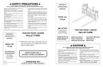
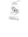
1
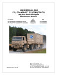
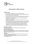
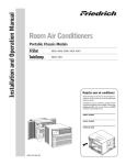
Field Pack-Up (FPU®) Series
USER MANUAL FOR
MWC
MODULAR WORKSHOP CONTAINER
User and General Purpose
Maintenance Manual
FPU® SERIES
PART NUMBER
NSN
MODULAR WORKSHOP CONTAINER (TAN)
15002028-T
8145-01-524-4030
MODULAR WORKSHOP CONTAINER (GREEN)
15002028-G
8145-01-524-4030
Version 001A, 25 Oct 2005
BOH Environmental, LLC
FPU Mobility Systems Division
4116C Walney Road, Chantilly, VA 20151
Ph: (703) 449-6020 Fax: (703) 449-6022
Field Pack-Up (FPU®) Series
THIS PAGE INTENTIONALLY LEFT BLANK
Field Pack-Up (FPU®) Series
BOH DATA PLATE
Located to the right of the entrance door
i
Field Pack-Up (FPU®) Series
TABLE OF CONTENTS
Section ................................................ Page
Section................................................ Page
BOH DATA PLATES ........................................... i
TABLE OF CONTENTS ..................................... ii
LIST OF ILLUSTRATIONS ............................... iii
LIST OF TABLES.............................................. iii
SAFETY SUMMARY......................................... iv
WARNING SUMMARY ..................................... vi
4.4 Operation of Roof Access Ladder ....... 11
4.5 MWC Entrance Door ........................... 12
4.6 Interior Door Lock................................ 13
4.7 Workshop Interior Components .......... 14
4.8 Interior Lighting System and Electrical
Operation…………………………
16
4.9 HVAC Heater/Air-Conditioned Unit ..... 19
4.10 Exterior Electrical Connections ......... 20
I.
INTRODUCTION AND
GENERAL INFORMATION
1.1 Introduction ............................................1
1.2 General Information...............................1
1.3 Special Tools & Test Equipment ...........2
II. MWC STANDARD CONFIGURATION
2.1 MWC INTERIOR MODULE TYPES &
CONFIGURATIONS ..................................3
III. PREPARATION FOR USE, STORAGE,
MOVEMENT AND SHIPMENT
3.1 Preparation for Use ...............................6
3.2 Preparation for Storage .........................6
3.3 Preparation for Movement .....................6
3.4 Preparation for Shipment.......................7
IV. MWC OPERATIONS
4.1 MWC Setup and Operation
Instruction..............................................9
4.2 Site Requirements .................................9
4.3 Preparing MWC Shipping/Storage for
Use ........................................................9
V. MWC MODULAR WORKBENCHES
5.1 Modular Workbenches ........................ 22
5.2 Drawer Replacement........................... 23
VI. MWC MAINTENANCE GUIDE
6.1 Cleaning, Lubrication and Preventative
Maintenance Checks and Services
(PMCS) ............................................... 24
6.2 Repairs ................................................ 26
6.3 Technical and Replacement Part
Information Sources............................ 26
6.4 Troubleshooting................................... 26
VII.
MWC ELECTRICAL DIAGRAMS
VIII. MWC PARTS LIST
8.1 Repair Parts List............................... 29
IX.
MWC WARRANTY
Warranty................................................. 30
ii
Field Pack-Up (FPU®) Series
LIST OF ILLUSTRATIONS
Figure .................................................. Page
Figure.................................................. Page
Figure 2.1-1 MWC Modules ...............................4
Figure 2.1-2 Interior Components Layout ..........5
Figure 3.4-1 MWC-Loaded Transport System ...8
Figure 4.3-1 Lifting / Tie Down Rings...............10
Figure 4.3-2 Ladders........................................11
Figure 4.4-1 Roof Access Ladder (MWC)........12
Figure 4.6-1 Door/Hand Rail ............................12
Figure 4.6-2 Door Lock ....................................13
Figure 4.6.3 Interior Door Lock ........................13
Figure 4.7-1 Interior Workshop ........................14
Figure 4.7-2 Slam Latches and Security Bars .15
Figure 4.7-3 Storage Weight Limits .................15
Figure 4.7-4 Uni-Strut Floor Tracks .................16
Figure 4.7-5 Desk and Cabinets ...................... 16
Figure 4.8-1 Lighting System, Exhaust Fan,
GFCI Outlets ............................................. 17
Figure 4.8-2 Front Interior Layout Diagram ..... 18
Figure 4.9-1 Rear Interior Layout Diagram...... 19
Figure 4.9-2 HVAC and Dust/Weather Cover.. 20
Figure 4.10-1 Exterior Electrical Connections . 21
Figure 5.1-1 Modular Workbench .................... 22
Figure 5.2-1 Drawer/Shelf Mounting................ 23
Figure 7.1-1 Internal Electrical Power
Diagram ..................................................... 27
Figure 7.1-2 External Electrical Power
Diagram ..................................................... 28
LIST OF TABLES
Table.................................................... Page
Table ................................................... Page
Table 3.4-1 MWC Container Load Certification
Specifications...............................................7
Table 6.1-1 Cleaning Procedures ....................24
Table 6.1-2 Lubrication Procedures.................25
Table 6.1-3 Preventative Maintenance Checks
and Services (PMCS) ................................25
Table 6.3-1 Technical and Replacement Part
Information Sources .................................. 26
Table 6.4-1 Troubleshooting Checks............... 26
Table 8.1-1 Replacement Parts List ................ 29
iii
Field Pack-Up (FPU®) Series
SAFETY SUMMARY
This warning summary contains general safety precautions and hazardous material warnings that must be
understood and applied during operation and maintenance of this equipment. Failure to observe these
warnings could result in serious injury or death.
GENERAL WARNINGS
HEAVY PARTS - heavy object on human figure shows that heavy parts present
a danger to life or limb.
HEAVY PARTS - heavy object pinning human figure against wall shows that
heavy, moving parts present a danger to life or limb.
HEAVY PARTS - hand with heavy object on top shows that heavy parts can
crush and harm.
HEAVY PARTS - foot with heavy object on top shows that heavy parts can crush
and harm.
SLICK FLOOR - wavy line on floor with legs prone shows that slick floor
presents a danger for slipping or falling.
HEAVY OBJECT - human figure stooping over heavy object shows physical
injury potential from improper lifting technique.
ELECTRICAL - electrical wire to arm with electricity symbol running through
human body shows that shock hazard is present.
ELECTRICAL - electrical wire to hand with electricity symbol running through
hand shows that shock hazard is present.
iv
Field Pack-Up (FPU®) Series
CRYOGENIC - hand in block of ice shows that the material is extremely cold and
can injure human skin or tissue.
FIRE - flame shows that a material may ignite and cause burns.
VAPOR - human figure in a cloud shows that material vapors present a danger to
life or health.
CHEMICAL - drops of liquid on hand shows that the material will cause burns or
irritation to human skin or tissue.
EYE PROTECTION - person with goggles shows that the material will injure the
eyes.
v
Field Pack-Up (FPU®) Series
WARNING SUMMARY
This warning summary contains general safety warnings and hazardous materials warnings that
must be understood and applied during operation and maintenance of this equipment. Failure to
observe these precautions could result in serious injury or death to persons using equipment.
WARNING
Do not allow the Modular Workshop Container (MWC) to swing if using an
overhead lift. Always ensure an appropriate sling is used in the lift. Always use
properly sized forklift, crane, or lifting device. Failure to comply could cause
injury to personnel or damage to the equipment.
WARNING
Use extreme caution when loading the MWC onto a FPU transport system or
other transport device. Forklift support or crane is required. Make sure all
container materials are properly seated, locked and secured. Failure to comply
could cause serious injury. Failure to follow proper connection to the transport
vehicle or transport device procedures may result in damage to the equipment or
injury or death to personnel.
Standard forklift principles apply when working with or on the MWC. When
working with ground guides during the loading or unloading of a MWC, never
move the MWC onto the FPU transport system or other transport vehicle while
the ground guide is between the forklift, MWC and the transport system or
vehicle. Serious injury could occur if the ground guide is pinned between the
forklift and the MWC. Forklift operators must maintain visual contact with their
ground guides at all time.
Always follow standard forklift procedures. A tilt hazard exists when forklift
operators try to lift a partially loaded MWC from the wrong side. Always lift a
MWC with the heavier side closest to the forklift operator. This places the
heavier part of the load back into the tines versus out on the tips. A tilt situation
exists when the heaviest part of the load is out on the tips of the tines, on uneven
ground, with forks fully extended, and while traveling. Operators should always
keep loads low and close to the forklift carriage. Operators should never travel
when the load is in the fork’s extended position.
WARNING
The MWC and its contents are heavy and could cause injury if interior equipment
drawers and shelves are not secured and locked in position. A tilt hazard exists
when the drawers or shelves inside of the MWC container are not locked down.
As a rule, always work on one drawer at a time. Never have more than one
drawer extended in the full open position at a time, especially if loaded.
Personnel should never stand on a drawer.
vi
Field Pack-Up (FPU®) Series
WARNING
Fall hazards exist when climbing onto or working from the top of the MWC.
Always maintain three points of contact to the ladder and container when
climbing onto the roof. Never move, step, or walk backwards when working on
top of the system. All movement should be in the forward direction. A fall can
occur if personnel lose concentration and step backwards off of the edge. Stand
erect only if necessary and only away from the edge. Working from a kneeling
position helps reduce the threat of a fall.
The MWC may be used to store various forms of oils, lubricants and other
potentially slippery substances. Keeping the inside floor of the containers clean
is important; nevertheless, always move with caution inside a MWC. Failure to
maintain cleanliness could cause a slip and injury.
WARNING
Overhead power lines and obstructions can cause serious injury to personnel or
damage to property. Forklift operators, truck drivers and ground guides should
always clear overhead when loading, unloading, or moving the MWC containers.
WARNING
To prevent electrical shock hazard, only trained and qualified personnel should
attempt to correct electrical discrepancies. Additionally, electrical power must be
disconnected before any electrical system work is performed.
WARNING
Protective gloves should be worn when handling metal parts in below freezing
temperatures. Failure to wear gloves may result in skin freezing to the metal
upon contact and cause tearing of the flesh when attempting to pull away from
the metal.
WARNING
Dry cleaning solvent is flammable and cannot be used near an open flame. Use
only in well-ventilated places and have a fire extinguisher available. Use of
protective clothing as directed in the product MSDS is required. Failure to
comply could result in injury or equipment damage. Do not allow cleaning
solvents or compounds to come in contact with door seals, covers, fabric, or
rubber components. Damage to these components will occur.
vii
Field Pack-Up (FPU®) Series
THIS PAGE INTENTIONALLY LEFT BLANK
Field Pack-Up (FPU®) Series
SECTION I
INTRODUCTION AND GENERAL INFORMATION
Field Pack-Up (FPU®) Series
THIS PAGE INTENTIONALLY LEFT BLANK
Field Pack-Up (FPU®) Series
SECTION I
INTRODUCTION AND GENERAL INFORMATION
1.1
INTRODUCTION
1.1.1
Purpose. This User Manual provides operational, safety and maintenance information for the
Modular Workshop Container (MWC) which is a series of containers and modules.
1.1.2
Manual Scope. This manual will cover safety, minor repair, suggested service and maintenance,
troubleshooting, and provides a parts list with illustrations to help operating personnel use the
system to its full capacity.
1.2
GENERAL INFORMATION
1.2.1
Descriptions. BOH Environmental’s Modular Workshop Container (MWC) is a durable,
workshop/office that can be adapted across the spectrum of military Family of Mobile Tactical
Vehicles (FMTV).
1.2.2
Container. The MWC system consists of a workshop and office with a wide range of optional,
easily installed interchangeable modular inserts.
1.2.3
Modules. There are standard workshop and office modules, and a wide range of specialized
equipment/supply module systems that will enable the customer to design a mobile package to
meet any requirement.
1.2.4
MWC System Benefits. The MWC system provides an air-conditioned/heated mobile workshop
with tool storage cabinets and an office workstation for technical references, maintenance and
repair record keeping. The Aluminum construction provides lightweight, long-term durability for
rugged use in the field. The MWC provides the operators with rapid set-up or takedown capability
for the quick deployment and relocation of the workshop. The combination of the MWC with the
FPU Transport System creates an asset that is readily mobile and has a detachable
stairway/ladder for access without removing the workshop from the transport system.
1.2.5
MWC Manufacturer’s Data Plate. MWC data plates identify the manufacturer’s part number,
serialization, contract and delivery order number and National Stock Number (NSN). They are
easily visible at the exterior ends of each container. Each container has a MWC data plate
unique by serial number. Further information with regard to the BOH line of products can be
found on the BOH web site.
www.bohenvironmental.com
Additionally, BOH can be reached at:
BOH Environmental, LLC
FPU Mobility Systems Division
Field Pack-Up (FPU®) Series 4116C Walney Road, Chantilly, VA 20151
Ph: (703) 449-6020 Fax: (703) 449-6022
1
Field Pack-Up (FPU®) Series
1.3
SPECIAL TOOLS AND TEST EQUIPMENT
1.3.1
Descriptions. A General Mechanics Tool Set (NSN 5180-01-454-3787) is sufficient to perform
minor repairs on the containers and modules.
Note: All hardware is standard thread and removed with a Counterclockwise rotation and
tightened with a Clockwise rotation.
Personnel performing electrical repairs and service should be certified electricians and have the
proper tools and test equipment.
Field Pack-Up (FPU®) Series
SECTION II
MWC STANDARD CONFIGURATION
Field Pack-Up (FPU®) Series
THIS PAGE INTENTIONALLY LEFT BLANK
Field Pack-Up (FPU®) Series
SECTION II MWC STANDARD CONFIGURATION
This section describes the primary interior components.
FPU® SERIES
MODULAR WORKSHOP CONTAINER (TAN)
MODULAR WORKSHOP CONTAINER (GREEN)
PART NUMBER
NSN
15002028-T
15002028-G
8145-01-524-4030
8145-01-524-4030
2.1
MWC INTERIOR MODULE TYPES & CONFIGURATIONS
2.1.1
Description/Certifications. The system consists of a standard workshop and office work station
with other optional modules available that may be added, or replace an existing module to
accommodate a specific tailored need by the military unit.
2.1.2
MWC Modules The standard modules include a workbench attached to the interior left side that
has a shelf module and a drawer module under a continuous metal top (1), a workbench attached
to the interior right side that has two drawer modules under a continuous metal top (2). These are
easily moved or repositioned via floor and wall uni-strut nut and bolt connection.
See Figure 2.1-1.
2.1.3
The MWC is also provided with left and right wall mounted file cabinets (3) with latch type doors
and a 3-section wall mounted file bin (4) with a net over the front.
See Figure 2.1-1.
2.1.4
The MWC is provided with a desk workstation, two lockable file cabinets (5) holding four drawers
mounted to the floor and wall with the same uni-strut fasteners. See Figure 2.1-1.
3
Field Pack-Up (FPU®) Series
Figure 2.1-1
MWC Modules
1
2
3
5
4
4
Field Pack-Up (FPU®) Series
Figure 2.1-2
Interior Components Layout
5
Field Pack-Up (FPU®) Series
THIS PAGE INTENTIONALLY LEFT BLANK
Field Pack-Up (FPU®) Series
SECTION III
PREPARATION FOR USE, STORAGE,
MOVEMENT AND SHIPMENT
Field Pack-Up (FPU®) Series
THIS PAGE INTENTIONALLY LEFT BLANK
Field Pack-Up (FPU®) Series
SECTION III
PREPARATION FOR USE, STORAGE, MOVEMENT, AND SHIPMENT
3.1
Preparation for Use
Review the Safety Summary prior to any MHE Movement, Service or Operation of the MWC
Container (Pages vii and viii).
Relatively level terrain, soil and weather conditions, mud, ice, snow and sand should be
considered when selecting a container staging site to insure the safety of operating personnel.
Refer to MWC Load Spec’s. Table 3.4-1.
WARNING
Falling Material
Hazard
WARNING
Electrical
Hazard
WARNING
Crush
Hazard
3.2
Preparation for Storage
3.2.1
All container materials should be removed and general cleaning and inspection should be
performed, removing debris that may inhibit proper operation of doors, drawers, and ladders.
See Cleaning Table 6.1-1.
3.2.2
Lubrication of all moving parts, devices, locks, latches, pins and hinges should be performed.
Note: Lubrication of the moving parts is recommended prior to long-term storage or shipment.
See Lubrication Table 6.1-2.
3.2.4
All racks, upright drawer and tray lock rods, poles and ladder should be securely locked in place
with pins and or straps prior to storing the MWC.
3.3
Preparation for Movement
3.3.1
All drawer and shelf material should be removed and general cleaning and inspection should be
performed, removing debris that may inhibit operation of the ladder, retractable drawers, shelves,
pins and other locking devices.
3.3.2
All locking devices, pins, ladder and cabinets should be swept or wiped clean of debris and
inspected to insure they function prior to securing the MWC. See Cleaning Table 6.1-1.
3.3.3
MWC equipment, racks, retractable drawers, safety chains and ladders should be securely locked
in place with straps or pins prior to moving the MWC.
3.3.4
MWC should be securely mounted and restrained to the transport vehicle using standard tie down
procedures.
6
Field Pack-Up (FPU®) Series
3.4
Preparation for Shipment
WARNING
Falling Material
Hazard
WARNING
Crush
Hazard
Consult the manufacturer’s data for Maximum Gross Weight for the MWC container. See
Table 3.4-1.
When transporting any material inside MWC, that material should be properly tied down
and secured.
Table 3.4-1
MWC Load Certifications Specifications
Nomenclature
Tare
Weight
Payload
Ground
Maximum
Capacity
Payload
Air
Certification
Inter-modal
MWC
3,300 lbs
N/A
5,000 lbs
5,000 lbs
N/A
N/A
7
Field Pack-Up (FPU®) Series
Figure 3.4-1
MWC Loaded on FPU Transport System
8
Field Pack-Up (FPU®) Series
THIS PAGE INTENTIONALLY LEFT BLANK
Field Pack-Up (FPU®) Series
SECTION IV
MWC OPERATIONS
Field Pack-Up (FPU®) Series
THIS PAGE INTENTIONALLY LEFT BLANK
Field Pack-Up (FPU®) Series
SECTION IV
MWC OPERATIONS
4.1.1
MWC Container Setup and Operation Instruction
This section provides step-by-step instructions for the download, set-up and moving of the MWC
containers. Review the Safety Summary prior to any MHE Movement, Service or Operation of the
Container on pages iv and v.
WARNING
During movement of any kind or if the container is dropped, contents may have
shifted; extreme care should be taken when opening the doors to prevent material
from falling on and injuring personnel.
4.2
Site Requirements
WARNING
If used in a ground-based operation, the MWC Container must be operated on level
ground and periodically checked for shifting from a level position. Use care when
first opening doors or draws as physical injury may occur. To maintain control,
consider the ground surface conditions for adequate traction such as mud, snow,
ice and sand.
CAUTION
Flood plane conditions should be considered. If in doubt, consult the operations
supervisor or commander.
4.3
Preparing MWC Shipping/Storage for Use
4.3.1
MWC Shipping/Storage The MWC is designed for use with a FPU-TS. It provides a highly
mobile platform with a MWC container ready for immediate use in most circumstances, and it has
the advantage of rapid setup and access without unloading the MWC as well as quick mobile
relocation.
CAUTION
The MWC is constructed of aluminum to conserve weight and should not be
stacked. It is not an ISO-configured or certified container and has no ISO corner
blocks. The MWC is provided with four large lifting rings (1) one at each top corner
for crane lifting operation. Additionally, there are four rings (2) provided to chain or
9
Field Pack-Up (FPU®) Series
cable tie-down the MWC to the FPU Transport System, FMTV transport vehicle or
flat bed trailer. See Figure 4.3-1.
There are two forklift pockets (3) on each side of the MWC for forklift movement.
See Figure 4.3-1.
There are also trap doors (4) on each side of the container that provide electrical
hook-up and are not to be used for lifting the container. See Figure 4.3-1
Figure 4.3-1
Lifting / Tie Down Rings
1
2
4
3
10
Field Pack-Up (FPU®) Series
4.3.2
MWC Entrance Ladder The MWC is equipped with two ladders, one ladder (1) for access to the
workshop door when the MWC is positioned on the FPU Transport System or other transport
vehicles, and a fixed roof ladder (2) See Figure 4.3-2.
Figure 4.3-2
Ladders
2
1
4.4
Operation of Roof Access Ladder
The roof access ladder consists of a fixed ladder (1) on the front of the MWC to the left of the
door. Access to the roof is required during MWC Sling Lift from, or to, the FPU-TS and other
transport vehicle. A fixed handrail (2) is provided for safe access to the roof to facilitate slinglifting operation. See Figure 4.4-1.
WARNING
Fall hazards that may result in injury or death exist when climbing onto, returning from or
working from the top of the container. Always maintain three points of contact with the
folding steps and roof when climbing onto the container. All movement should be in the
forward direction. Never move, step, or walk backwards when working on top of the
system. A fall can occur if the worker loses concentration and steps backwards off of the
edge. Stand erect only if necessary and only away from the edge. Working from a
kneeling position helps reduce the threat of a fall.
4.4.1
With the MWC loaded and secured on the rear of the transport vehicle, remove the Velcro
retaining strap (3) located at the bottom of the access ladder. Figure 4.4-1.
4.4.2
Unpin (2) the safety grab handle (1) and swing outward 90 degrees. Figure 4.6-1.
11
Field Pack-Up (FPU®) Series
4.4.3
Pin the safety grab handle (1) through the slot located in the center tub (4) of the grab handle.
Figure 4.6-1.
4.4.4
Lift the ladder upwards until clear of the top fixed step of the roof access ladder and remove.
4.4.5
Attach removable ladder to the mounting bracket (5) located at the bottom of the access door for
access to the inside of the MWC or the or the mounting bracket (6) located at the bottom of the
roof access ladder if roof access is desired. Figure 4.4-1.
Figure 4.4-1
Roof Access Ladder
(MWC)
2
3
1
4
6
5
4.5
MWC Entrance Door
4.5.1
Door/Hand Rail The MWC has a large handrail (1) that is locked in place by pins (2) that must be
unpinned and swung to its deployed position prior to attempting to open the door. Refer to
procedures in 4.4. The door is also provided with a securing strap (3) for windy conditions.
See Figure 4.6-1.
Figure 4.6-1
Door/Hand Rail
2
1
4
3
12
Field Pack-Up (FPU®) Series
4.5.2
Door locks The MWC has a robust lock system that consists of a large handle with a key (1) and
piston (2). When engaged, the piston (2) provides a positive locked position (3) to secure the door
handle. A door handle instruction plate (4) is provided on the door. See Figure 4.6-2.
4.5.3
The door handle operation is as follows:
1. To engage the interior door lock-blade (6), swing the exterior handle (5) downward then
return it to the center position; at this point the door may be key locked. See Figure 4.6-2.
2. To open the door and disengage the interior lock-blade (6), swing the handle (5) to the
upward OPEN position and return to center position. See Figure 4.6-2.
NOTE: Ensure the door is in the unlocked position before attempting to open or close.
Figure 4.6-2
Door lock
1
3
2
5
4
6
4.6 Interior Door Lock. The MWC door mechanism is design to allow exit while the exterior lock is
engaged. Pull door handle (2) upward to open. See Figure 4.6-3.
Figure 4.6-3
Interior Door Lock
1
2
13
Field Pack-Up (FPU®) Series
4.7 Workshop Interior Components (Standard Configuration)
Two modular Work cabinets (1) with See Figure 4.7-1
Fifteen rollout drawers (2) See Figure 4.7-1
Two fixed shelves (3) See Figure 4.7-1
Four wall mounted storage cabinets with doors (4) See Figure 4.7-1
Three wall-mounted cabinets with netting (6) See Figure 4.7-1
One desk with two filing cabinets (5) See Figure 4.7-1
Figure 4.7-1
Interior Workshop
6
5
4
1
3
4.7.1
2
The rollout drawers and shelves have slam latches (1) on either side to latch the drawer in the
closed position when not in use. There are additional security bars (2) secured by a linchpin and
lanyard (3) to insure drawers stay in their closed position during transit. See Figure 4.7-2
4.7.1.1 To operate drawers the restraint rods need to be removed.
4.7.1.2 To remove restraint rods (2) first remove the restraint rod retainer pins (3). See Figure 4.7.2.
4.7.2.3 Lift restraint rod (2) upward until it is clear of the bottom-securing slot and pull outward.
See Figure 4.7.2.
4.7.1.4 Store the restraint rods in a safe place. See Figure 4.7.2.
4.7.1.5 Grab both slam latches (1) and pull towards the center of the drawer and pull drawer outward
until slam latches are clear of the strike plate (4). See Figure 4.7.2.
14
Field Pack-Up (FPU®) Series
Figure 4.7-2
Slam Latches and Security Bars
3
2
1
4
3
CAUTION
Workbench drawers, shelves and cabinets have the following weight limitations:
Figure 4.7-3
Storage Weight Limits
15
Field Pack-Up (FPU®) Series
4.7.2
The modular work cabinets are affixed to the wall and floor by means of uni-strut nuts
and bolts in uni-strut tracks (1) that provides the option to move or exchange the work
cabinets within the workshop. See Figure 4.7-4.
Figure 4.7-4
Uni-Strut Floor Tracks
1
4.7.3
The workshop is provided with a work desk (1) with two lockable file cabinets (2) for
technical record keeping. There are also four wall cabinets (3) above each workbench
and three bookshelves (4) with nets to secure manuals and other record keeping
materials. See Figure 4.7-5. Note: For weight limitations chart, see Figure 4.7-3.
Figure 4.7-5
Desk and Cabinets
1
3
4
2
4.8 Interior Lighting System and Electrical Operation
4.8.1
The MWC is provided with 12 VAC overhead lighting (1) that may be pre-selected to white or red
lighting conditions. The bank of switches (2, 3 and 4) are located on the left side just inside the
door. See Figure 4.8-1 and 4.8-2.
4.8.2
The switch (2) on the right of the bank is used to select 110VAC workbench lighting from the
external power source. See Figure 4.8-1.
4.8.3
The two-position switch at the top (3) is for red or white light condition selection.
See Figure 4.8-1.
16
Field Pack-Up (FPU®) Series
4.8.4
The three-position switch (4) at the bottom of the bank of switches operates the door activation
switch (5). The three positions are as follows:
1. Up position DOOR ACTIVE. The door switch (5) is active. The Door switch (5) will activate
the Red condition lights when the door is open.
2. Center position OFF. The overhead lighting is off.
3. Down CONTINUOUS. The Door Switch (5) is now inactive and, if the overhead lighting
switch (3) is selected Red, it will be on continuous red. If the overhead lighting switch (3)
selection is White when the door is opened, the red lighting will override the White to a Red
Lighting condition. See Figure 4.8-1.
NOTE It is important to understand that the workbench lighting should be turned off when
red light conditions are desired, as it is a separate circuit and will not go to a red
condition.
4.8.5
The door is also provided with a switch (5) to activate the selection of red light when the door is
opened during red light conditions. See Figure 4.8-1.
4.8.6
The MWC is also provided with 110 VAC florescent lighting (6) above the workbenches that is
activated from the light switch (2). Each light fixture has an on/off switch. See Figure 4.8-1.
NOTE: The 110 VAC Florescent Light should not be used during red light conditions. The door
switch does not turn this light off and white light will escape if the door is opened.
4.8.7
The MWC is also provided with a bank of 110 VAC GFCI outlets (7) above each workbench for
electrical appliances, i.e. soldering tool. See Figure 4.8-1.
Figure 4.8-1
Lighting System, Exhaust Fan, GFCI Outlets
3
1
2
5
4
6
7
8
17
Field Pack-Up (FPU®) Series
Figure 4.8-2
Front Interior Layout Diagram
4.8.8
The MWC is provided with a non-filtered 120 VAC vent fan (8) located on the right just inside the
door to evacuate fumes or smoke from the work area during repair operations, i.e. soldering.
See Figure 4.8-1 and 4.8-2.
4.8.9
The load center circuit breaker box (2) is located against the rear wall center of the MWC.
See Figure 4.9-1 and 4.9-2.
NOTE: To open the load center circuit panel door, pull downward ½” to clear the top
cover then swing open.
18
Field Pack-Up (FPU®) Series
4.9
HVAC Heater/Air-Conditioned Unit
Figure 4.9-1
Rear Interior Layout Diagram
4.9.5
The MWC is provided with a Heater/Air-conditioned Unit (1) that is in a fixed position mounted
into a frame (6) that extends through the rear wall above the load center circuit breaker box (2).
See Figure 4.9-1 and 4.9-2.
4.9.6
The HVAC (1) has a Dust/Weather Cover (3) attached by snaps (4) and hook and pile fabric (5)
to protect it from adverse weather and dust during travel. See Figure 4.9-2.
19
Field Pack-Up (FPU®) Series
Figure 4.9-2
HVAC and Dust/Weather Cover
1
2
3
6
3
4.9.7
5
4
5
The weather cover (3) must be removed prior to operation of the HVAC.
See Figure 4.9-2.
CAUTION
Failure to remove the HVAC weather cover (3) will cause the unit to overheat. See Figure 4.9-2.
4.10 Exterior Electrical Connections
4.10.1 The MWC is provided with an external cable (1) for connection to the transport vehicle auxiliary
12VDC power for the overhead lighting system. See Figure 4.10-2.
4.10.1.1
Connect black wire to negative battery terminal. Connect white wire to positive battery
terminal.
NOTE: Connect both wires to the terminal post of a single battery in multiple battery
applications.
4.10.2 The MWC is also provided with an external cable (2) connection to an external generator for
20
Field Pack-Up (FPU®) Series
240VAC supply. The MWC is 110VAC, 60Hz, Single Phase, GFCI and workbench florescent
lighting. See Figure 4.10-2.
4.10.2.1
Connect wires as follows:
Black wire --- shore power line 1
Red wire------ shore power line 2
White wire---- shore power neutral
Green wire---- shore power ground
NOTE: This is standard residential coloring. A generator should have outputs labeled as
L1, L2, N, G or by color or both.
4.10.3 The cables are housed within protective compartments (3) at the bottom, to the rear of the forklift
pockets (4), on either side of the MWC. See Figure 4.10-2.
NOTE: The 240VAC (2) and the 12VDC (1) wire ends are (bare wire) open ends with no
connectors so the user may determine the type and style of connection required to a source such
as vehicle auxiliary power, battery pack, 12VAC battery charger, generator or 240VAC power
source. For the Phase wiring connection diagram, see Section VII, Figure 7. 1-1.
Figure 4.10-1
Exterior Electrical Connections
1
3
2
4
CAUTION
Do Not utilize the exterior wire compartments for forklift pockets; they are not to be
used for any lifting operation. Damage will occur.
21
Field Pack-Up (FPU®) Series
THIS PAGE INTENTIONALLY LEFT BLANK
Field Pack-Up (FPU®) Series
SECTION V
MWC MODULAR WORKBENCHES
Field Pack-Up (FPU®) Series
THIS PAGE INTENTIONALLY LEFT BLANK
Field Pack-Up (FPU®) Series
SECTION V
MWC MODULAR WORKBENCHES
5.1
Modular Workbenches
5.1.1
There are two types of MWC workbench modules mounted under a continuous metal top (1).
See Figure 5.1-1.
5.1.2
The module workbench on the interior right hand side of the MWC consists of two drawer type
modules (2). See Figure 5.1-1.
5.1.3
The module workbench on the interior left hand side of the MWC consists of one drawer type
module and one shelf type module (3). See Figure 5.1-1.
5.1.4
The modules are completely interchangeable and may be repositioned with the removal of the
drawers (2) or shelves (3) and loosening of uni-strut type nut and bolts (4) in the floor tracks (5)
and the back of the workbench. See Figure 5.1-1.
Figure 5.1-1
Modular Workbench
1
6
2
5
5.1.5
3
7
At this point the entire workbench may be moved, or the top may be removed to exchange the
drawer (1) or shelf type (2) module.
Caution
It is recommended that only the modules be exchanged and the workbenches
remain in their position to provide lighting. It is not recommended that the
florescent lighting (6) be moved because of the wiring structure.
22
Field Pack-Up (FPU®) Series
The floor tracks are there to provide an additional, optional work desk (7) or other BOH
optional modules.
5.2
Drawer Replacement
5.2.1
The drawers and shelves (1) of the MWC workbenches are held in place by eight screws (2) and
automotive Aveco clips (3) attached to the drawer/shelf slides (4). See Figure 5.2-1.
Figure 5.2-1
Drawer/Shelf Mounting
1
2
4
3
Left and right drawer slide assemblies
23
Field Pack-Up (FPU®) Series
SECTION VI
MWC MAINTENANCE GUIDE
Field Pack-Up (FPU®) Series
THIS PAGE INTENTIONALLY LEFT BLANK
Field Pack-Up (FPU®) Series
SECTION VI
MWC MAINTENANCE GUIDE
Review the Safety Summary on pages iv through vii prior to any MHE Movement,
Service or Operation of the MWC.
6.1
Cleaning, Lubrication and Preventative Maintenance Checks and Services (PMCS)
WARNING
Chemical Hazard
6.1.1
Cleaning. Cleaning is performed after an operational event and periodically if stored/ staged outside
to insure the containers, modules and accessories will perform as designed. Cleaning also assists in
the performance of maintenance and insures the good operating condition of the MWC.
See Table 6.1-1.
Table 6.1-1
Cleaning Procedures
SURFACE
OIL/GREASE
SALT/MUD/DIRT/
DEBRIS
Exterior and Interior
Surfaces (All)
Detergent, Water,
Rags
Soapy Water, Brush,
Rags
Fabric Safety Straps
Detergent, Water,
Rags
Soapy Water, Brush
N/A
Storage Box Seals
and Gaskets
Damp and Dry Rags
Damp and Dry Rags
N/A
MWC Floor
Detergent, Water,
Rags
Soapy Water, Brush,
Rags
Ladder and Door
Hinges, Drawer/Shelf
Glides, and Rails,
Floor Tracks
N/A
Brush, Rag and
lubricate as needed to
ensure rails travel freely
Dry Rags, Coat with Lube
Oil or Spot Paint
Corrosion Removal
Compound and Wire Brush,
Dry Rags and Lubricate as
needed
RUST/CORROSION
Corrosion Removal
Compound and Wire Brush,
Dry Rag, Coat with Lube Oil
or Spot Paint
24
Field Pack-Up (FPU®) Series
6.1.2 Lubrication. Lubrication is performed after cleaning, periodic events and prior to storage to
insure good operation and prevention of corrosion of moving parts. See Table 6.1-2.
Table 6.1-2
Lubrication Procedures
FLUID
LUBRICANT
CAPACITIES
EXPECTED
TEMPERATURES
OE/HDO
As Required
All Temperatures
Monthly or as
Required if under
Adverse Situations
Storage Box door
Locks, Hinges,
Handles
Lubricating Oil,
General
Purpose
Preservative
As Required
All Temperatures
Monthly or as
Required if under
Adverse Situations
Local Lube Points,
Door Hand Rail
Hinge Points
Dry Lubricant
As Required
All Temperatures
Monthly or as
Required if under
Adverse Situations
USAGE
Drawer/Shelf
Slides, Pins, Floor
Locking
Mechanisms
6.1.2
INTERVAL
PMCS. Preventative Maintenance Checks and Services (PMCS) should be performed at the
established periods in order to insure smooth and proper operation of the equipment in the
system. See Table 6.1-3.
Table 6.1-3
Preventive Maintenance Checks and Services (PMCS)
PMCS B (Before) D (During) A (After) W (Weekly) M (Monthly)
# B
D
A
1 *
*
*
W M INSPECTION ITEM AND PROCEDURE
Storage Box Doors, Walls, MWC Ladder
Check all doors, walls and ladder steps for cracks,
dents, holes, or loose/missing hardware.
*
2
*
3
*
*
*
Lubricate hinges and locks as required.
Exterior
Check all exterior surfaces for cracks and dents that
effect the operation of the MWC.
Check for accumulations of dirt, debris, ice, snow, or
salt.
Clean as required. Check MWC floor for dirt and
debris. Clean with broom or rags as required.
Check MWC Drawer/Shelf Lock devices for cracks
or missing latches, pins and lanyards.
Check Ladder and Hand Rail for damaged or
missing linchpins and lanyards, hook and pile
straps.
Replace or tighten as necessary.
Data Plates
Check plates for legibility, damage and/or absence.
Clean with water and rags. Replace as needed.
EQUIPMENT NOT
READY/AVAILABLE
IF
Missing doors,
punctures, damage
that would cause
hazard or injury
Damage that would
cause malfunction of
the MWC working
systems such as lock
down devices that
would cause injury.
Missing or damaged
pins that would cause
injury by not securing
the door, ladder or
safety Hand Rail.
Replace any missing
or damaged pins. ?
Missing data that will
impair maritime
shipment.
25
Field Pack-Up (FPU®) Series
6.2
Repairs
Repair, adjustment and replacement of parts can be accomplished with a General Mechanic’s
Tool set (NSN 5180-01-454-3787).
6.3
Technical and Replacement Part Information Sources
Table 6.3-1
Technical and Replacement Part Information Sources
FUNCTION
HVAC
BODY REPAIR
& WELDING
BOH
EQUIPMENT
REPACEMENT
6.4
TECH MANUAL & TITLE
TWINTEMP MODEL EM18J34B TECH
WEB LIBRARY
FRIEDRICH OPERATING GUIDE &
INSTALLATION INSTRUCTION
LOCATED IN THE FILE CABINET
TM9-237
Welding Theory and Application
TM9-510
Metal Body Repair and Related
Operation
PARTS LIST SECTION VIII, PAGE 29.
MFG.
WEB SITE / ADDRESS & PHONE
NUMBER
HTTP/WWW.FRIEDRICH.COM/PDF/
WWW.LOGSA.COM
PHONE (703) 449-6020 FAX (703) 4496022
Troubleshooting
Review the Safety Summary prior to any MHE Movement, Service or Operation of the MWC on pages iv
through vii.
Table 6.4-1
Troubleshooting Checks
FUNCTION
MWC Operation
Section 4.3
Workbench drawers
will not open
Fan will not operate
HVAC is overheating
No Electrical Power
CHECKS
1. Insure the material stored inside is not obstructing the drawer operation.
1. Check and reset fan circuit breaker.
1. Insure the weather cover has been removed.
2. Inspect the filter and replace if necessary.
3. Inspect the Freon charge.
4. For other conditions consult the HVAC Website. See Table 6.3-1
1. Insure that the external electrical power source or generator is properly
connected, operating and grounded, i.e. power generator or extension cord to a
domestic facility AC power source.
2. Insure the power connection cables make firm connection. See Section VII
3. Check and reset circuit breakers.
26
Field Pack-Up (FPU®) Series
THIS PAGE INTENTIONALLY LEFT BLANK
Field Pack-Up (FPU®) Series
SECTION VII
MWC ELECTRICAL DIAGRAMS
Field Pack-Up (FPU®) Series
THIS PAGE INTENTIONALLY LEFT BLANK
Figure 7.1-1
Internal Electrical Power Diagram
27
Figure 7.1-2
External Electrical Power Diagram
28
Field Pack-Up (FPU®) Series
SECTION VIII
MWC PARTS LISTS
Field Pack-Up (FPU®) Series
THIS PAGE INTENTIONALLY LEFT BLANK
Field Pack-Up (FPU®) Series
SECTION VIII
MWC PARTS LIST
8.1
Replacement Parts List
Table 8.1-1
Replacement Parts List (The BOH CAGE Code is 1NSG3)
FIG. ITEM
PAGE
20
17
11
12
12
12
4
4
4
4
4
4
4
4
15
15
16
16
4
10
4.9-2 (1)
4.8-1 (8)
4.3-2 (1)
4.6-1 (3)
4.6-1 (1)
4.4-1
2.1-2
2.1-2
2.1-2
2.1-2
2.1-2
2.1-2
2.1-2
2.1-2
4.7-2 (2)
4.7-2 (2)
4.7-5 (3)
4.7-5 (4)
2.1-2
4.3-1 (1,2)
ITEM
HVAC Model EM18 Twin Temp
Vent Fan
Ladder (removable)
Door Strap
Ladder Hand Rail (swing)
Ladder Strap
Drawer 4” deep
Drawer 6” deep
Workbench Top
Desk Top
Drawer 4” Dividers
Drawer 6” Dividers
Shelf sliding (workbench)
Pin Assembly, Shelf Restraint
Restraint Rod, Drawer
Pin, Restraint Rod
Book Shelf
Cargo Net
File Cabinet
Corner Lifting Ring
CAGE
MFG.
89338
1NSG3
1NSG3
1NSG3
1NSG3
1NSG3
1NSG3
1NSG3
1NSG3
1NSG3
1NSG3
1NSG3
1NSG3
1NSG3
1NSG3
1NSG3
1NSG3
1NSG3
1NSG3
1NSG3
PART NUMBER
EM18J34B
94400308
16335051
16335037
16335035
16335055
16335065
16335060
16332029
16332531
16332007
16332003
16332026
16332111
16332023
15120668
16332540
15990115
91020303
46500132
29
Field Pack-Up (FPU®) Series
THIS PAGE INTENTIONALLY LEFT BLANK
Field Pack-Up (FPU®) Series
SECTION IX
MWC WARRANTY
Field Pack-Up (FPU®) Series
THIS PAGE INTENTIONALLY LEFT BLANK
Field Pack-Up Units (FPU®) Series
Boh Environmental, L.L.C
MANUFACTURER’S LIMITED WARRANTY TERMS
Boh Environmental, LLC (BOH) warrants that the Products, including the Field Pack-Up (FPU
Systems) and other Containerized Mission Systems, it manufactures shall be free from defects in
materials and workmanship for a period of one year from date of purchase when normally used
and operated by the Customer. Unused Product containing missing or defective components shall
be returned within the warranty period, with proof of purchase, to BOH with transportation
charges prepaid. BOH, at its option, shall supply a replacement item(s) or refund the purchase
price of the Product. BOH will determine, at its sole discretion, that the claim is a valid warranty
item. If so, BOH will pay costs (actual transportation plus handling charge) for shipping of the
replacement item, when this option is selected.
This warranty is void if Products have been damaged by the Customer as the result of improper
or unreasonable use, or other causes not arising out of defects in material or workmanship. The
warranty is also void if the Product has at any time been stored or used other than in accordance
with the directions set out in the literature relating to the Product. BOH makes no other warranty
or representation concerning the Products except that each will meet the performance
specifications set forth in the literature relating to the Product. There are no further warranties,
including any warranty of merchantability or fitness for a particular purpose covering the
Product.
BOH will, at its option, either (1) credit user in the amount paid for any Product which does not
perform to these specifications, or (2) replace such Product, provided user so notifies BOH
within twelve (12) months of the Products purchase date. BOH shall not be responsible for any
consequential damages to user arising as a result of such performance. The Customer will return
the item at their cost, if required. BOH may elect to have its representative inspect the item to
validate the claim.
Other product components included in the fabrication of items purchased under contract (e.g. air
conditioners and generators) that are not manufactured by Boh Environmental are warranted by
their individual manufacturer. Copies of such warranties are supplied with the finished Product
or are available through Boh Environmental.
30
Field Pack-Up Units (FPU®) Series
www.bohenvironmental.com
BOH Environmental, LLC
FPU Mobility Systems Division
4116C Walney Road
Chantilly, VA 20151
BOH FPU Systems
Telephone (703) 449-6020 / Fax (703) 449-6022