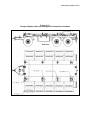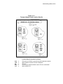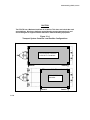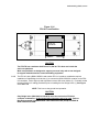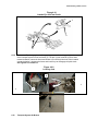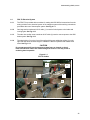
1
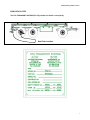
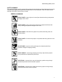
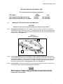
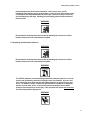
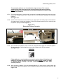
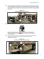
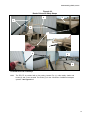
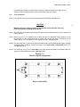
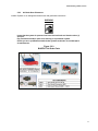
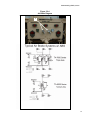
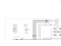
USER MANUAL FOR
FPU TRANSPORT SYSTEM (FPU-TS)
User and General Purpose
Maintenance Manual
FPU® SERIES
FPU TRANSPORT SYSTEM (FPU-TS) TAN
FPU TRANSPORT SYSTEM (FPU-TS) GREEN
Version 001A, 30 Oct 05
PART
NUMBER
15002022-T
15002022-G
NSN
NOT ASSIGNED
NOT ASSIGNED
BOH Environmental, LLC
FPU Mobility Systems Division
4116C Walney Road, Chantilly, VA 20151
Ph: (703) 449-6020 Fax: (703) 449-6022
Field Pack-Up (FPU®) Series
THIS PAGE INTENTIONALLY LEFT BLANK
Field Pack-Up (FPU®) Series
SECTION I
INTRODUCTION AND GENERAL INFORMATION
Field Pack-Up (FPU®) Series
BOH DATA PLATES
The FPU TRANSPORT SYSTEM (FPU-TS) provides a 31,000 lb. load capacity.
Data Plate Location
i
Field Pack-Up (FPU®) Series
TABLE OF CONTENTS
Section ................................................ Page
BOH DATA PLATES ........................................... i
TABLE OF CONTENTS ..................................... ii
LIST OF ILLUSTRATIONS ............................... iii
LIST OF TABLES.............................................. iii
SAFETY SUMMARY......................................... iv
WARNING SUMMARY ..................................... vi
I.
INTRODUCTION AND GENERAL
INFORMATION
1.1 Introduction ............................................1
1.2 General Information...............................1
1.3 Special Tools & Test Equipment ...........1
II. BOH FPU-TS PRODUCT LINE
2.1 Transport System Load Configurations.2
III. PREPARATION FOR USE, STORAGE,
MOVEMENT AND SHIPMENT
3.1 Preparation for Use .............................10
3.2 Preparation for Storage .......................10
3.3 FPU-TS Backing Procedure ................10
3.4 Preparation for Movement ...................11
3.4 Preparation for Shipment.....................12
IV. TRANSPORT SYSTEM and
CONTAINER OPERATIONS
4.1 FPU-TS Setup and Operation
Instruction............................................15
4.2 Site Requirements ...............................15
4.3 Preparing FPU-TS for Shipping/Storage
Systems for Use..................................16
4.4 Transport System Access Ladder .......17
4.5 Connecting Bridge Locks for a FPU-8 to
BOH-CARGO-6 to FPU-8
Combination of Containers ........................18
ii
Field Pack-Up (FPU®) Series
Section ................................................ Page
4.6 Connecting FPU-8-2 and BOH CARGO
12-1 Combination and Horizontal
Inter-Connectors .................................23
4.7 Deploying the Retractable Platforms...25
4.8 The Safety Work Area Border Set-Up .28
4.9 Pintle and Lunette Eye ........................30
4.10 Transport System Air Brakes.............31
4.11 Tires and Wheels...............................32
V. FPU TRANSPORT SYSTEM (FPU-TS)
MAINTENANCE GUIDE
5.1 Cleaning, Lubrication and Preventative
Maintenance Checks and Services
(PMCS) ......................................................34
5.2 Minor Repairs ......................................36
5.3 Technical Information and Replacement
Part Sources .......................................39
5.4 Troubleshooting...................................40
VI. FPU TRANSPORT SYSTEM (FPU-TS) ELECTRICAL DIAGRAM
6.1 FPU-TS Electrical System ...................42
VII. FPU TRANSPORT SYSTEM PARTS LIST
7.1 Repair Parts List ..................................43
VIII.FPU TRANSPORT SYSTEM (FPU-TS) WARRANTY
8.1 Warranty ..............................................44
iii
Field Pack-Up (FPU®) Series
LIST OF ILLUSTRATIONS
Figure .................................................. Page
Figure.................................................. Page
Figure 2.1-1 Work Area Platforms .....................2
Figure 2.1-2 Transport System and Load
Configuration Connection Locations............3
Figure 2.1-3 Transport System Load Location
Stencils ........................................................4
Figure 2.1-4 Transport System Container Load
Position Configurations................................5
Figure 2.1-5 Transport System FPU-8-2 and the
BOH-CARGO-12 Container Load Position..6
Figure 2.1-6 FPU-8-2 Load Position ..................7
Figure 2.1-7 Trailer Top View with Bridge Lock
Locations, FPU 8/6/8 Load Position ............8
Figure 2.1-8 Bridge Lock Installed .....................9
Figure 3.3-1 FPU-TS Mechanical Backing Locks
and Pins.....................................................11
Figure 3.5-1 Lock-Down Locations ..................14
Figure 4.1-1 Air Break Bleeders.......................15
Figure 4.3-1 ISO Twist Locks/Tie-downs (FPUTS) .............................................................17
Figure 4.4-1 Retractable Ladder (FPU-TS)......18
Figure 4.5-1 Bridge Lock and Tandem
Interlocking Containers..............................20
Figure 4.5-2 Roof Access System ...................21
Figure 4.5-3 Bridge Lock..................................22
Figure 4.5-4 Bridge Lock Installed ................... 23
Figure 4.6-1 Horizontal Inter-Connector .......... 24
Figure 4.6-2 FPU Retractable Steps................ 24
Figure 4.7-1 Retractable Platform Operational
Step 1 ........................................................ 26
Figure 4.7-2 Retractable Platform Operational
Step 2 ........................................................ 27
Figure 4.7-3 Retractable Platform Operational
Step 3 ........................................................ 27
Figure 4.7-4 Retractable Platform Access
Ladder Step 4............................................ 28
Figure 4.8-1 Safe Work Area Poles and Border
Straps Step 5............................................. 28
Figure 4.8-2 Border Poles and Safety Straps
Step 6 ........................................................ 30
Figure 4.9-1 Lunette Eye and Tow Pintle ........ 31
Figure 4.9-2 Leveling Jack............................... 31
Figure 4.10-1 Air Brake Connections............... 32
Figure 4.11-1 Wheel & Lug Nut Arrangement . 33
Figure 5.2-2 Tail and Running Lights............... 36
Figure 5.2-3 BLUEDOT Air Brake Parts .......... 37
Figure 5.2-4 Air Brake Diagram ....................... 41
Figure 6.1-1 FPU-TS Electrical System........... 42
LIST OF TABLES
Table.................................................... Page
Table ................................................... Page
Table 3.5-1 FPU-TS Transported Material Load
Specifications.............................................12
Table 3.5-2 FPU-TS Container Load
Specifications.............................................12
Table 3.5-3 Trailer Performance Data .............13
Table 5.1-1 Cleaning Procedures ....................34
Table 5.1-2 Lubrication Procedures.................35
Table 5.1-3 PMCS ........................................... 35
Table 5.3-1 Technical and Replacement Part
Information Sources .................................. 39
Table 5.4-1 Troubleshooting Checks............... 40
Table 7.1-1 Repair Parts List FPU-TS............. 43
iv
Field Pack-Up (FPU®) Series
SAFETY SUMMARY
This warning summary contains general safety precautions and hazardous material warnings that must be
understood and applied during operation and maintenance of this equipment. Failure to observe these
warnings could result in serious injury or death.
GENERAL WARNINGS
HEAVY PARTS - heavy object on human figure shows that heavy parts present
a danger to life or limb.
HEAVY PARTS - heavy object pinning human figure against wall shows that
heavy, moving parts present a danger to life or limb.
HEAVY PARTS - hand with heavy object on top shows that heavy parts can
crush and harm.
HEAVY PARTS - foot with heavy object on top shows that heavy parts can crush
and harm.
SLICK FLOOR - wavy line on floor with legs prone shows that slick floor
presents a danger for slipping or falling.
HEAVY OBJECT - human figure stooping over heavy object shows physical
injury potential from improper lifting technique.
ELECTRICAL - electrical wire to arm with electricity symbol running through
human body shows that shock hazard is present.
ELECTRICAL - electrical wire to hand with electricity symbol running through
hand shows that shock hazard is present.
v
Field Pack-Up (FPU®) Series
CRYOGENIC - hand in block of ice shows that the material is extremely cold and
can injure human skin or tissue.
FIRE - flame shows that a material may ignite and cause burns.
VAPOR - human figure in a cloud shows that material vapors present a danger to
life or health.
CHEMICAL - drops of liquid on hand shows that the material will cause burns or
irritation to human skin or tissue.
EYE PROTECTION - person with goggles shows that the material will injure the
eyes.
vi
Field Pack-Up (FPU®) Series
WARNING SUMMARY
This warning summary contains general safety warnings and hazardous materials warnings that must be
understood and applied during operation and maintenance of this equipment. Failure to observe these
precautions could result in serious injury or death to persons using equipment.
WARNING
Do not allow the system to swing if using an overhead lift. Always ensure an
appropriate sling is used in the lift. Always use properly sized forklift, crane, or
lifting device. Failure to comply could cause injury to personnel or damage to the
equipment.
WARNING
Always insure the FPU-TS brake system has been disengaged and the transport
system is unable to roll freely prior to, loading the transport system.
Use extreme caution when connecting Field Pack-Up Unit (FPU) containers into
a combination system. Forklift support is required. Make sure all container
connectors are properly seated and locked securely. Failure to comply could
cause serious injury. Failure to follow proper connection procedures may result
in damage to the equipment.
Standard forklift principles apply when working with or on the FPU container.
When working with ground guides during the loading or unloading of a module,
never move the module into the FPU container while the ground guide is
between the fork, module, and the FPU container. Serious injury could occur if
the ground guide is pinned between the forklift and the FPU container. Forklift
operators must maintain visual contact with their ground guides at all times.
Always follow standard forklift procedures. A tilt hazard exists when forklift
operators try to lift a partially loaded FPU container from the wrong side. Always
lift a container with the heavier side closest to the forklift operator. This places
the heavier part of the load back into the tines versus out on the tips. A tilt
situation exists when the heaviest part of the load is out on the tips of the tines,
on uneven ground, with forks fully extended, and while traveling. Operators
should always keep loads low and close to the forklift carriage. Operators should
never travel when the load is in the fork’s extended position.
WARNING
The FPU containers and their contents are heavy and could cause injury if they
fall onto or strike personnel.
WARNING
Fall hazards exist when climbing onto or working from the top of a FPU container
during crane lifting operation. Always maintain three points of contact to the
ladder and container when climbing onto the container. Never move, step, or
walk backwards when working on top of the system. All movement should be in
the forward direction. A fall can occur if personnel lose concentration and step
backwards off of the edge. Stand erect only if necessary and only away from the
edge. Working from a kneeling position helps reduce the threat of a fall.
The FPU containers may be used to store various forms of oils, lubricants, and
other potentially slippery substances. Keeping the top-working surface of the
FPU transport system clean is important; nevertheless, always move with caution
vii
Field Pack-Up (FPU®) Series
on top of FPU transport system. Failure to maintain clean work surfaces could
cause a slip and injury.
WARNING
The removable platforms are heavy and awkward to handle by a single person.
The installation of these items is a two-person operation.
WARNING
Overhead power lines and obstructions can cause serious injury or damage to
property. Forklift operators, truck drivers, and ground guides should always clear
overhead when loading, unloading, or moving the FPU transport system.
WARNING
To prevent electrical shock hazard, only trained and qualified personnel should
attempt to correct electrical discrepancies. Additionally, electrical power must be
disconnected before any electrical system work is performed.
WARNING
Protective gloves should be worn when handling metal parts in below freezing
temperatures. Failure to wear gloves may result in skin freezing to the metal
upon contact and cause tearing of the flesh when attempting to pull away from
the metal.
WARNING
Dry cleaning solvent is flammable and cannot be used near an open flame. Use
only in well-ventilated places and have a fire extinguisher available. Use of
protective clothing as directed in the product MSDS is required. Failure to
comply could result in injury to personnel or equipment damage. Do not allow
cleaning solvents or compounds to come in contact with door seals, covers,
fabric, or rubber components. Damage to these components will occur.
viii
Field Pack-Up (FPU®) Series
THIS PAGE INTENTIONALLY LEFT BLANK
ix
Field Pack-Up (FPU®) Series
SECTION I
INTRODUCTION AND GENERAL INFORMATION
x
Field Pack-Up (FPU®) Series
SECTION I INTRODUCTION AND GENERAL INFORMATION
1.1
INTRODUCTION
1.1.1
Purpose. This User Manual provides operational, safety and maintenance information for the
FPU TRANSPORT SYSTEM (FPU-TS).
1.1.2
Manual Scope. This manual will cover safety, minor repair, suggested service and maintenance,
troubleshooting, and provides a parts list with illustrations to help the operating personnel use the
system to its full capacity.
1.2
GENERAL INFORMATION
1.2.1
Descriptions. BOH Environmental’s Field Pack-Up FPU TRANSPORT SYSTEM (FPU-TS) is a
durable, transport system that can be adapted across the spectrum of military Family of Mobile
Tactical Vehicles (FMTV) and a wide range of other trucks and towing vehicles.
1.2.2
Containers. The system consists of a FPU TRANSPORT SYSTEM with a flexible ability to secure
wide range single FPUs or 20 foot FPU container combinations, i.e. FPU-8-2 and BOH-CARGO12, FPU-8-2 with a BOH-CARGO-6 and another FPU-8-2 and other BOH containers such as the
MWC, CCC, EWCC as well as any 20 foot ISO configured container.
1.2.3
FPU TRANSPORT SYSTEM Benefits. FPU TRANSPORT SYSTEM provides
extendable/retractable platforms that when deployed give container operators easy access to the
container doors and stored material without removing the containers from the trailer. The FPU-TS
allows for fast deployment with very small set-up and takedown time for rapid change in location
when needed, with the ability to access a variety of container combinations without removing the
containers from the trailer.
1.2.4
FPU TRANSPORT SYSTEM (FPU-TS) Manufacturer’s Data Plate. The FPU-TS data plate
identifies the manufacturer’s part number, serialization, contract and delivery order number and
National Stock Number (NSN). The FPU-TS data plates are unique by serial number for the
chaise and the front-tow Pintle structure. Further information on the BOH line of products can be
found on the BOH web site: www.bohenvironmental.com.
1.3
SPECIAL TOOLS AND TEST EQUIPMENT
1.3.1
Descriptions. A General Mechanics Tool Set (NSN 5180-01-454-3787) is sufficient to perform
minor repairs on the containers and modules.
NOTE: All hardware, bolts, jam nuts, and screws are loosened with a counterclockwise
rotation. All hardware, bolts, jam nuts, and screws are tightened with a clockwise rotation
with the exception of the wheel lug nuts. Review Section 4.11 TIRES and WHEELS.
Field Pack-Up (FPU®) Series
WARNING
Personnel performing electrical repairs and service should be certified electricians and
have the proper tools and test equipment.
WARNING
Personnel performing Air Break repairs and service should be certified in basic
pneumatics and have the proper tools and test equipment.
www.bohenvironmental.com
Additionally, BOH can be reached at:
BOH Environmental, LLC
FPU Mobility Systems Division
4116C Walney Road, Chantilly, VA 20151
Ph: (703) 449-6020 Fax: (703) 449-6022
Field Pack-Up (FPU®) Series
THIS PAGE INTENTIONALLY LEFT BLANK
Field Pack-Up (FPU®) Series
SECTION II
BOH FPU-TS PRODUCT LINE
Field Pack-Up (FPU®) Series
SECTION II BOH FPU-TS PRODUCT LINE
This section describes the following components:
FPU® SERIES
FPU TRANSPORT SYSTEM (FPU-TS) TAN
FPU TRANSPORT SYSTEM (FPU-TS) GREEN
2.1
PART
NUMBER
15002022
15002022
NSN
NOT ASSIGNED
NOT ASSIGNED
TRANSPORT SYSTEM AND LOAD CONFIGURATIONS
CAUTION
Review the entire section 4 prior to loading any containers on the FPU-TS.
2.1.1
Description/Certifications. The FPU Transport System provides a 31,000 lb. load capacity,
extendable/retractable work area platforms (1) that when deployed give the FPU operators easy
access to the container side doors and stored material without removing the containers from the
transport trailer. See Figure 2.1-1.
Figure 2.1-1
Work Area Platforms
1
1
2.1.2
Load configurations. The FPU-TS consists of a FPU Transport System with flexible ability to
securely transport a wide range of Field Pack-Up (FPU) Systems i.e. FPU-20-1, FPU-20-2, FPU8-2 with BOH-CARGO-12, FPU-8-2 with BOH-CARGO-6 and another FPU-8-2 connected and
other BOH containers such as the MWC, CCC, EWCC, and DC-12 DECON as well as any 20
foot ISO configured containers. See Figures 2.1-4, 2.1-5, 2.1-6 and 2.1-7.
2.1.3
Load stenciling. The floor of the FPU-TS is stenciled at the connection points (1) B thru E for
each optional load configuration. See Figures 2.1-2 and 2.1-3.
CAUTION
Maintain proper air pressure (written in raised letters on the side wall of the tire)
prior to movement or loading of the FPU-TS. Check and inflate with the FPU-TS
unloaded. Do not over-inflate.
2
Field Pack-Up (FPU®) Series
Figure 2.1-2
Transport System and Load Configuration Connection Locations
Side View
Field Pack-Up (FPU®) Series
Figure 2.1-3
Transport System Load Location Stencils
Location Stencils translate as follows:
20-2
12/8
8-2
8/6/8
12-1
=
=
=
=
=
FPU-20, CCC, EWCC, or any 20-foot ISO configured container
BOH-CARGO-12 with a FPU-8-2 combination
FPU-8-2
FPU-8-2 with a BOH-CARGO-6 and a FPU-8-2 combination
BOH-CARGO-12-1
Field Pack-Up (FPU®) Series
CAUTION
The FPU-TS has a Maximum load limit of 31,000 lbs. This does not include the work
area platforms. Work area platforms are designed to support personnel only and
are not designed to support stacked material or material handling equipment.
Figure 2.1-4
Transport System Container Load Position Configurations
FPU-20 Series Containers
or ISO 20 Ft. Containers
Detail E
Detail B
BOH-CARGO-12
Container
Detail C
2.1.4
Detail E
Field Pack-Up (FPU®) Series
Connection of the FPU-8-2 and the BOH-CARGO-12 containers require four ISO Horizontal InterConnectors (1). For details review the entire Section 4 Loading procedures of this manual,
specifically ISO Horizontal Inter-Connectors (1) prior to loading or unloading the container
combination.
CAUTION
This is an on-the-ground-level operation. Review the BOH FPU Container manual for this
operation. See Fig. 4.5-1.
Figure 2.1-5
Transport System FPU-8-2 and the BOH-CARGO-12 Container Load Position
FPU-8-2
Container
Detail B
BOH-CARGO-12
Container
Detail E
Adjuster
Field Pack-Up (FPU®) Series
Figure 2.1-6
FPU-8-2 Load Position
FPU-8-2
Container
Detail C
Detail D
CAUTION
The FPU-TS has a maximum load limit of 31,000 lbs. This does not include the
work area platforms.
Work area platforms are designed to support personnel only and are not designed
to support stacked material or material handling equipment.
2.1.5
The FPU-8-2 with a BOH-CARGO-6 and another FPU-8-2 container combination requires
installation of eight Bridge Lock devices (1) to connect the BOH-CARGO-6 container to the FPU8-2 containers, via the eight top and eight bottom center ISO corner blocks (2). For details review
the entire Section 4 Loading procedures prior to installing the four Bridge Locks (1). See Figure
2.1-7 and 2.1-8
NOTE: This is an on-the-ground-level operation.
CAUTION
Only Bridge locks (NSN 8145-01-523-4079) are to be used on the FPU 8/6/8
container combination. No Horizontal Inter-Connectors are to be used. Refer to
Boh Environmental’s USER MANUAL FOR FIELD PACK-UP (FPU®) SYSTEMS &
BOH CARGO SYSTEMS.
Field Pack-Up (FPU®) Series
Figure 2.1-7
Transport System Top View with Bridge Lock Locations
FPU 8/6/8 Load Position See 2.1-2
1
Bridge locks
required
FPU-8-2
Container
BOH-CARGO6 Container
FPU-8-2
Container
Bridge locks
required
Detail B
2
Detail E
Field Pack-Up (FPU®) Series
Figure 2.1-8
Bridge Lock Installed
9
Field Pack-Up (FPU®) Series
THIS PAGE INTENTIONALLY LEFT BLANK
Field Pack-Up (FPU®) Series
SECTION III
PREPARATION FOR USE, STORAGE,
MOVEMENT AND SHIPMENT
Field Pack-Up (FPU®) Series
SECTION III
PREPARATION FOR USE, STORAGE,
MOVEMENT, AND SHIPMENT
3.1
Preparation for Use
Review the Safety Summary prior to any MHE Movement, Service or Operation of the Containers
and Modules (Pages vii and viii).
Relatively level terrain, soil and weather conditions, mud, ice, snow and sand should be
considered when selecting a container site to insure the safety of operating personnel.
Refer to FPU Transport System Load Specs and FPU Load Specs Table 3.5-1.
WARNING
Falling Material
Hazard
WARNING
Electrical
Hazard
WARNING
Crush
Hazard
3.2
Preparation for Storage
3.2.1
All FPU containers and palletized materials should be removed and general cleaning and
inspection should be performed, removing debris that may inhibit operation of platforms, ladder
and other locking devices.
3.2.2
All locking devices, platforms and ladder should be swept or wiped clean of debris and inspected
to insure they function prior to securing the container. See Cleaning Table 1, Page 34.
3.2.3
Lubrication of all moving parts, devices, locks, latches, pins and hinges should be performed.
Note: Lubrication of the moving parts is recommended prior to long-term storage or shipment.
See Lubrication Table 2, Page 35.
3.2.4
All retractable platforms, racks, upright poles and ladder should be securely locked in place and
secured with pins prior to storing the transport system.
3.3
FPU-TS Backing Procedure
3.3.1
To prevent radical swing and jack-knifing of the transport system during reverse movement, two
Backing Locks (1) have been provided to restrain the Pintle carriage (4). See Fig. 3.3-1.
3.3.2
Pull forward to align the FPU-TS in the desired position before backing up.
3.3.3
Align the Pintle carriage (4) so that the backing lock bars (3) can be raised to the brackets and
pinned in place.
3.3.4
The FPU-TS may now be backed into the desired location.
10
Field Pack-Up (FPU®) Series
Figure 3.3-1
FPU-TS Mechanical Backing Locks and Pins
3
1
2
4
CAUTION
The Transport System Mechanical Backing Locks must be returned to their stowed
down position (2) and pinned prior to forward transportation of the system to
prevent damage to the lock bars and brackets. Do not attempt to make more than
slow, small corrective turns to the FPU-TS in a forward or reverse motion with the
locks up in the locked position (3), or damage will occur. See Fig. 3.3-1.
WARNING
Ensure that a ground spotter is directing and in full view when moving the FPU-TS.
3.4
Preparation for Movement
CAUTION
Maintain proper air pressure (written in raised letters on the side wall of the tire)
prior to movement or loading of the FPU-TS. Check and inflate with the FPU-TS
unloaded. Insure the Backing Lock Bars are in their disengaged position and
securely pinned (2) before normal operation. See Fig. 3.3-1.
3.4.1
FPU-TS platforms should be removed and stored and a general cleaning and inspection should
be performed, removing debris that may inhibit operation of the ladder, retractable platforms, pins
and other locking devices.
3.4.2
All locking devices, pins, ladder and platforms should be swept or wiped clean of debris and
inspected to insure they function prior to securing the transport system.
See Cleaning Table 5.1-1.
3.4.3
Transport System equipment, such as retractable platform racks, safety chains, and ladder
should be securely locked in place and secured with straps or pins. The removable platforms,
safety poles and safety straps should be stored in the stowage compartments prior to moving the
transport system.
11
Field Pack-Up (FPU®) Series
3.5
Preparation for Shipment
WARNING
Falling Material
Hazard
WARNING
Crush
Hazard
FPU Transport System has a load limit of 31,000 lbs.
Consult the manufacturer’s data or data tag for Maximum Gross Weight for each type of container
to be loaded onto the FPU-TS. The following Table 3.5-1 lists various containers that may be
loaded on the FPU-TS. Any loaded container may not exceed the 31,000 lb load limitation of the
FPU-TS. See Data Plate
CAUTION
When transporting any material on the FPU Transport System, that material should be properly
tied down and secured. Do not over tighten tie-downs enough to damage any material during
transportation.
Table 3.5-1
FPU-TS Transported Material Load Specifications
Nomenclature
Tare
Weight
Payload
GVRW
FPU-TS Transport
System
14,000 lb
31,000 lb
45,000 lb
Palletized Material
N/A
Recessed tie-down
ring
Side Mounted
D-rings
N/A
N/A
3,000 lb
each position
6,000 lb
each ring
6,000 lb
each ring
45,000 lb
45,000 lb
45,000 lb
Table 3.5-2
FPU Container Load Specifications
FPU-20-1
FPU-20-2
FPU-8-2
BOH-Cargo-6
Tare
Weight
12,900 lb
9,800 lb
3,550 lb
2,200 lb
Payload
Ground
40,000 lb
23,200 lb
14,450 lb
7,800 lb
Maximum
Capacity
* 52,900 lb
* 33,000 lb
18,000 lb
10,000 lb
BOH-Cargo-12
5,200 lb
14,800 lb
18,000 lb
CCC
8,480 lb
N/A
N/A
EWCC
11,880 lb
N/A
MWC
2,900 lb
N/A
N/A
2,100 lb
Nomenclature
12
Field Pack-Up (FPU®) Series
Table 3.5-3
Trailer Performance Data
Maximum Towing Speeds
Improved Roads
Unimproved Roads
Trails
45 mph
35 mph
25 mph
CAUTION
Do not exceed maximum vehicle speed limitations during normal operations. Failure to
comply may result in serious injury or death to personnel or damage to equipment.
3.5.1
The FPU-TS is provided with recessed rings (1) for tie-down restraints for palletized material.
See Figure 3.5-1.
3.5.2
The FPU-TS is provided with positive lock-down devices (2) to secure selected FPU containers
with ISO corner blocks.
See Figure 3.5-1. Also review Section 2.1 and Figure 2.1-1 and 2.1-2.
3.5.3
The FPU-TS has stenciled lock-down locations (3) on the floor to indicate where the selected
FPU containers are to be locked down.
See Figure 3.5-1. Also review Section 2.1 and Figure 2.1-1 and 2.1-2.
CAUTION
Palletized material secured to the recessed tie-down rings has a working load limit
of 3,000 lbs per pallet position.
Field Pack-Up (FPU®) Series
Figure 3.5-4
Lock-Down Locations
1
2
3
Field Pack-Up (FPU®) Series
SECTION IV
FPU TRANSPORT SYSTEM (FPU-TS) OPERATIONS
Field Pack-Up (FPU®) Series
THIS PAGE INTENTIONALLY LEFT BLANK
Field Pack-Up (FPU®) Series
SECTION IV
FPU TRANSPORT SYSTEM (FPU-TS) OPERATIONS
4.1 FPU-TS Setup and Operation Instruction
This section provides step-by-step instructions for the download, set-up and moving of the FPU
Transport System. Review the Safety Summary prior to any MHE Movement, Service or
Operation of the Transport System and Containers to be loaded on pages iv through vii.
WARNING
Insure that the two air brake bleeders (1) at the end of the transport system are
open and air pressure has been expelled to lock the brakes and prevent movement
of the transport system during set-up or loading and unloading operations.
Figure 4.1-1
Air Brake Bleeders
1
4.2
Site Requirements
WARNING
The FPU-TS must be operated on reasonably level ground. Use care when
deploying the platforms and access ladder or physical injury may occur. To
maintain control during this operation, consider the ground surface conditions for
adequate traction, such as mud, snow, ice and sand.
15
Field Pack-Up (FPU®) Series
WARNING
During transit movement of any kind or if a FPU container(s) is dropped, contents
may have shifted and extreme care should be taken when opening the doors to
preclude material from falling on and injuring personnel.
4.3
Preparing FPU-TS for Shipping/Storage Systems for Use
4.3.1
FPU Transport Shipping/Storage Systems are designed for loaded container side door access
operation. Deploying the extendable platforms and access ladder and opening the doors allows
user to access all stored material without removing the FPU container from the transport system.
The FPU containers should be securely linked together using horizontal inter-connectors or
bridge locks and there is no need to remove them.
4.3.2
ISO Twist Locks/Tie-downs. There are four locking assemblies (1) with pins (2) to physically
lock the FPU containers to the trailer floor through each ISO block at each container corner.
See Figure 4.3-1
4.3.3
The four ISO Twist Locks (1) have a spring-loaded key (3) and a fixed key (4) that fits the keyway
(5) in the floor of the FPU-TS, when rotated provide a firm locking device for the ISO Corner
Blocks. See Figure 4.3-1
4.3.4
Containers or cargo can also be chained down by means of additional side mounted rings (6).
See Figure 4.3-1
4.3.5
There are also Recessed tie-down rings (7) that lay flush with the floor and may be used to tie
down palletized material limited to 6,000 lbs. See Figure 4.3-1
CAUTION
Do not over tighten tie-downs enough to damage any material during
transportation. Palletized material secured to the recessed tie-down (5) rings has a
working load-limit of 2,000 lbs per location and a Maximum Capacity of 6,000 lbs.
16
Field Pack-Up (FPU®) Series
Figure 4.3-1
ISO Twist Locks/Tie-downs (FPU-TS)
1
2
4
5
3
6
6
4.4 Transport System Access Ladder
WARNING
Fall hazards that may result in injury or death exist when climbing onto, returning
from or working from the top of the transport system. Always maintain three
points of contact with the retractable transport system ladder (1). Deploy the
upright poles and safety straps (2) provided when using the access work area
platforms of the transport system. See Figure 4.4-1
17
Field Pack-Up (FPU®) Series
4.4.1
The FPU-TS is accessible from the rear of the transport system via a ladder (1) that is secured by
pins and swings into place to mate with the working area platforms, and accepts the safe work
area border poles and straps (2). See Figure 4.4-1
Figure 4.4-1
Retractable Ladder (FPU-TS)
1
4.5
2
Connecting Bridge Locks for a FPU-8 to BOH-CARGO-6 to FPU-8 Combination of
Containers
NOTE: Four people with tools identified in the following processes as contained in the
General Mechanics Tool Kit, are required.
COUNTERCLOCKWISE
CLOCKWISE
NOTE: All hardware, bolts, jam nuts, and screws are loosened with a counterclockwise
rotation. All hardware, bolts, jam nuts, and screws are tightened with a clockwise rotation
with the exception of the wheel lug nuts. Review Section 4.11
18
Field Pack-Up (FPU®) Series
NOTE: The Bridge Locks (1) are only used with a FPU-8-2 BOH-CARGO-6 and a FPU-82 container combination. No Horizontal Inter-Connectors (2) are to be used on this
container combination. See Fig. 4.5-1
WARNING
When using the folding steps of a FPU container to access the roof of a loaded
FPU container, consult the FIELD PACK-UP & BOH CARGO SYSTEMS USER
MANUAL for details on operation of cargo containers. All movement should be in
the forward direction. Never move, step, or walk backwards when working on top
of the system. A fall can occur if the worker loses concentration and steps
backwards off of the edge. Stand erect only if necessary and only away from the
edge. Working from a kneeling position helps reduce the threat of a fall.
NOTE: Consult the FIELD PACKUP UNITS & BOH CARGO SYSTEMS USER
MANUAL for details on operation of and loading procedures of all FPU Cargo
Containers.
19
Field Pack-Up (FPU®) Series
Figure 4.5-1
Bridge Lock and Tandem Interlocking Containers
1
2
4.5.1
Using a 10K forklift, place one of the FPU-8-2 containers at one end of the trailer aligning the
corner blocks over the ISO twist locks. See figure 4.3-1
4.5.2
Insert the retaining pins in the ISO twist locks. See figure 4.3-1
4.5.3
Using the 10K forklift place the Boh-Cargo-6 on the trailer tightly next to and alighed with the
corner blocks of the FPU-8-2.
4.5.4
Using the 10K forklift, place the last FPU-8-2 on the trailer tightly next to the Boh-Cargo-6 and
aligned over the ISO twist locks at that end of the trailer. See Figure 4.3-1
4.5.5
Insert the retaining pins on the ISO twist locks. See figure 4.3-1
20
Field Pack-Up (FPU®) Series
4.5.6
Access the roof via the roof access system located on the end of the FPU container to install or
remove the bridge lock connectors as follows: See Figure 4.5-2
Figure 4.5-2
Roof Access System
1
21
Field Pack-Up (FPU®) Series
WARNING
Fall hazards that may result in injury or death exist when climbing onto, returning
from or working from the top of the container. Always maintain three points of
contact with the folding steps (1) and roof when climbing onto the container. All
movement should be in the forward direction. Never move, step, or walk
backwards when working on top of the system. A fall can occur if the worker loses
concentration and steps backwards off of the edge. Stand erect only if necessary
and only away from the edge. Working from a kneeling position helps reduce the
threat of a fall.
4.5.7
With the containers properly aligned and pushed together, access the roof via the system located
on the end of the FPU container. See Figure 4.5-2
4.5.8
In a kneeling position, turn the bridge lock jam nut (1) away from closest jaw to loosen.
See Fig. 4.5-3
4.5.9
Loosen jaws (2) by turning the Adjuster Flat (3) away from the operator until the bridge lock can
be properly inserted into the corner blocks. See Fig. 4.5-4
Figure 4.5-3
Bridge Lock
1
2
2
3
4.5.10 When the bridge lock Jaws fit into the ISO Block opening, adjust and tighten the jaws with the
adjuster flat (1) with the adjustable wench until the bridge lock is secure. See Figure 4.5-4
4.5.11 Secure the jam nut (2) against the jaw (3) to prevent loosening of the bridge lock from vibration.
See Figure 4.5-4
4.5.12 Repeat the process for this process for the three remaining corner block positions.
4.4.13 Using procedures identified in paragraphs 4.5.9 through 4.5.11 connect bridge locks to the four
bottom corner block positions.
22
Field Pack-Up (FPU®) Series
Figure 4.5-4
Bridge Lock Installed
1
2
3
4.6 Connecting FPU-8-2 and BOH CARGO 12-1 Combination with Horizontal Inter-Connectors
NOTE: Horizontal Inter-Connectors are only required with a FPU-8-2 and
BOH-CARGO-12 combination; bridge locks are not required on this combination.
4.6.1
With the center nut head facing upward align the Horizontal Connectors with one of the corner
blocks on the BOH-Cargo-12. (See figure 4.5-1) Using a 9/16-inch hex socket, 2 ½-inch long
extension and ½-square drive flex head wrench, tighten the adjuster bolt closest to the bohCargo-12. See figure 4.6-1
4.6.2
Repeat this process for the remaining three corner block positions on the Boh-Cargo-12.
4.6.3
Completely retract the adjuster bolts on the Horizontal Connectors on the opposite side and away
from the Boh-Cargo-12. This will open the tab to allow the FPU-8-2 corner blocks to be mated
with the connectors.
4.6.4
With the FPU containers on the ground, aligned and pushed together, use a forklift with wood to
protect against damage.
23
Field Pack-Up (FPU®) Series
4.6.5
Access the roof via the roof access system located on the end of the FPU and using a 9/16-inch
hex socket, 2 ½-inch long extension and ½-square drive flex head wrench tighten the adjuster
bolts closest to the FPU-8-2 Horizontal Inter-Connectors (2) as follows: See Fig. 4.6-1
4.6.2
Repeat this process on the remaining horizontal connectors. Continue to check and tighten all
adjuster bolts on the Horizontal Inter-Connectors until completely tight. It may take several
tightening sequences before Horizontal Connectors are completely tight.
Figure 4.6-1
Horizontal Inter-Connector
Adjuster Bolts
Figure 4.6-2
FPU Retractable Steps
WARNING
Fall hazards that may result in injury or death exist when climbing onto, returning
from or working from the top of the container. Always maintain three points of
contact with the folding steps (1) and roof when climbing onto the container. All
24
Field Pack-Up (FPU®) Series
movement should be in the forward direction. Never move, step, or walk
backwards when working on top of the system. A fall can occur if the worker loses
concentration and steps backwards off of the edge. Stand erect only if necessary
and only away from the edge. Working from a kneeling position helps reduce the
threat of a fall.
WARNING
Ensure that the air brakes have been locked by bleeding the air pressure via the
bleeder valves at the rear of the transport system.
4.7 Deploying the Retractable Platforms
WARNING
Ensure that the air brakes have been locked by bleeding the air pressure via the
bleeder valves at the rear of the transport system.
WARNING
The FPU-TS platforms should be deployed when the transport system is on a level
surface and periodically checked for shifting from a level position. Use care and
seek assistance when deploying the retractable platforms as physical injury may
occur. To maintain control, consider the ground surface conditions for adequate
traction, such as mud, snow, ice and sand, and seek assistance from another
person to prevent impact or strain injury. This operation will require two personnel
to perform the platform deployment.
WARNING
25
Field Pack-Up (FPU®) Series
The retractable platforms are of considerable weight and mass. This creates a
possible pinch point when deploying or returning them to their storage position.
Gloves should be worn to protect you from pinches and abrasions from the rough
surface of the platforms.
4.7.1
Pull out all locking pins (1) street and/or curb side of the transport system and place them on the
floor of the transport system (2) so they will be out of the way when deploying the retractable
platforms.
See Figure 4.7-1
4.7.2
Unlock the box and remove all the platforms (3), upright poles and safety straps, with assistance
of another person, from the box container (4), under the transport system, prior to continuing with
the platform deployment. See Figure 4.7-1
Figure 4.7-1
Retractable Platform Operation
2
4
1
3
4.7.3
At the forward most platform, street or curb side, using both hands grasp the retractable platform
(5) edge and pull out the first platform as you would a drawer until it is fully extended.
See Figure 4.7-2
WARNING
Falling platforms or moving ladders may result in serious injury. All platforms and
ladders are provided with pins to secure them in place. DO NOT operate any ladder
or platform without securing it with pins. Personnel should never work under
extended platforms.
4.7.4
When placing the platform (3) on the extended platform (5), insure that you make contact with
both rails (6) to prevent the platform (3) from falling through the frame and injuring personnel. See
Figure 4.7-2
26
Field Pack-Up (FPU®) Series
Figure 4.7-2
Retractable Platform Operation
5
3
7
8
6
4.7.5
With the assistance of another person, select one of the platforms (3) that have been removed
from the storage box. With a person on each side of the extended platform, place the selected
platform on the extended platform frame (6) and engage the lock tabs (7) in the slots (8) provided
in the platform (3). See Figure 4.7-2
4.7.6
Push the first extended platform (1) back in until it goes in no further, so the second
extended platform (2) can be accessed and loaded by a person on each side. See
Figure 4.7-3.
4.7.7
At this point each platform (3) See Figure 4.7-3 can be installed working from front to rear
of the transport system using the same procedure as described in Para. 4.7.3 and 4.7.4.
Figure 4.7-3
Retractable Platform Operation Step 3
1
2
27
Field Pack-Up (FPU®) Series
4.7.8
After all the platforms have been deployed, the access ladder (1) can be unpinned, swung out to
mate with the platform edge (2) and secured. The ladder has the same style and type of securing
pins (3) as the platforms; those pins will be used to securely lock the ladder in place. The ladder
has a hinged flap (4) that provides the pin securing holes and an overlap of the platform. See
Figure 4.7-4
Figure 4.7-4
Retractable Platform Access Ladder
4
1
2
3
1
4.8 The Safety Work Area Platform Set-Up
WARNING
Falls, injury or death may occur. Do not attempt to work from any deployed
platforms without first installing the Safe Work Area Border poles (1) and straps
(2). See Figure 4.8-1
4.8.1
The Safe Work Area Border poles (1) and straps (2) are stored among the platforms in the
platform equipment boxes (3) on the street side and curbside of the FPU-TS.
See Figure 4.8-1 and 4.8-2
Figure 4.8-1
Safe Work Area Poles and Border Straps
2
1
3
28
Field Pack-Up (FPU®) Series
WARNING
Seek assistance when retrieving and storing materials in the storage boxes.
4.8.2
Each border pole (1) is provided with an eye (2) designed to accept a black fabric safety border
strap (3) and allow the hook snaps (4) to pass through to extend straps (3) from the front to the
rear of the FPU-TS on both the curb and street side. Each pole (1) has a hole also at the bottom
end that fits through a tube (5) that is welded to each platform (6) with a hole to accept a locking
linchpin (7). This provides secure upright poles (1) to retain the black fabric safety border strap
(3). The black fabric safety border strap (3) also extends across the front of the FPU-TS and has
hook snaps (4) to provide a safety border for the front work area (8) and is adjusted by a buckle
and strap (9). See Figure 4.8-2
WARNING
Falls, injury or death may occur. Do not attempt to work from any deployed
platforms prior to first installing the Safe Work Area Border poles (1) and straps
(2). See Figure 4.8-2
29
Field Pack-Up (FPU®) Series
Figure 4.8-2
Border Poles and Safety Straps
2
6
1
3
7
5
4
8
9
4.9 Pintle Hook and Lunette Eye
4.9.1
The FPU-TS is provided with a front towing Lunette Eye (1), trailer safety chains and
hooks (2) and a rear mounted Tow Pintle (3) for the connection of additional transport
systems. See Figure 4.9-1
30
Field Pack-Up (FPU®) Series
Figure 4.9-1
Lunette Eye and Tow Pentle
1
3
2
4.9.2
The Lunette Eye is engaged and disengaged by means of a leveling jack (1) in the center
of the transport system’s front tow frame (2). The jack (3) has a handle (4) that, when
rotated clockwise, lowers the frame and lunette eye onto the pintle hook; when rotated
counterclockwise, it elevates the frame and lunette eye to disengage the pintle hook.
See Figures 4.9.1 and 4.9-2
Figure 4.9-2
Leveling Jack
4
1
1
4.10
2
Transport System Air Brakes
Field Pack-Up (FPU®) Series
CAUTION
Do not attempt to drill into the transport system frame or chassis as the air brake
and electrical cables are routed through the chassis. This may result in rendering
them inoperable.
4.10.1 The FPU Transport System is provided with standard trucking industry (red and blue)
coiled hoses (1) with quick disconnect type Glad Hand air brake connections for the
front of the transport system. There are two Glad Hand weather caps (2) and
connections with air shut-off valves (3) mounted in the rear of the transport system for
additional hook-ups. See Fig.4.10-1
31
4.10.2 A red operational warning light for air brake connection verification, that flashes three
times, indicates that the air brakes are fully charged and disengaged. See Fig. 4.10-1
4.10.3 The red light viewing hole (4) is located on the right side of the box that houses the
front electrical and air hoses. See Fig. 4.10-1
4.10.4 Review the red safety tag (5) on the right side of the chassis just below the Blue hose
connection for Fifth Wheel operation. See Fig. 4.10-1
Figure 4.10-1
Air Brake Connections
2
3
1
4
5
See Fontaine Fifth Wheel Web Technical Information Section V Table 5.3-1
CAUTION
Field Pack-Up (FPU®) Series
If the Red light (4) stays on continuously it indicates a problem with the air charge. Do not
attempt to tow the transport system; have a technician check for air leaks.
4.11
Tires and wheels
4.11.1 FPU-TS tires are 5-Ply, steel cord, Goodyear MV/T 395/85 R20, load Range “G”.
CAUTION
Maintain proper air pressure (written in raised letters on the side wall of the tire)
prior to movement or loading of the FPU-TS.
4.11.2 The FPU-TS tires are specifically selected for the transport system and are not to be used on the
FMTV vehicles.
4.11.3 Wheel lug nuts (1) are tightened in the same direction as the wheel rolling forward. On the
Driver’s side you turn counterclockwise to tighten the lug nut. The ends of the studs (2) are
labeled with an L for left (tighten) or an R (tighten) for right. See Fig. 4.11-1
4.11.4 The wheel lug nuts (1) are trucking industry standard and are of left hand thread rotation (counter
clockwise rotation to tighten, clockwise to loosen) on the Driver Side or Street Side of the FPUTS. See Fig. 4.11-1
4.11.5 The wheel lug nuts (1) on the Curb Side are of right hand thread rotation (clockwise rotation to
tighten, counterclockwise to loosen). See Fig. 4.11-1
Figure 4.11-1
Wheel & Lug Nut Arrangement
Curb Side
Driver or Street Side
32
Field Pack-Up (FPU®) Series
2
1
33
THIS PAGE INTENTIONALLY LEFT BLANK
Field Pack-Up (FPU®) Series
SECTION V
FPU TRANSPORT SYSTEM (FPU-TS) MAINTENANCE GUIDE
Field Pack-Up (FPU®) Series
THIS PAGE INTENTIONALLY LEFT BLANK
Field Pack-Up (FPU®) Series
SECTION V
FPU TRANSPORT SYSTEM (FPU-TS) MAINTENANCE GUIDE
Review the Safety Summary on pages iv through vii prior to any MHE Movement, Service or
Operation of the FPU Transport System.
5.1
Cleaning, Lubrication and Preventative Maintenance Checks and Services (PMCS)
WARNING
Chemical Hazard
5.1.1
Cleaning. Cleaning is performed after an operational event and periodically if stored/ staged outside to
insure the containers, modules and accessories will perform as designed. Cleaning also assists in the
performance of maintenance and insures the good operating condition of the FPU-TS.
See Figure 5.1-1
Table 5.1-1
Cleaning Procedures
SURFACE
OIL/GREASE
SALT/MUD/DIRT/
DEBRIS
Exterior and Interior
Surfaces (All)
Detergent, Water,
Rags
Soapy Water, Brush,
Rags
Fabric Safety Straps
Detergent, Water,
Rags
Soapy Water, Brush
N/A
Storage Box Seals
and Gaskets
Damp and Dry Rags
Damp and Dry Rags
N/A
FPU-TS Floor, Tow ,
Lunette Eye
Detergent, Water,
Rags
Soapy Water, Brush,
Rags
Ladder and Door
Hinges, Platform
Glides and Rails,
Glide Out Tracks
N/A
Brush, Rag and
lubricate as needed to
ensure rails travel freely
Generators, ECU and
other Accessories
See the operator's
manual for each
piece of equipment
See the operator's
manual for each piece
of equipment
RUST/CORROSION
Corrosion Removal
Compound and Wire Brush,
Dry Rag, Coat with Lube Oil
or Spot Paint
Corrosion Removal
Compound and Wire Brush,
Dry Rag, Coat with Lube Oil
or Spot Paint
Corrosion Removal
Compound and Wire Brush,
Dry Rag and Lubricate as
needed
See the operator's manual
for each piece of equipment
34
Field Pack-Up (FPU®) Series
5.1.2 Lubrication. Lubrication is performed after cleaning, periodic events and prior to storage to
insure good operation and prevention of corrosion of moving parts. See Table 5.1-2
Table 5.1-2
Lubrication Procedures
USAGE
Ladder Hinges,
Pins, Floor Locking
Mechanisms
Storage Box Door
Locks, Hinges,
Handles, Tow
Local Lube Points.
Door, Platform
tracks and rails
FLUID
LUBRICANT
CAPACITIES
EXPECTED
TEMPERATURES
As Required
All Temperatures
OE/HDO
Lubricating Oil,
General
Purpose
Preservative
As Required
All Temperatures
Dry Lubricant
As Required
All Temperatures
INTERVAL
Monthly or as
Required if under
Adverse Situations
Monthly or as
Required if under
Adverse Situations
Monthly or as
Required if under
Adverse Situations
5.1.3 PMCS. Preventative Maintenance Checks and Services (PMCS) should be performed at the
established periods in order to insure smooth and proper operation of the equipment in the system. See
Table 5.1-3
Table 5.1-3
Preventive Maintenance Checks and Services (PMCS) for the FPU-TS
PMCS B (Before) D (During) A (After) W (Weekly) M (Monthly)
# B
D
A
1 *
*
*
W M INSPECTION ITEM AND PROCEDURE
Storage Box Doors, Walls, FPU-TS Ladder
Check all doors, walls and ladder steps for cracks,
dents, holes, or loose/missing hardware.
*
2
*
3
*
*
*
Lubricate hinges, locks and ladders as required.
Exterior
Check all exterior surfaces for cracks and dents that
effect the operation of the FPU-TS.
Check for accumulations of dirt, debris, ice, snow or
salt.
Clean as required. Check trailer floor for dirt and
debris. Clean with broom or rags as required.
Check FPU Lock down devices in FPU system floor
for cracks or missing latches, pins and lanyards.
Schedule cracked floor for repair.
Check center FPU-TS floor lock downs devices for
cracks or missing pins and lanyards.
Check Ladder and Platforms for damaged or
missing locking tabs and for missing or loose lock
pins, linchpins and lanyards.
Replace or tighten as necessary.
Data Plates
Check plates for legibility, damage and/or absence.
Clean with water and rag. Replace as needed.
EQUIPMENT NOT
READY/AVAILABLE
IF
Missing doors,
punctures, damage
that would cause
hazard or injury.
Damage that would
cause malfunction of
the FPU-TS working
systems such as lock
down devices would
cause injury.
Missing or damaged
pins would cause
injury by not securing
the platforms, ladder,
or safety upright poles
for the safe border
straps. Replace any
missing or damaged
pins.
Missing data will impair
maritime shipment.
35
Field Pack-Up (FPU®) Series
5.2
Minor Repairs
Repairs, adjustment and replacement of parts can be accomplished with a General Mechanic’s Tool set
(NSN 5180-01-454-3787).
5.2.1
Retractable Platform Repair
5.2.1.1 Hammer out dents and replace dry lube as needed to insure smooth operation and a safe
working platform.
5.2.2
FPU-TS System Running Light Replacement
5.2.2.1 The FPU-TS LED running and two LED brake lights (1) are LED military Composite. There are
two amber LED lamps (2) on the front of the transport system, and three red LED lamps (3) on
the rear just above the brake lights (4). See Fig. 5.2-2
Figure 5.2-2
Tail and Running lights
1
4
2
3
36
Field Pack-Up (FPU®) Series
5.2.3
Air Brake Hose Placement
5.2.3.1 Replace cut or damaged air brake hoses and glad hand connections.
WARNING
Insure that the system air pressure has been bled and both rear bleeder valves (1)
are open.
Eye protection should be worn when working on a pneumatic system.
Unless you are a qualified Pneumatic brake systems technician, do not attempt to
do maintenance.
Figure 5.2-3
BLUEDOT Air Brake Parts
37
Field Pack-Up (FPU®) Series
Figure 5.2-4
Air Brake Diagram
1
38
Field Pack-Up (FPU®) Series
5.3
Technical Information and Replacement Part Sources
Table 5.3-1
Technical and Replacement Part Information Sources
FUNCTION
TECH MANUAL & TITLE
MFG.
WEB SITE / ADDRESS & PHONE NUMBER
AXLES REPAIR
MERITRO TRAILER AXELS
REPAIR MANUAL #14
ARVIN MERITOR
WWW.ARVINMERITOR.COM/TECHLI
BRARY/DOCUMENTS/MM14.PDF
ABS BRAKES
REPAIR
MERITOR WABCO TRAILER ABS
ENHANCE EASY STOP WITH
PLC MANTENANCE MANUAL MM
-0180 ISSUED 05-01
ARVIN MERITOR
WWW.ARVINMERITOR.COM/TECHLI
BRARY/DOCUMENTS/MM0180.PDF
AIR BRAKE
HOSE REPAIR
AND
REPLACEMENT
BLUEDOT TA-7000 & TA 8000
SERIES ABS BRAKE
ACTUATING SYSTEM
BLUEDOT INC.
http://www.bludotinc.com/pdf/air_brake
_parts.pdf
FIFTH WHEEL
N/A
TIRES
REPLACEMENT
N/A
LED TAIL
LIGHTS
TRUCK-LITE.COM
LED RUNNING
LIGHTS
TRUCK-LITE.COM
BODY AND
PLATFORM
REPAIR &
WELDING
TM9-237
Welding Theory and Application
TM9-510
Metal Body Repair and Related
Operation
BOH
EQUIPMENT
REPLACEMENT
FONTAINE MFG.
WWW.FIFTHWHEEL.COM/FFWHOM
E.HTML
GOODYEAR TIRE
WWW.GOODYEAR.COM
TRUCK-LITE www.trucklite.com/webapp/wcs/stores/servlet/Pro
ductDisplay?catalogId=10001&storeId=
10001&productId=24204&langId=-1
TRUCK-LITE www.trucklite.com/webapp/wcs/stores/servlet/Pro
ductDisplay?catalogId=10001&storeId=
10001&productId=24205&langId=-1
TECH MANUALS & HANDBOOKS
WWW.LOGSA.COM
BOH ENVIRONMENTAL, LLC
WWW.BOHENVIRONMENTAL.COM
39
Field Pack-Up (FPU®) Series
5.4
Troubleshooting
Review the Safety Summary prior to any MHE Movement, Service or Operation of the FPU System on
pages iv through vii.
Table 5.4-1
Troubleshooting Checks
FUNCTION
FPU-TS System
Operation
Section 4.3
FPU-TS System
brakes not engaged
FPU-TS System
brakes not
disengaged, red
verification light
stays on
Lunette Eye will not
engage Pintle for
hook-up.
Platform will not
extend or Ladder is
binding
No Electrical Power
CHECKS
1. Insure the air brake bleeder valves are open. See Figure 4.1-1.
1. Check air brake bleeder valves. See Figure 4.1-1.
2. Have an air brake technician check for air leaks.
1. Insure the air brakes are engaged prior to loading the FPU-TS to keep the
Pintle carriage from rotating upward due to the load.
2. Insure the FPU-TS System is on relatively level ground and all wheels are in
firm contact with the ground.
3. Insure that the FPU-TS System ABS brakes are locked (air bleeder valves
open) and the trailer is unable to roll when performing any operation. See
Figure 4.1-1.
4. Insure the leveling jack makes firm contact with the ground and no debris
interferes with the jack operation.
5. Insure the leveling jack is operable. See Figure 4.9-2.
6. Reposition the FPU-TS System and clear debris.
1. Insure the platform ladders have free and clear swing area for their operation
curb and street side. Cleaning and lubrication may be necessary. See Table
5.1-2 lubrication procedures.
2. Insure that platforms have free and clear area for their operation curb and street
side. Cleaning and lubrication may be necessary. See Table 5.1-2 lubrication
procedures.
3. Rails on the retractable platforms use a dry lubricant to prevent collection of
sand and dirt. See Figure 4.7-1.
1. Insure that the vehicle’s external electrical power source or generator is properly
connected and operating.
2. Insure both the lighting and ABS power connection cables make firm
connection.
40
Field Pack-Up (FPU®) Series
THIS PAGE INTENTIONALLY LEFT BLANK
Field Pack-Up (FPU®) Series
SECTION VI
FPU TRANSPORT SYSTEM (FPU-TS)
ELECTRICAL DIAGRAM
Field Pack-Up (FPU®) Series
THIS PAGE INTENTIONALLY LEFT BLANK
Field Pack-Up Units (FPU®) Series
41
Field Pack-Up (FPU®) Series
6.1
FPU-TS Electrical System
6.1.1
The FPU-TS is provided with two cables for mating with DoD Mil Std connections from the
towing vehicles to the electrical system of the transport system with matching connections
provided at the rear of the transport system. See Fig. 6.1-1
6.1.2
One large twelve-conductor #12/12 cable (1) is used to furnish power to the brake and
running lights. See Fig. 6.1-1
6.1.3
The other is a smaller seven-conductor #14/7 cable (2) used to connect power to the ABS
brake system. See Fig. 6.1-1
6.1.4
The electrical box (3) on the front of the trailer with the two cables has a hole (4) on the
right side that has a red internal light to validate the ABS air operation that flashes three
times. See Fig. 6.1-1
CAUTION
Do not attempt to drill into the transport system frame or chassis as the air
brake and electrical cables are routed through the chassis. This may result in
rendering them inoperable.
Figure 6.1-1
FPU-TS Cables
3
4
2
1
5 5
66
42
Field Pack-Up (FPU®) Series
THIS PAGE INTENTIONALLY LEFT BLANK
Field Pack-Up (FPU®) Series
SECTION VII
FPU TRANSPORT SYSTEM PARTS LISTS
Field Pack-Up (FPU®) Series
THIS PAGE INTENTIONALLY LEFT BLANK
Field Pack-Up (FPU®) Series
VII FPU TRANSPORT SYSTEM PARTS LIST
7.1 Repair Parts List
Table 7.1-1
Repair Parts List FPU-TS (The BOH CAGE Code is 1NSG3)
42
FIGURE
(ITEM)
6.1-1
Elect. Plug 12 conductor/w cap
(96906)
MS75020-1
42
6.1-1
Wire 12 conductor #12/12 SOOW 26 ft
COYLD
N/A
42
6.1-1
Elect. Receptacle 12 conductor/W cap
(96906)
MS75021-2
42
6.1-1
Elect. Plug 7 conductor
Pollack (77326)
11-721
PAGE
ITEM
(CAGE) / MFG.
PART NUMBER
42
6.1-1
Wire 7 conductor #14/7 26 ft SOOW
COYLD
N/A
36
5.2-2
Brake Light (LED)
Truck-Lite
07240
36
5.2-2
Running Light (LED)
Truck-Lite
07411
33
4.11-1
Tire Range G 5 PLY Steel
Goodyear
MV/T 395/85 R20
32
4.10-1
Glad Hand (red) & (blue) Set ½” OD
BLUEDOT Inc.
AH-50180-2
37
5.2-3
Air Hose Coiled (red)
BLUEDOT Inc.
78850
37
5.2-3
Air Hose Coiled (blue)
BLUEDOT Inc.
78851
Bulkhead Fittings set
37
5.2-3
BLUEDOT Inc.
5499
28
4.8-1 (2)
Safety Border Strap (long)
1NSG3
16321516
28
4.8-1 (2)
Safety Border Strap (Short)
1NSG3
16321517
27
4.7-2 (3)
1NSG3
16321523
23
4.5-3
1NSG3
15150118
20
4.5-1 (2)
65059
12900BA-1PZ
17
4.3-1 (1)
Removable Platforms
Bridge Locks
NSN 8145-01-523-4079
Horizontal Inter Connector
NSN 8145-01-523-4120
ISO Twist Lock (assembly)
1NSG3
15150106
30
4.8-2 (1)
Hand Rail Pole
1NSG3
16321515
30
N/A
Safety Travel Chain
1NSG3
74600111
30
N/A
Safety Hook
1NSG3
74080210
30
N/A
Safety Shackle
1NSG3
78870814
43
Field Pack-Up (FPU®) Series
THIS PAGE INTENTIONALLY LEFT BLANK
Field Pack-Up (FPU®) Series
SECTION VIII
FPU TRANSPORT SYSTEM WARRANTY
Field Pack-Up (FPU®) Series
THIS PAGE INTENTIONALLY LEFT BLANK
Field Pack-Up (FPU®) Series
Boh Environmental, LLC
MANUFACTURER’S LIMITED WARRANTY TERMS
Boh Environmental, LLC (BOH) warrants that the Products, including the Field Pack-Up (FPU
Systems) and other Containerized Mission Systems, it manufactures shall be free from defects in
materials and workmanship for a period of one year from date of purchase when normally used
and operated by the Customer. Unused Product containing missing or defective components shall
be returned within the warranty period, with proof of purchase, to BOH with transportation
charges prepaid. BOH, at its option, shall supply a replacement item(s) or refund the purchase
price of the Product. BOH will determine, at its sole discretion, that the claim is a valid warranty
item. If so, BOH will pay costs (actual transportation plus handling charge) for shipping of the
replacement item, when this option is selected.
This warranty is void if Products have been damaged by the Customer as the result of improper
or unreasonable use, or other causes not arising out of defects in material or workmanship. The
warranty is also void if the Product has at any time been stored or used other than in accordance
with the directions set out in the literature relating to the Product. BOH makes no other warranty
or representation concerning the Products except that each will meet the performance
specifications set forth in the literature relating to the Product. There are no further warranties,
including any warranty of merchantability or fitness for a particular purpose covering the
Product.
BOH will, at its option, either (1) credit user in the amount paid for any Product which does not
perform to these specifications, or (2) replace such Product, provided user so notifies BOH
within twelve (12) months of the Products purchase date. BOH shall not be responsible for any
consequential damages to user arising as a result of such performance. The Customer will return
the item at their cost, if required. BOH may elect to have its representative inspect the item to
validate the claim.
Other product components included in the fabrication of items purchased under contract (e.g. air
conditioners and generators) that are not manufactured by Boh Environmental are warranted by
their individual manufacturer. Copies of such warranties are supplied with the finished Product
or are available through Boh Environmental.
44
Field Pack-Up (FPU®) Series
www.bohenvironmental.com
BOH Environmental, LLC
FPU Mobility Systems Division
4116C Walney Road
Chantilly, VA 20151
BOH FPU Systems
Telephone (703) 449-6020 / Fax (703) 449-6022